
Abstract
This article is concerned with the experimental and numerical investigation of energy consumption involved in the turning of Ti6Al4V titanium alloys. Energy consumption of a machining process is considered as an important machining performance indicator. This article aims to propose an approach for the prediction of energy consumption and related environmental implications using finite element modeling simulations. Machining experiments were conducted using uncoated carbide tools under dry cutting environment. DEFORM-3D software package was utilized to simulate finite element–based machining simulations. Experimental validation was mainly conducted by focusing on the cutting forces and power consumption measurements. Simulated results of the cutting force and power consumption were found in a good agreement with the experimental findings. The amount of CO2 emission resulting from energy consumption during the machining phase is highly dependent on the geographical location. This study also incorporated the energy mix of United Arab Emirates for the environmental calculations. Finally, in the light of proposed methodology, possible future directions and recommendations have also been presented.
Introduction
To improve the environmental performance of a machine tool, it is necessary to reduce the demand of electrical energy consumption during the operation. Reduction in the energy and resource consumption during the machining phase greatly influences the whole life cycle of the product. 1 In the countries where electricity generation is heavily dependent on the utilization of fossil fuels, electricity consumption is the major cause of CO2 emissions. It means that higher energy consumption in a machine tool during the cutting phase produces higher carbon footprint associated with the product being manufactured. As mentioned in Kyoto Protocol, 2 manufacturing sector should explore possible options of making manufacturing processes more energy efficient and environmental friendly.
Many researchers have focused their work to investigate and characterize the energy consumption by a machine tool during the machining phase of a product. Dahmus and Gutowski 3 conducted a study to analyze the environmental performance of a machining operation. The study revealed that energy required in the cutting operation specifically was very less when compared with total energy consumed during the machining operation. The study also pointed out that energy involved in the whole production can be higher than material machining process and it varies from material to material. Mori et al. 4 investigated the interaction between energy consumption of machining center using different cutting conditions. The study analyzed power consumption of spindle and servo motors in reference with the total power consumption. The study pointed out the importance of synchronization of spindle acceleration with a feed system to optimize the total energy consumption.
Li and Kara 5 developed a methodology to predict the total energy consumption of a machine tool for turning operation. The empirical model was created using the power measurements performed at different cutting conditions. The study also compliments about the determination of different coefficients present in the developed empirical model using extensive experimental work. Li et al. 6 in another study investigated the energy consumption in six different types of machine tools. The work was focused on the prediction of fixed energy demand of the machine tool. The study provided a useful insight toward the possibilities of reducing fixed energy consumption. The study pointed out that both aspects of machine design and operational processing parameters can play a significant role in reducing fixed energy consumption of a machine tool. Schlosser et al. 7 proposed a model to predict the energy consumption using energy and resource balancing concept. The study also incorporated the mechanistic equations to develop the model for energy consumption. The study verified the model using experiments on drilling process.
Cao et al. 8 proposed a methodology by using the ratio of service value supplied by machine tools to the related carbon emissions. This ratio was used as a measure of carbon emissions generated by a machine tool. The study separated carbon emissions into fixed and variable categories based on the energies involved. The study pointed out that variable emission is significantly dependent on production rate, economic return and material removal rate of the process. He et al. 9 proposed an energy model by separating and utilizing the energies into the constant and variable portions. Variable portion of the energy was focused on the power utilized during cutting process. The study revealed that by using optimum values of processing parameters, the variable energy can be minimized. Hu et al. 10 established an energy model using online energy monitoring approach. The model used machine energy data for predicting the constant energies of a machine tool, and variable energy was calculated using power balance equations. The study provided the model for accurate energy prediction without using any power sensors or dynamometers. Diaz et al. 11 proposed a process parameter selection strategy by using kinetic energy recovery system (KERS) and online web-based energy estimation tool.
In the metal cutting sector, finite element–based simulations are preferred to predict the machining performance. Finite element modeling has advantage over experiment-based modeling due to the no experimental setup cost and less time consumption. Several researchers have utilized finite element modeling simulations to predict the optimum processing parameters, tool wear, cutting temperature and residual stresses. Arrazola and Özel 12 investigated the accuracy of finite element model for machining simulations. They figured out that accuracy of finite element model is highly dependent on the flow stress constitutive model, friction model at tool–chip interface, heat transfer during the process and fracture model for chip formation.
Özel et al. 13 also conducted a study to investigate the machinability of Ti6Al4V by machining with uncoated and coated tools. The study compared simulated cutting forces and tool wear with experiments. The simulated results were found in good agreement with experimental results. Umbrello 14 developed a finite element model to simulate the high-speed machining of Ti6Al4V. The finite element model utilized Johnson–Cook constitutive equation for the prediction of flow stresses, and Johnson–Cook parameters were found experimentally using split Hopkinson’s pressure bar test. Chandrasekaran et al. 15 suggested that split Hopkinson’s pressure bar test should be used in combination with actual machining experiments and chip segmentation models for accurate prediction of machining performance.
The idea of using finite element–based machining simulations for the computation of energy consumption and associated CO2 emission was rarely investigated in the literature. This article used finite element machining simulations to predict the cutting forces for calculation of power and energy involved in the cutting process. For similar cutting conditions, dry runs were executed to capture the power and energy involved without cutting. By combining both the productive and non-productive energy–based components, related carbon footprints were estimated. The presented approach provides flexibility to the user to estimate the carbon footprints involved during machining without physically performing the machining operation on a machine tool.
The proposed methodology
The methodology adopted to conduct this study was based on the utilization of finite element modeling–based machining simulations using DEFORM-3D software to calculate energy consumption. Finite element simulation was used to predict the cutting forces in machining process. The simulated cutting forces were utilized to calculate power and productive energy portion involved in the cutting operation. On the other hand, non-productive component of the energy was calculated by measuring the power and energy consumption involved in air or dry cutting. The schematic illustration of proposed approach has been displayed in Figure 1.
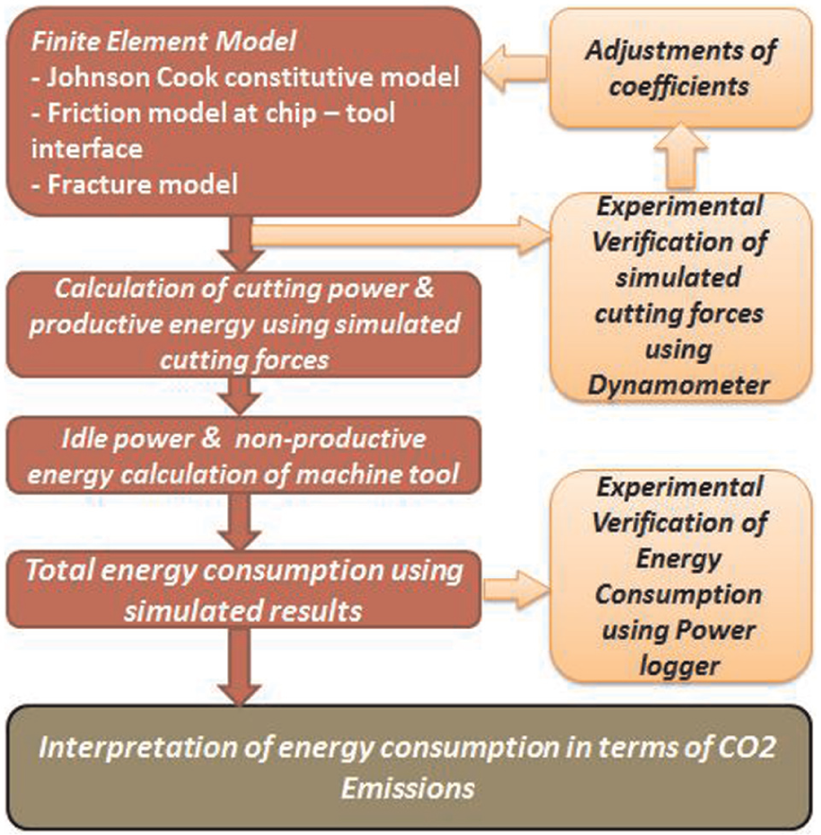
Schematic flow diagram of proposed methodology.
Experimental setup
Workpiece material
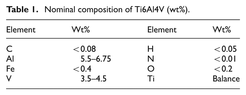
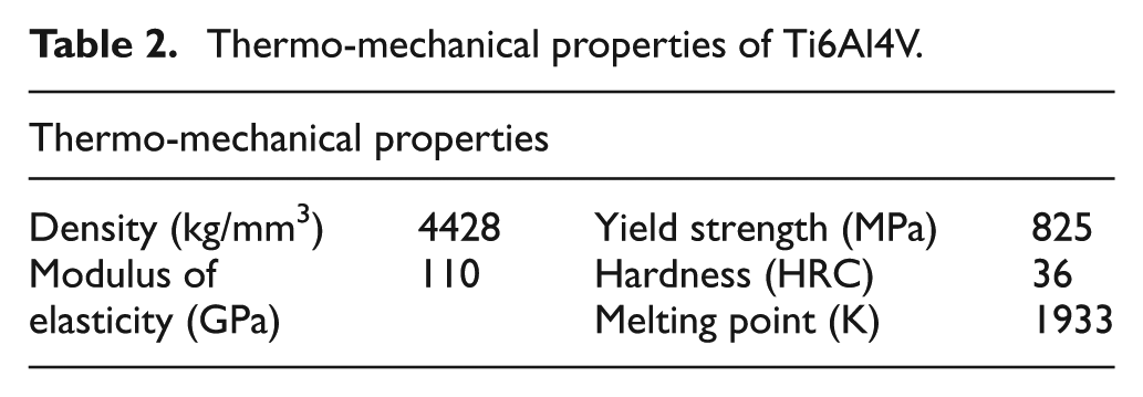
The presented machining study was performed on α–β titanium alloy (Ti6Al4V) that was available in the shape of cylindrical rod under the standard of ASTM-B381. The nominal composition of Ti6Al4V is presented in Table 1. Table 2 presents the mechanical properties of the workpiece material.
Nominal composition of Ti6Al4V (wt%).
Thermo-mechanical properties of Ti6Al4V.
Cutting tool material
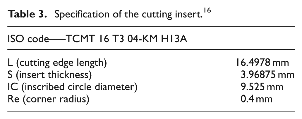
Uncoated carbide inserts from Sandvik were utilized during the experimentation. The cutting insert was available in two cutting edges. Each cutting edge was used for each experimental run. Table 3 and Figure 2 show the geometry and specifications of the cutting insert.
Specification of the cutting insert. 16
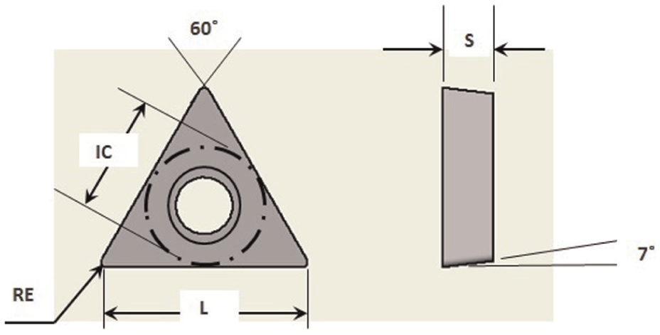
Geometry of the cutting insert. 16
Machining tests and processing parameters
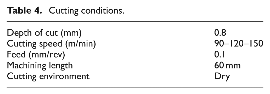
The cutting experimentation was executed on a computer numerical control (CNC) turning center. In order to verify the simulated cutting forces, Kistler multi-component dynamometer was used to measure the actual cutting forces. Power logger (PS 3500) was also utilized to capture the actual power and energy consumed during the cutting experiments. Total energy consumption from the proposed methodology was also compared and verified with actual energy consumption by capturing power and energy using data power logger (PS 3500). Figure 3 shows the schematic illustration of experimental setup. Table 4 represents the cutting parameters used for this study.
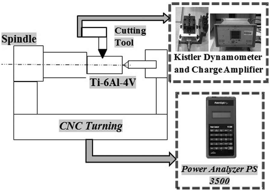
Schematic diagram of experimental setup.
Cutting conditions.
Finite element modeling
In order to develop finite element–based simulations of the machining operation, DEFORM-3D finite element software was utilized. The finite element model utilized modified Johnson–Cook constitutive equation to develop flow stress data for titanium alloy (Ti6Al4V) as a workpiece material. The finite element model also used the reference data of uncoated carbide tool available in the DEFORM library. 17
Figure 4 shows the three-dimensional (3D) finite element model with mesh orientations of cutting tool and workpiece. The workpiece was modeled as a plastic object, using 65,174 meshing elements. However, the tool was modeled as a rigid object with 18,000 meshing elements. Meshed workpiece was fixed in x-, y- and z-directions. However, meshed tool moved in +y-axis.
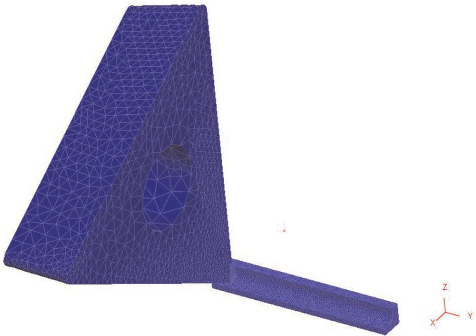
The 3D model and mesh orientations.
Material constitutive model
The modified Johnson–Cook constitutive model was employed in the finite element model to predict and incorporate the behavior of flow stresses for titanium alloy (Ti6Al4V). 18 The modified Johnson–Cook model is denoted in equation (1). The flow softening effect at higher strains is depicted by using tanh function, where parameters p, r, S and D are material dependent in nature 19
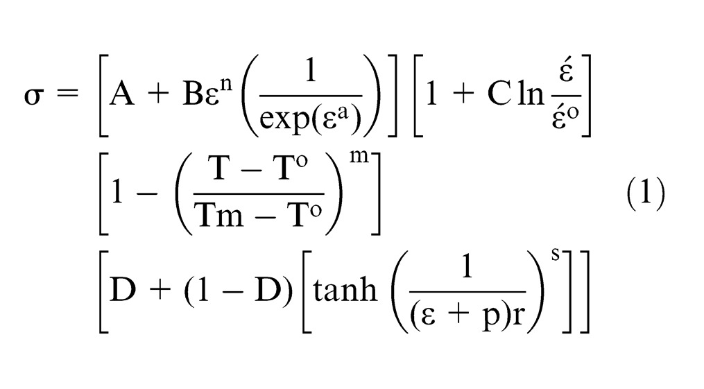
In equation (1),
where σ denotes the flow stress, ε is the true plastic strain,
Johnson–Cook parameters. 13

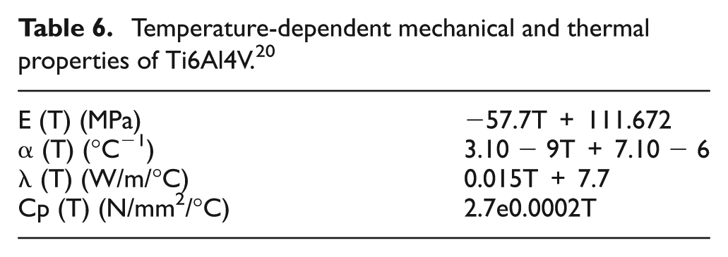
Temperature-dependent mechanical and thermal properties of Ti6Al4V. 20
Tool–chip friction model
In this study, a friction model was implemented at the tool–chip interface to simulate the finite element–based model accurately. The study incorporated shear friction law in the DEFORM-3D finite element package to describe the friction behavior at tool–chip interface. Shear friction law is generally used in machining simulations to represent severe contact and is shown in equation (2) 21

In equation (2), m° denotes the frictional factor, τ is the shear stress in friction and k is the shear flow stress of the work material. The study used friction factor (m°) value as 0.6 for uncoated carbide tools.
Fracture model
The Cockroft and Latham 22 fracture criterion was employed in 3D finite element simulations to enable the fracture mechanism. DEFORM software package has the ability to incorporate fracture mechanism in the material constitutive model. According to Cockroft and Latham model, damage initiates once integral of maximum principal stress component over a strain path becomes equivalent to the certain critical damage value. Equation (3) denotes the Cockroft and Latham damage model. This study utilized the commonly used critical damage value as 0.6

where εf is the effective strain, σ1 is the maximum principal stress and D is the critical damage value in reference with workpiece material (Figure 5).
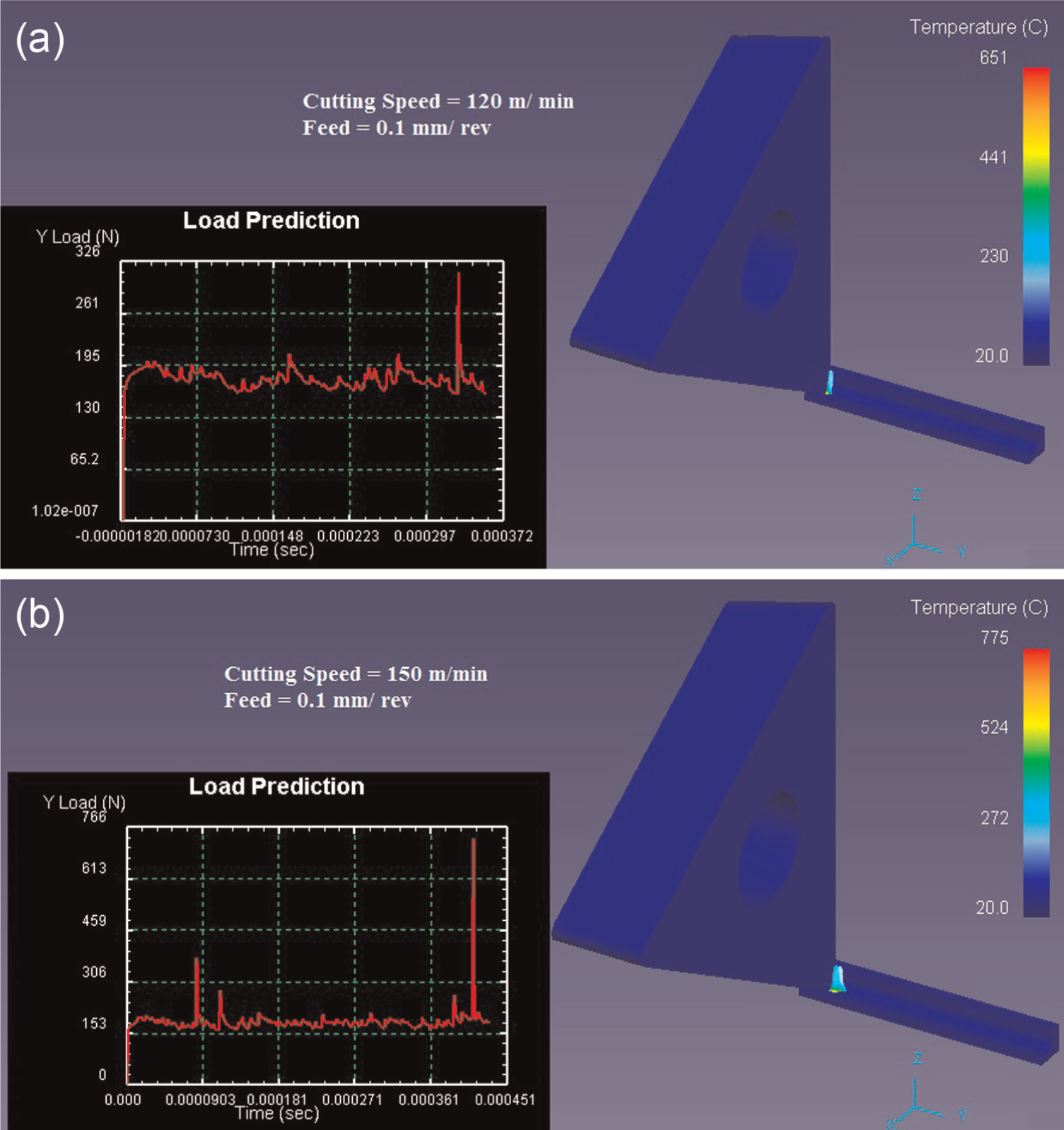
Finite element simulated cutting forces and temperature fields for feed rate of 0.1 mm/rev: (a) cutting speed (Vc) of 120 m/min and (b) cutting speed (Vc) of 150 m/min.
Cutting force analysis
The experimental cutting forces are reported and compared with the simulated cutting forces as shown in Figure 6. In Figure 6, no substantial increase in the magnitude of the cutting force was recorded with increasing cutting speed. However, a slight decrease in the cutting force was observed in the cutting forces. Increase in the cutting speed results in the generation of high temperature in the cutting zone. Thermal softening phenomenon can be attributed as a reason of stable cutting forces at higher levels of cutting speeds.
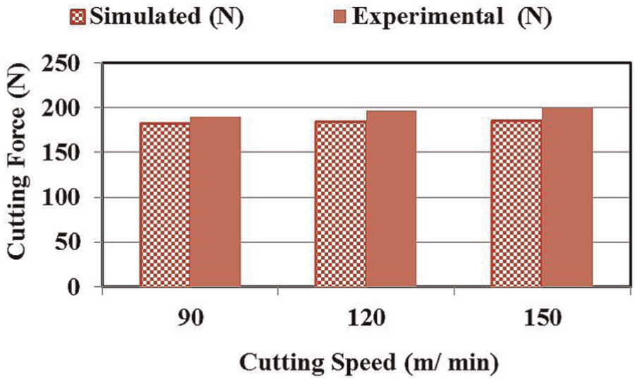
Comparison of experimental and simulated cutting forces.
The experimental and simulated cutting forces were found in good agreement with each other. The finite element simulations predicted cutting forces with an error in the range of 3.4%−7.0%.
Energy consumption analysis
As illustrated previously by several researchers,4–11,23 the total energy consumption of a machining process can be mainly divided into the energy consumed in the core cutting phase and idle energy consumed in running the machine modules at zero load. Equation (4) shows the total energy consumption of a machining operation as discussed above

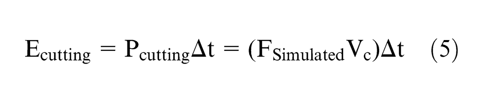
As available in the literature, 24 the cutting force (Fc) in the orthogonal machining model has the same direction as of the cutting speed (Vc) and can be used to calculate power involved in the cutting action. Energy involved in the cutting action can be calculated by taking the product of time involved in the cutting action. Equation (5) shows the energy consumed in the cutting process
In order to estimate the idle energy (E idle) involved in the machining process at certain cutting conditions, power has been captured for air cutting (dry run) using a power logger PS 3500. The total energy consumed in the machining was predicted by combining the energy in cutting using simulated cutting forces and energy consumed by machine tool during air cutting (dry run). Figure 7 shows the comparison of energy consumption using the proposed method and experimental measurements. The proposed methodology was also validated experimentally by capturing the power and energy consumption in the actual machining at specified levels of cutting conditions. The time interval (Δt) was selected very carefully for each cutting speed after analyzing the cutting duration with the help of power signal using power logger.
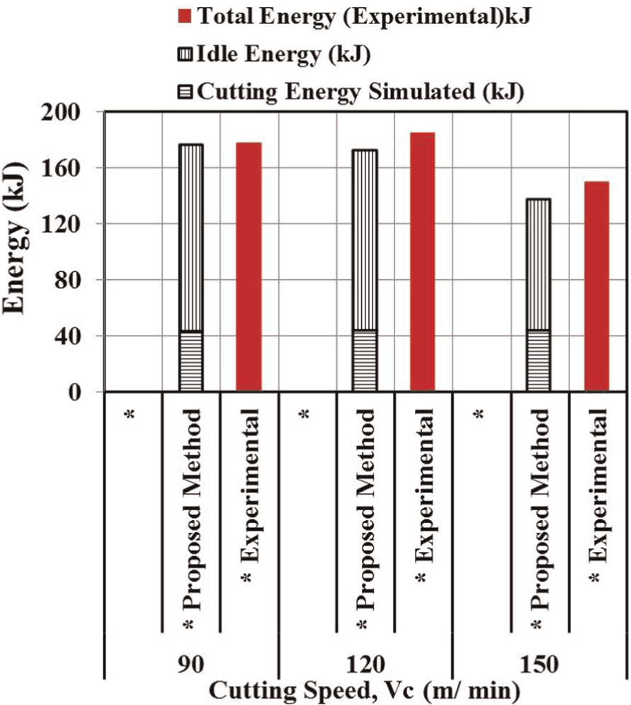
Comparison of energy consumption between experimental and proposed methods.
For this study, machining length (60 mm) and cutting speeds (90, 120 and 150 m/min) were kept constant due to which variation in machine speed was obtained by workpiece diameter. Variation in the diameter resulted in different machining times for different cutting speeds. The experimental work and the proposed method to estimate energy consumption were found in good agreement with each other. The proposed method predicted energy consumption of machine tool with an error in the range of 1%−8%.
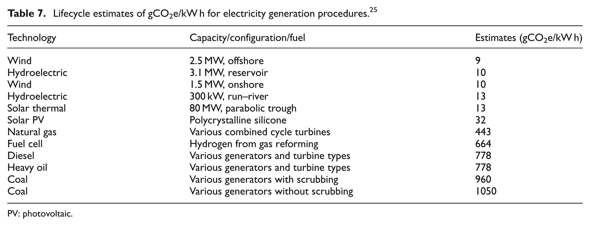
Table 7 consists of the data related to the CO2 emissions (e/kW h) produced in the life cycle of electricity generation using different types of energy sources. As in United Arab Emirates, most of the electricity is generated from fossil fuels, so this study has used the value of 778 gCO2e/kW h in order to estimate CO2 emissions from computed energy consumption. The calculated values of CO2 emissions (e/kW h) were found to be 38.00, 37.02 and 29.65 (gCO2e/kW h) for the cutting speeds of 90, 120 and 150 m/min, respectively.
Lifecycle estimates of gCO2e/kW h for electricity generation procedures. 25
PV: photovoltaic.
Conclusion
The conclusions drawn from this study are as follows:
The proposed method incorporated finite element machining simulations to predict the energy consumed during the cutting action. Energy consumed in the dry run was measured experimentally to compute the idle energy used by the machine tool. The presented approach was found in good agreement with the experimental findings. The prediction error between the experiments and the presented approach was found in the range of 1%−8%.
The proposed method was found efficient in calculating the equivalent CO2 emissions involved in the machining operation.
In the proposed method, there was no actual machining involved in the computation of the total energy consumed in the machining process. It provides an easier and cheaper solution for energy computation when machining difficult-to-cut materials.
Future recommendations
This study has provided details of an initial development of a finite element model for predicting energy in case of turning operation under dry cutting environment. The proposed method can be further extended for other processes like drilling and milling operations for both dry and flood cutting environments. However, finite element simulation of milling and drilling processes is more demanding because of high complexity involved. The approach can also be used to develop a CO2 emission–based calculator for assessment of environmental impact. In order to develop a CO2 emission calculator for environmental impact, idle energy consumption data of a machine tool should be available at different material removal rates. However, cutting energy can be predicted virtually using finite element simulations. The total energy consumption of a process can be converted into equivalent CO2 emissions based on the selection of geographical location.
Footnotes
Appendix 1
Declaration of conflicting interests
The authors declare that there is no conflict of interest.
Funding
This study received the financial support of the National Research Foundation.