
Abstract
In this article, electromagnetic bulging of high-strength, low-conductivity Ti-6Al-4V using a T3 copper driver plate at room temperature was described. The investigation was conducted employing numerical simulation method. Numerical prediction of the deformation contour and thickness distribution were closely correlated with the experimental results. The distribution of electromagnetic force on the driver plate and impact force between the driver plate and the workpiece varying with time was obtained. Besides, deformation velocity distribution and strain rate on the workpiece were determined by analyzing the deformation process. Energy efficiency of the process was determined to be 1.34%. Distribution of total electromagnetic force over time is characteristic of a sine-squared attenuation function. Velocity of the second impact near the center zone is 229.36 m/s with a corresponding impact pressure of 3.42 GPa. The results of this investigation are significant in the design of an improved process of electromagnetic forming of Ti-6Al-4V and other low-conductivity metals.
Introduction
As a means of reducing energy consumption and improving safety, motor vehicles and aircraft benefit from weight reduction. Two of the primary means of achieving weight reduction are the use of lightweight materials and lightweight structural design. The most commonly used lightweight materials are aluminum, magnesium, titanium and their alloys. However, formability of these materials at room temperature is poor compared with that of normal carbon steel. Forming methods currently in use include superplastic forming, warm forming and the use of intermediate heat treatment. Each of these processes has economic and/or efficiency disadvantages. Superplastic forming requires excessive quantities of material and process efficiency is poor. The warm forming process requires expensive high-quality lubricants. Multi-step processing requires supplemental heat treatment between steps, resulting in significant increases in production cost. 1 A new forming method that eliminates or reduces some or all these production penalties is clearly desirable.
Previous studies indicate that electromagnetic forming technology has certain advantages over other processes. These include high forming velocity, a single mold, simple forming equipment and ease with which other technologies can be incorporated. Due to the high velocity of electromagnetic forming, formability of materials at room temperature can be improved, wrinkling can be reduced and springback minimized. Electromagnetic forming is thus a very promising technology.2,3
Ti-6Al-4V is a duplex alloy with phases of α and β. At room temperature, the phase is mainly the α phase with a hexagonal close-packed (HCP) structure with fewer slip systems. As a result, Ti-6Al-4V exhibits poor formability at room temperature. High velocities that are characteristic of electromagnetic forming can be used to mitigate titanium alloy formability limitations.
A number of scholars have previously studied electromagnetic forming of titanium alloys. Takahashi et al. used an aluminum driver plate to form titanium. Without the driver, investigators determined that electromagnetic forming could achieve a maximum deflection of only 2.3 mm in titanium plate. Experiments using aluminum driver plates of different thicknesses were conducted. Distribution of magnetic field intensity resulting from the use of drivers of different radii in experiments was analyzed. The results indicated a direct relationship; an increase in the thickness of the aluminum driver plate resulted in increased load. The load was stable when the thickness of the driver plate was equal to the skin depth of the alloy subjected to forming. However, as driver thickness increased beyond that of skin depth, deformation resistance increased. Studies showed that although the deformation of materials using electromagnetic forming was inconsistent, it could significantly improve formability. 4
Revuelta et al. compared and analyzed the electromagnetic forming and deep drawing process of AZ310-O magnesium alloy and CP grade 1 titanium plate. The results indicated that electromagnetic forming, with the use of an aluminum alloy driver plate, could improve formability. 5
Srinivasan studied the formability of titanium alloy plate and stainless steel plate using a copper driver plate to evaluate forming by electromagnetic stamping. Forming efficiency improved with this technique. 6
In this article, we document experimental results of the electromagnetic bulging of titanium alloy Ti-6Al-4V using a T3 copper driver plate of 0.8 mm thickness. The process was also numerically simulated using the finite element analysis (FEA) method. The results of the numerical prediction and experimental results were compared to verify the reliability of the simulation. Energy efficiency of electromagnetic forming, distribution of magnetic force on the driver plate, distribution of the deformation velocity, strain rate on the workpiece and the impact force between the driver plate and the workpiece (which varied with time) were determined by analyzing the deformation process. These results provide a reliable basis for design of a process for electromagnetic forming of titanium alloy.
Methods
Numerical simulation
Electromagnetic forming is a nonlinear process that involves the coupling of an electromagnetic field, structural field, temperature field and air flow field. With the development of computer technology and the finite element method, numerical simulation is an economical and effective tool to analyze electromagnetic forming.
Based on the numerical simulation strategy described in the literature, 7 the electromagnetic and mechanical aspects of the process are considered to be independent problems due to the high rate current discharge. A reasonable loose coupling method was used here, as shown in Figure 1. The electromagnetic force on each node was calculated in the ANSYS/EMAG software for each time increment. These results were then imposed on the mechanical model as the boundary condition in ABAQUS/Explicit software. Deformation of the workpiece was measured until the computing time equaled the configured time.
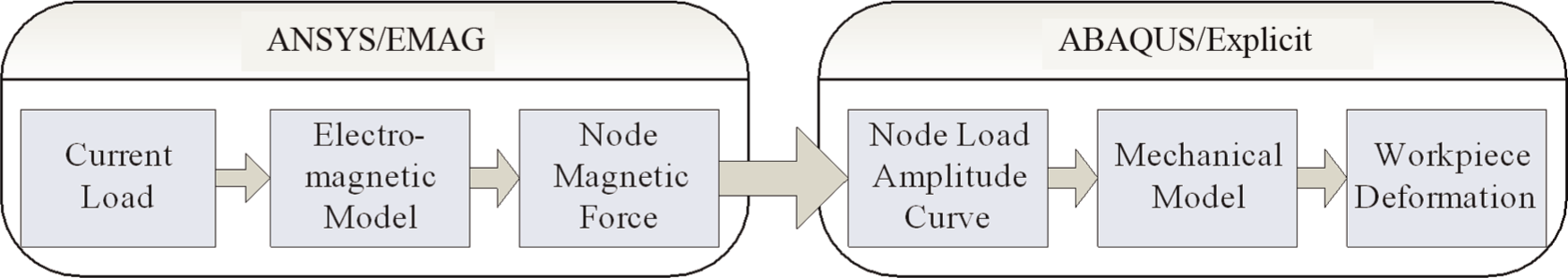
Flowchart of calculation.
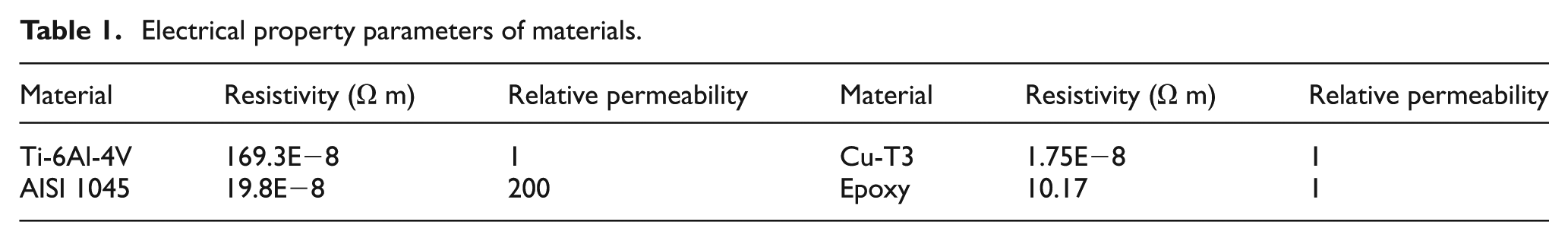
A 1/4 scale geometric model was input in the ANSYS/EMAG program with the parameters in Figure 2. A symmetric model was used, with the coil made from tightly wound copper wire with four layers, 72 turns in all. For the sake of simplicity, a circular block was modeled instead of the coil as the voltage-carrying conductive block. This was then meshed by three-dimensional (3D) magnetic solid element (Solid97), as shown in Figure 3. In the interest of the convenience and greater accuracy, a parallel boundary condition was imposed on the outside surface of the air mesh to model an unbounded 3D field rather than 3D infinite solid element (Infin111) in this study. The electrical properties of materials are listed in Table 1. Given the greater virtual skin depth induced by the high electrical resistivity of titanium alloy and the larger space between the workpiece and coil, only the driver plate was taken into consideration in the magnetic field analysis. The numerical simulation of electromagnetic forming model is shown in Figure 3(a).
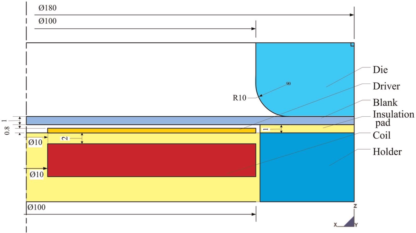
Geometric model and parameters of electromagnetic bulging.
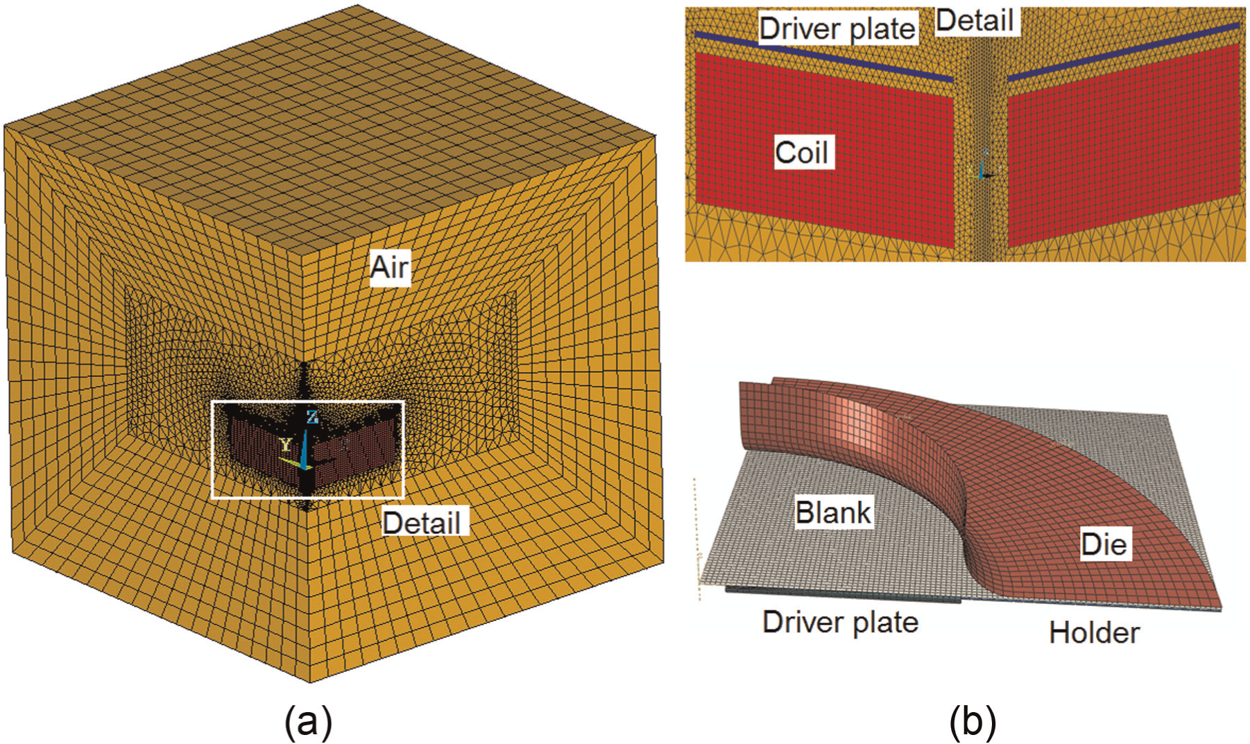
Finite element model: (a) magnetic field model and (b) structural field model.
Electrical property parameters of materials.
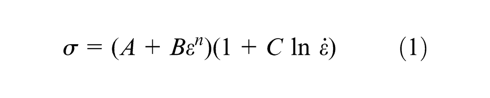
In the structural field, a four-node general-purpose shell element (S4R) and reduced integration with hourglass control were used to mesh the sheet metal. The driver plate was meshed with the eight-node linear brick element (C3D8R) and reduced integration with hourglass control, as shown in Figure 3(b). To reduce demand on the computational resource, the die was treated as a rigid body. The node electromagnetic force obtained by simulation was imparted to the workpiece. We then used the simplified Johnson–Cook model shown in equation (1) to calculate plastic deformation behavior. Wang and Xia 8 indicate that the simplified Johnson–Cook model can be effectively used to describe large deformation behavior of materials subjected to high strain rate
Experimental setup
The electromagnetic pulse generator consisted of a capacitor with 80 μf (two 160 μf capacitors connected in series), a pneumatic gap switch and a control cell, as shown in Figure 4(c). A plate spiral coil and a die with ∅100 mm open-round window and an entry radius of 10 mm were used in this study, as shown in Figure 4(a) and (b). Dimensions of the coil were ∅180 mm planar and 100 mm in height. Inner diameter of the wire portion was ∅10 mm while the outer diameter was ∅100 mm. When mounted above the potted coil, approximately 2 mm separated the driver plate from the top of the copper windings. The configuration of the titanium sheet, the driver plate and the insulation plate is shown in Figure 4(d). In order to provide a clear view of the driver plate in Figure 4(d), the titanium sheet was removed and is displayed upright beside it. The dimension of the titanium sample was 180 × 200 mm. The outer diameter of the driver plate was ∅100 mm. Thickness of the titanium sheet was 1.0 mm and the driver plate was 0.8 mm thick. The gap between the titanium sheet and the driver plate was 0.2 mm. A ∅10 mm center hole was drilled in the driver plate to provide pressure relief between the workpiece and driver plate during the forming process (Figure 5).
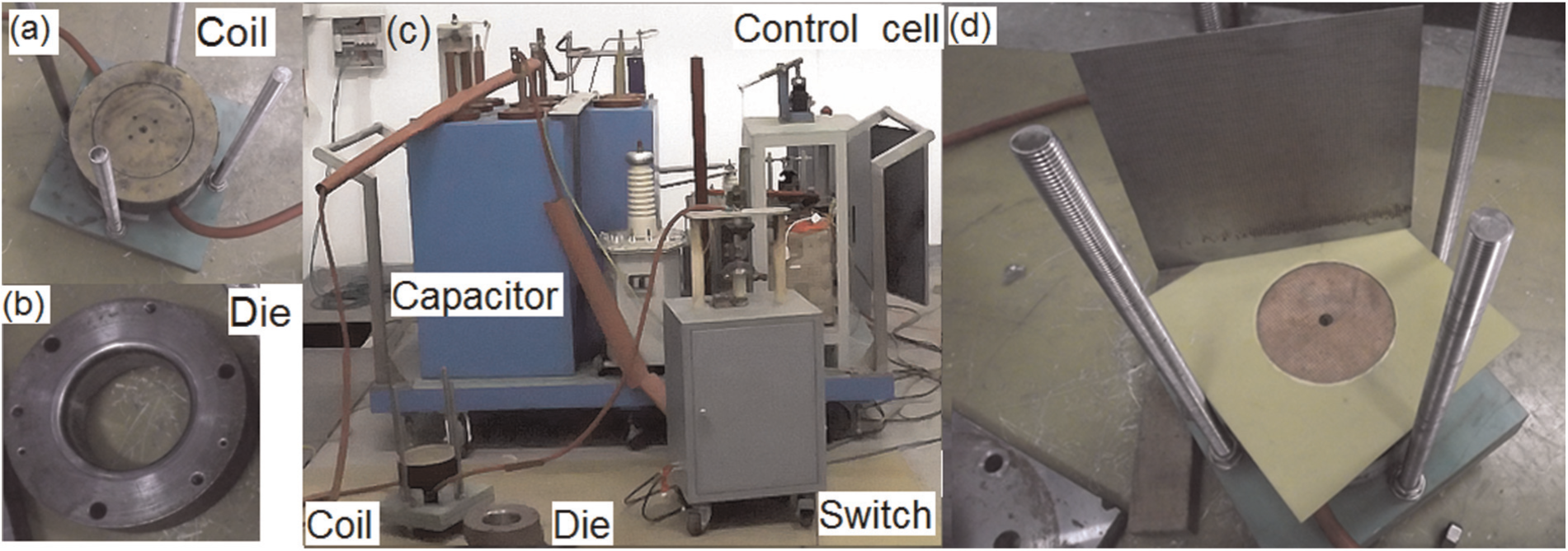
Experimental tool: (a) coil, (b) die, (c) electromagnetic forming equipment and (d) configuration of the forming.
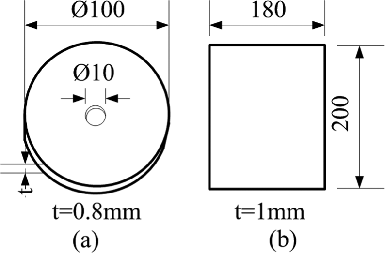
Dimensions of the sheets: (a) driver plate and (b) Ti plate.
The discharge current waveform was recorded using a Pearson current sensor and a digital oscilloscope. After the deformation of Ti-6Al-4V, the contour was characterized with the aid of ASAME Target Model (V4.1). Thickness of the sheet metal was measured using PX-7 precision ultrasonic thickness gauges.
Results
Determination of parameters
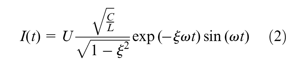
Figure 6 depicts the discharging current waveform as measured during the experiment by a Pearson current sensor and a digital oscilloscope. Mutual inductance between the coil and workpiece was ignored,7,9 so the current passing through the coil can be expressed as equation (2)
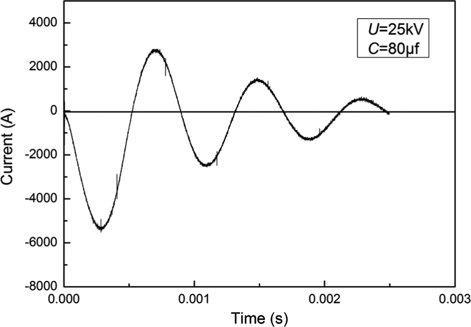
Discharging current waveform of the capacitor.
where U is the discharge voltage, C is the capacitance of capacitor, L is the inductance of forming system,
As shown in Figure 6, discharging current cycle is T = 1032.8 μs and peak current is Imax = 5360 A. The system discharging parameters used were as follows: C = 80 μf and U = 25 kV. Thus, L = 1740.36 μH, ξ = 0.1471 and ω = 6083.63 rad/s.
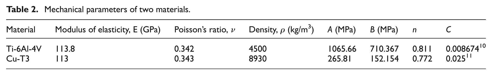
Figure 7 is the quasi-static stress versus strain curve of Ti-6Al-4V and T3 copper. Data were obtained by tensile test with a strain rate of 0.67 × 10⁻³ s−1. Material parameters A, B and n in equation (1) above were calculated by nonlinear fitting on the quasi-static stress versus strain curve. Parameter C of titanium alloy Ti-6Al-4V is equal to 0.008674 according to the literature. 10 The detail parameters of the two materials are listed below in Table 2.
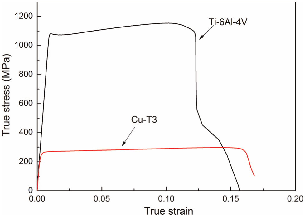
True stress versus true strain curve of Ti-6Al-4V and T3 copper.
Mechanical parameters of two materials.
Determination of deformation
The numerical prediction and experimental data of the deformed contour of the workpiece are compared in Figure 8. The numerical prediction plot curve is slightly above that of the experimental data. However, the deviation is small and the distribution trend is consistent. Figure 9 illustrates the contour of the experimental result and numerical prediction. The numerical simulation is closely correlated with the experimental result. Predicted and experimental thickness distributions of the workpiece are compared in Figure 10. “L” and “S” on the graphic represent the directions along the long side (200 mm) and short side (180 mm), respectively, as shown in Figure 9. The thickness along the long side varies slightly from that along the short side, especially near the flange. At the flange on the short side, the thickness increase is due to insufficient blank holder force (BHF) beyond R = 50 mm (Figure 10). The plotted experimental data and the curve of the numerical prediction are closely correlated.
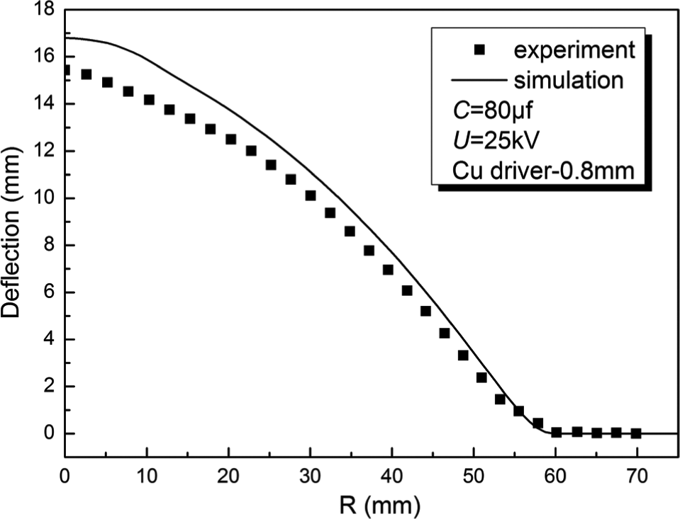
Profile of the deformed workpiece.
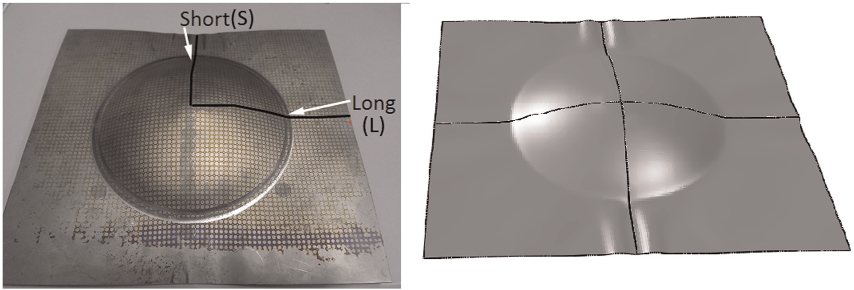
Contour of experimental results and the numerical prediction.
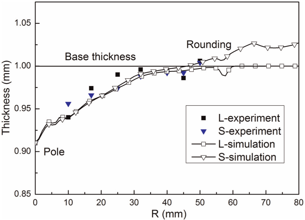
Distribution of thickness of the deformed workpiece at different locations.
Distribution of energy
In order to analyze energy efficiency, distribution of energy was plotted directly from the postprocessor of the ABAQUS software. Figure 11 is a plot of the forms of energy as a function of time.
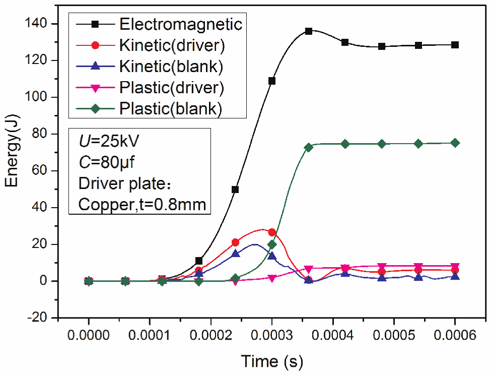
Energy as a function of time.
Electromagnetic energy transferred by the driver plate is in the form of plastic dissipated energy expended in the deformation and the kinetic energy of the blank and driver plate. The energy curves shown in Figure 11 are calculated by numerical simulation based on the 1/4 scale simulation model. Extrapolating to a full-scale model, total energy used in the deformation and movement of the workpiece and driver plate is 544.8 J. Plastic dissipation resulting from deformation of the blank (Eused ) is only 336.1 J. The energy discharged by the capacitor is calculated as

then, Edis = 25 kJ.
Energy efficiency is calculated as

then, η = 1.34%.
Distribution of the electromagnetic force
The predicted electromagnetic force on the driver plate at different points in time is shown in Figure 12. The electromagnetic force applied on the lower surface (side near the coil) was greater than that on the upper surface. Maximum electromagnetic force on the upper surface occurred in the zone near the half radius, while the force on the lower surface was greatest in the zone near R = 40 mm. Electromagnetic force varied with time due to the source current.
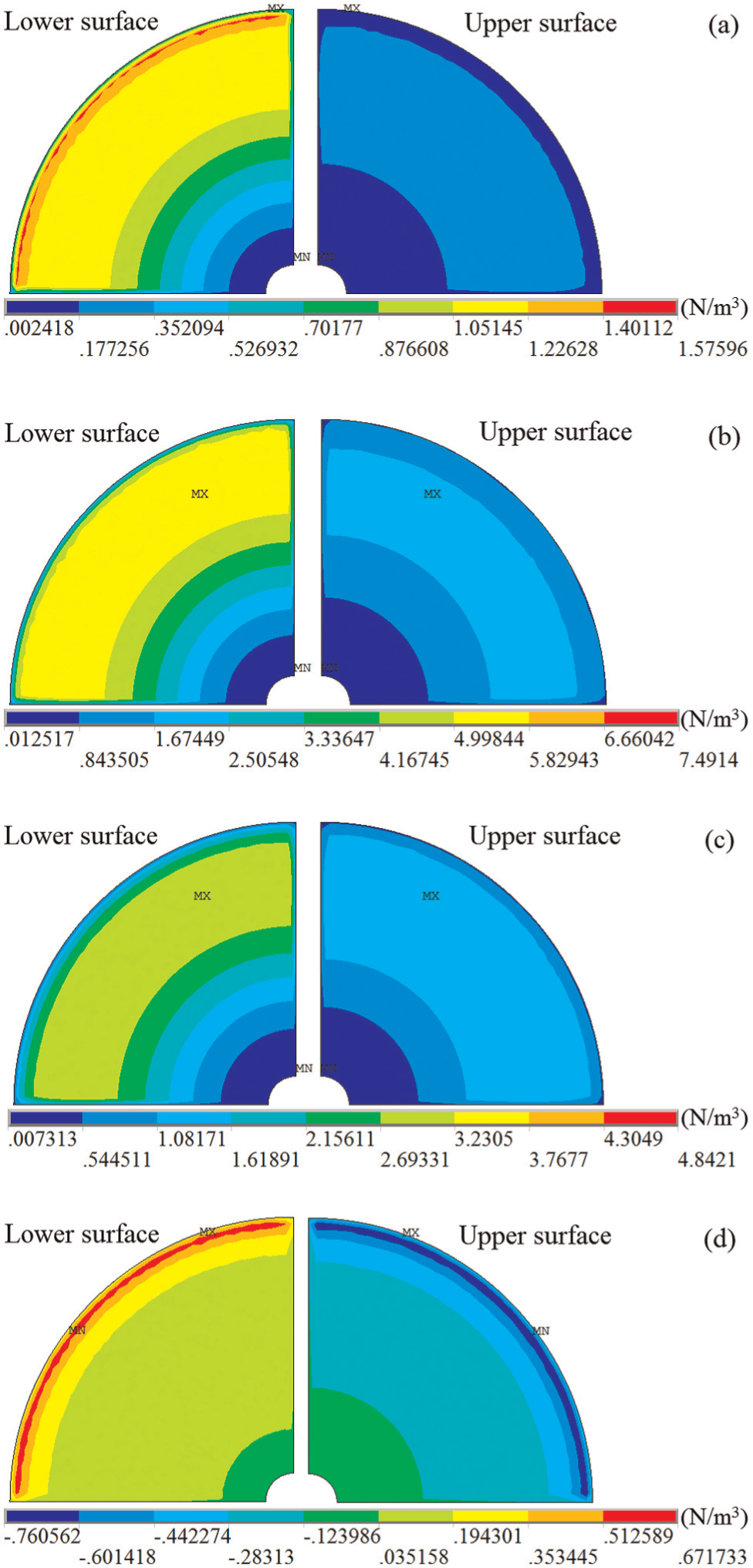
Predicted electromagnetic force distribution applied to the driver plate at different times: (a) 103 μs, (b) 258 μs, (c) 361 μs and (d) 516 μs.
Impact force
When a copper driver plate is used to facilitate electromagnetic forming of Ti-6Al-4V, the primary mechanism of deformation of the Ti-6Al-4V sheet is the impact force between the Ti-6Al-4V and the driver plate. The impact force, defined as the total force applied to the contact surface, was predicted by numerical simulation (Figure 13). At 105 μs after discharge, the impact force began to oscillate and then increased over time until the force peaked at 345 μs.
Impact force as a function of time.
Discussion
Verification of numerical simulation
The accuracy and reliability of the simulation method were validated by comparing the deformed contours of the experimental and simulated workpieces. Influence on the magnetic field distribution due to deformation of the workpiece was ignored, resulting in the slight differences observed in the simulated and experimental outcomes. Due to the high resistance of titanium sheet, the increment of electromagnetic force resulting from ignoring the deformation of workpiece was greater than the unconsidering electromagnetic force applied on the titanium sheet directly. The simulated electromagnetic force was thus slightly greater, resulting in slightly greater deformation of the calculated article. The plot of the numerical simulation lies above that of the experimental one, graphically illustrating the difference. However, the numerically simulated and experimental shape of the workpiece after deformation is closely correlated. By analyzing the thickness distribution in the workpiece, the fracture zone could be accurately predicted. Trend characteristics of the numerical prediction and experimental data were also similar. Given that the influence on the distribution of the magnetic field caused by deformation was ignored, thinning of the workpiece was more severe in the simulation than was experienced experimentally (Figure 10).
Energy efficiency
Calculated values indicate that the energy efficiency of sheet metal electromagnetic forming with a driver plate is relatively low, due in part to the resistivity of titanium alloy

Here,
The coil used in this study was 72 turns, resulting in high inductance and low angular frequency as noted earlier. The skin depth of titanium alloy subjected to electromagnetic influence was thus calculated as
Electromagnetic force analysis
According to the literature, 12 the analytic equation of electromagnetic force at the different radii of the flat coil is
where I is the discharging current, N denotes turns of coil, g is the distance between the coil and workpiece,
In FEA, the total electromagnetic force is the sum of electromagnetic force on each node of the driver plate, then
where ri is the radius of nodes and m is the total number of nodes.
Assuming
Assuming
Figure 14 graphically depicts the total electromagnetic force applied to the driver plate, calculated by different methods as a function of time. The maximum total electromagnetic force calculated by simulation was Pmax
= 18.51 kN. The coefficient P
1 = 26.5 kN in equation (9) above could be obtained by nonlinear fitting of the results of numerical simulation. Equation (9) and Figure 14 show that the distribution of electromagnetic force is a sine-squared attenuation function of time. Its cycle is half that of the discharge current (
Total electromagnetic force as a function of time.
Velocity versus impact force
The calculated deformation velocity at different radii on the driver plate and workpiece, as well as the impact force between the driver plate and workpiece as a function of time, is shown in Figure 15 (numerical simulation). In Figure 15, the maximum deformation velocity imparted to the workpiece was 229.36 m/s. The deformation velocity at the center of the workpiece (R = 0 mm) increased gradually to 143.33 m/s and then decreased precipitously before increasing sharply to the maximum. This behavior is explained as follows: deformation of the workpiece was caused by the movement of the driver plate at initial contact with the workpiece (R = 25 mm) at 105 μs after discharge, as shown in Figure 16. The driver plate remained in contact with the workpiece at the R = 25 mm zone due to the distribution of electromagnetic force, as described earlier in the electromagnetic force section. Velocities at the driver and workpiece measured at the R = 25 mm zone provide conclusive evidence that the two remained in contact. When the velocity reached its first peak at 275 μs after discharge, the impact force rapidly reached maximum value. Next, the center of the driver plate deformed and made contact with the workpiece near the R = 0 mm zone at 345 μs. The velocity reached its second peak value (229.36 m/s) and deformation of the workpiece (especially near the center) continued. Thereafter, the driver plate completely separated from the workpiece. The deformation velocity applied to the workpiece at the R = 25 mm zone increased gradually and then decreased. Maximum deformation velocity was 88.13 m/s.
Impact force and deformation velocity at different radii on the workpiece as a function of time.
Contact states between the driver plate and workpiece at different times.
The impact pressure P developed when two semi-infinite elastic bodies collide at an impact velocity of Ui is 3
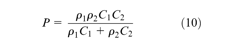
where
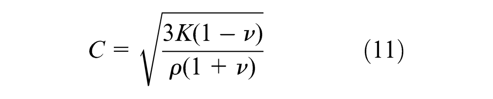
where K is the bulk modulus;
As noted in Meyers, 11 shock parameters of copper and Ti-6Al-4V for Rankine–Hugoniot state equation (12) can be obtained and listed in Table 3, then the pressure at impact between the copper driver plate and the Ti-6Al-4V workpiece near the center zone at 345 μs after discharge can be calculated

Shock wave parameters of copper and Ti-6Al-4V for Rankine–Hugoniot state equation.
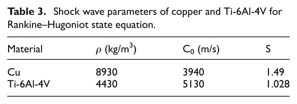
where Ui is the impact velocity and Up is the particle velocity.
The pressure versus particle velocity curve of the two materials used is shown in Figure 13. The impact velocity of the second impact at the center zone is 229.36 m/s, as shown in Figure 15. This is also the maximum deformation velocity at the workpiece. The impact pressure may be obtained directly by use of the impedance matching technique. As indicated in Figure 17, the pressure near the center zone is P = 3.42 GPa.
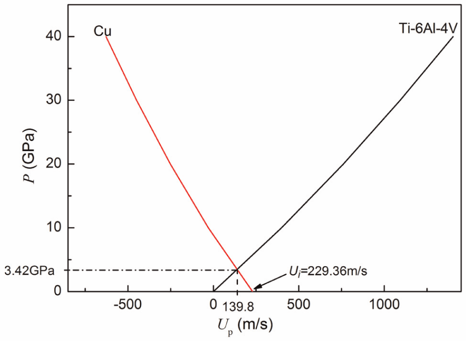
Copper driver plate impact with Ti-6Al-4V sheet at a velocity of
Impact force versus strain
Figure 18 depicts the effective strain at different radii and impact force as a function of time. The effective strain is defined as the average of effective strains on the top and bottom surfaces of the shell element. Although elastic deformation commenced when the driver plate contacted the workpiece at 105 μs after discharge, data in Figure 18 indicate that plastic deformation of the workpiece occurred when the impact force reached its maximum. Plastic deformation thus lagged behind the transmission of the impact force. Deformation occurred in a very short time and was complete before the impact force began to decrease.
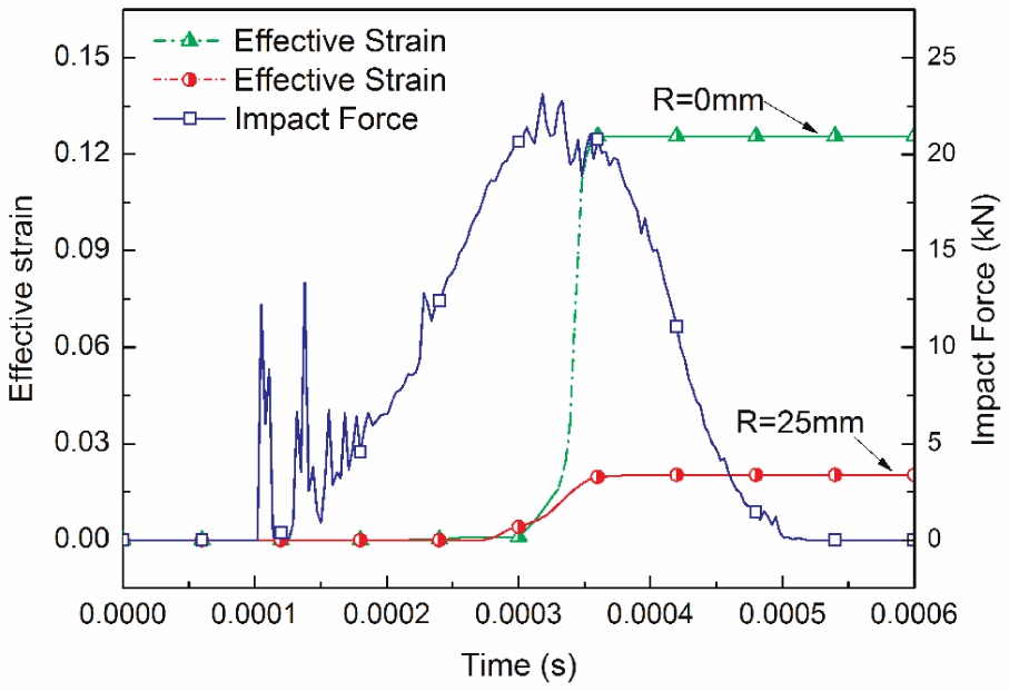
Change in effective strain and impact force over time at different radii.
Impact force versus strain rate
Figure 19 depicts strain rate at different radii on the workpiece and impact force as a function of time. As the figure illustrates, when the impact load reached its maximum, the strain rate at the center position of the workpiece simultaneously reached maximum value. Besides, it fluctuated relatively serious in the low strain rate range. However, strain rate at a point on the workpiece corresponding to 1/2 the radius of the coil was uniform throughout the forming process, with very little fluctuation. Maximum strain rate at the center of the workpiece was 4038.02 s−1. Strain rate was 1021.66 s−1 when the workpiece was contacted by the driver plate and deformation began.
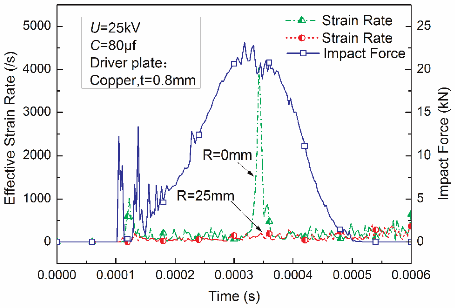
Effective strain rate at different radii on the workpiece and impact force as a function of time.
Conclusion
Numerical simulation and experimental methods of electromagnetic forming of Ti-6Al-4V driven by a copper plate of 0.8 mm thickness were conducted at room temperature. The numerical simulation data were then compared with the experimental data. The conclusions are drawn as follows:
Numerical prediction of the deformation and thickness distribution is closely correlated with the experimental results. Numerical simulation was proven to be accurate and reliable. The relationship between impact force and strain or strain rate on the workpiece as well as driver plate can be determined using the simulation method.
Energy efficiency of electromagnetic forming with a driver plate is lower than when forming a highly conductive metal without a driver plate and tube electromagnetic forming. The energy efficiency of electromagnetic forming of Ti-6Al-4V with a copper driver plate was determined to be 1.34%.
During the electromagnetic forming process, total electromagnetic force as a function of time is characteristic of a sine-squared attenuation with a cycle equal to 1/2 of the discharging current cycle.
Using the parameters described in this article, the maximum velocity of the second impact is 229.36 m/s. The corresponding impact pressure is 3.42 GPa.
Deformation of Ti-6Al-4V sheet results from the lag in transmission of the impact force caused by the collision of the copper driver plate with the titanium alloy sheet. A maximum strain rate of 4038.02 s−1 was measured at the center of the titanium alloy sheet.
Footnotes
Declaration of Conflicting Interests
The author(s) declared no potential conflicts of interest with respect to the research, authorship, and/or publication of this article.
Funding
The author(s) disclosed receipt of the following financial support for the research, authorship, and/or publication of this article: This work was supported by the National Natural Science Foundation of China (grant no. 51175201) and the National Program on Key Basic Research Project of China (grant no. 2011CB012802).