
Abstract
A study of the single-pulsed laser ablation process for a polycrystalline diamond is presented. A simulation of the laser ablation process using a finite element model is carried out to understand the temperature evolution, material removal process and mechanisms, as well as the other physical phenomena associated with this process, that is, carbon phase transformation, liquid-phase ejection and vapour/plasma shielding effect. It is found that mass material removal can be achieved through surface evaporation under a higher laser pulse energy. It is further found that diamond graphitization under laser irradiation is responsible for heat losses due to the large heat accumulation in the graphitized diamond, while cobalt melting suppresses the evaporation of cobalt phase because of the heat consumption for solid–liquid transition. Crater depth and surface formation are also investigated experimentally on the polycrystalline diamond using single-pulsed laser ablation. The predicted crater depths are in reasonably good agreement with the corresponding experimental results.
Introduction
With highly attractive properties, such as extremely high hardness, high fracture toughness and high degree of chemical inertness, polycrystalline diamond (PCD) is being widely used as tool materials for machining difficult-to-machine materials such as glasses and ceramics as well as for drill bits in oil and gas exploration. 1 However, the high hardness and brittleness of the PCD materials make them difficult to machine with low machining efficiency using the conventional grinding process. Machining technologies using the electrical discharge machining (EDM) principle including wired EDM, wire electro-discharge grinding (WEDG), electrical discharge milling and ultrasonic EDM are regarded as the most desirable methods for shaping PCD because of their capability to create complex shapes and less dependent on the mechanical properties of the workpiece material.2,3 However, these EDM-related technologies are limited to processing electrically conductive materials and are associated with tool wear and slow material removal rate (MRR). Furthermore, they often cause diamond grain detachments, residual stresses and damages on the machined PCD surfaces. 4
In recent years, studies have been undertaken to use the laser machining technology for the high efficient processing of brittle and hard materials such as PCD. This includes the investigations to assess the feasibility of applying short-pulsed lasers, ultra-short-pulsed lasers and other novel laser-related machining techniques for material processing.5–7 Precision and near damage-free machining could be achieved by using lasers of ultra-short pulses, but their capability at this stage of development makes them unsuitable for high MRR. Other lasers like nanosecond-pulsed lasers are more desirable for high efficient micromachining if the process-induced damages can be properly controlled.
Some important studies on nanosecond-pulsed laser machining have been carried out to investigate the machining performance and material removal mechanisms in order to achieve a better control of the machining process.8,9 However, the ablation mechanisms cannot be adequately understood to improve the machining process through experimental studies since the physical process involved cannot be observed or measured experimentally. As such, various models have been developed to simulate the laser–material interaction and understand the material removal mechanisms.
As the nanosecond-pulsed laser machining process uses thermal energy for melting and vaporizing material, analytical models have been developed based on heat conduction equations associated with energy conservation for predicting the temperature distribution and material removal process for a particular target material. 10 However, the complicated model formulation and long computation time of the analytical approaches make it difficult in dealing with non-linear problems and complex boundary conditions.
By contrast, numerical techniques for solving thermal equations can easily include the variation in material parameters in the calculations. Furthermore, such calculations can be performed for almost any geometry of target material and for complex boundary conditions. Numerical modelling of material processing with laser pulses of nanosecond duration has been studied extensively for a better understanding of the material removal process. These studies have been primarily focused on the processing of metal, semiconductor and ceramic targets, and focused on studying the process parameter selection, material removal and surface formation, residual stress and thermal damages aiming at process optimization.11–13 There has also been some attention given to investigating material removal mechanisms under various laser fluence regions, as well as the physical phenomena in the ablation process in terms of the ionization and expansion of vaporized plume, and energy and mass transfer between the material and the vaporized matters.14,15
Despite these studies, little is known about the laser–PCD interaction in nanosecond-pulsed laser ablation. An important aspect in the modelling of PCD machining by lasers is the capability of predicting the transient diamond–graphite transition and different ablation processes between the multiphase (diamond and cobalt binder) of the PCD target which significantly affect the absorption of laser energy and heat diffusion. Furthermore, other phenomena take place in laser ablation, such as the formation of vapour/plasma plume, and recoil pressure induced by the evaporation of materials, whose effects remain to be studied. Likewise, the specific properties of PCD under the irradiation of laser pulses require a careful examination. Nevertheless, some important studies have been reported. Windholz and Molian 16 modelled material removal process and simulated the ablation threshold in the excimer laser machining of a deposited diamond layer through chemical vapour deposition (CVD), but the other aspects such as carbon phase change and plasma shielding effect have yet to be considered. The femtosecond laser ablation process for PCD has also been investigated using molecular dynamic (MD) simulation, 17 although further studies are required to understand the various phenomena involved in the ablation process. Moreover, models for predicting the graphitization of diamond under laser irradiation have been proposed. 18 It should be noted that the above-mentioned modelling efforts focus on only one or some of the physical phenomena occurred in the laser machining of PCD, and an investigation is required to give an in-depth understanding of the laser–PCD interaction.
This study is attempted to understand the physical phenomena associated with the laser ablation of PCD through a numerical simulation and experimental investigation. A finite element (FE) model based on the heat conduction equation is developed and used to simulate the laser ablation process under different laser pulse energies. The temperature-dependent thermophysical properties and the thermal convection and radiation boundary conditions are considered in the computation. PCD ablation experiment is performed using a nanosecond-pulsed fibre laser. The ablation depths are measured and ablation mechanisms are analysed under different laser pulse energies. The computational model is verified quantitatively by comparing the predicted ablation depths by the model with the corresponding experimental data. The laser heating and the associated physical processes in the laser ablation process are then analysed using the computational model.
Computational model
Computational domain and thermal analysis
Figure 1 shows a schematic view of the model setup. A Gaussian-distributed laser beam with its spot centre at the origin of a Cartesian coordinate system is considered. This gives an axisymmetric laser energy distribution on the target material. Thus, a two-dimensional (2D) geometry along the cross section of the laser beam and containing the laser beam axis is used for the computational model, and due to its axis-symmetry, a half of the cross section is actually considered. Two major compositions, cobalt as the bonding material and diamond grain, contained in the PCD material are of particular interest in understanding the laser ablation mechanisms. The diamond grains have a large average size of 25 µm in diameter, and the cobalt content is very small (about 2%). The diamond grains and cobalt distribute randomly in the PCD from the fabrication process. It is apparent that a model to represent the actual diamond–cobalt arrangement insider the PCD will be very complicated, if not impossible. To simplify the model, a randomly chosen strip of 1.5 µm is embedded in the FE model to represent the cobalt phase, as shown in Figure 1, so that the model can facilitate the investigation of the ablation mechanisms for both the diamond and cobalt phases.
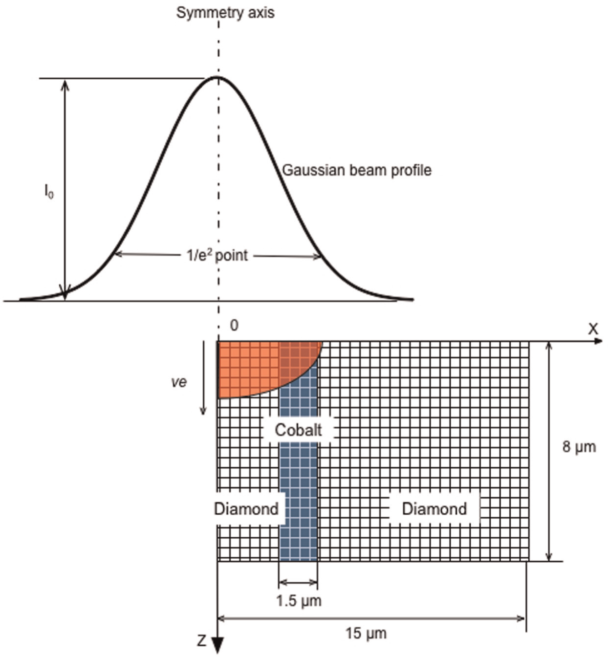
Schematic view of a laser beam profile and the ablation model at the cross section of the laser beam axis.
The PCD target is in the Z > 0 region with its surface fixed at Z = 0, while laser beam propagates in the +Z-direction. Under the laser radiation, the temperature of the target increases and surface vaporization may occur. As the target is being ablated, the target surface recedes in the +Z-direction with a vaporization or material removal velocity of ve. In this coordinate system, the heat conduction equation in the PCD can be given as 19
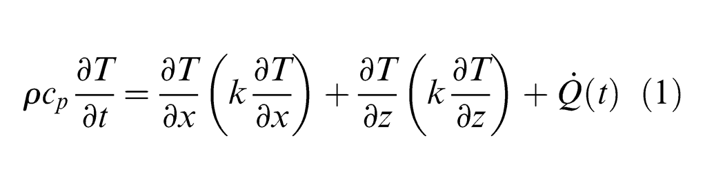
where ρ, cp and k are the mass density (kg/m3), specific heat (J/kg K) and thermal conductivity (W/m K) of the target material, respectively, and
In this study, the laser beam has a spatial profile that is rotationally symmetric about the axis of the laser beam propagating into the target. The laser energy distribution in the radial direction can be approximately formulated as the Gaussian function. Thus, in a coordinate system that is fixed with reference to the laser beam, the laser energy deposited in the PCD can be written as 20
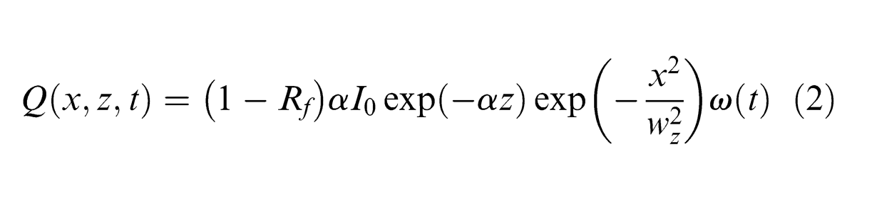
where Rf and α are the reflectivity and absorption coefficient of material, respectively, x is the radial distance from the laser beam centre, wz is the laser beam radius (µm) and ω(t) is the temporal dependence of the laser pulse (pulse shape).
In this study, the beam radius represents the full width at which the intensity drops to 1/e 2 of the maximum value, as shown in Figure 1. Using z as the distance between the focal plane and the working plane, the laser beam radius wz at any working plane can be expressed as 21
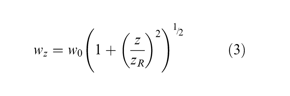
where w0 is the beam radius at the focal plane and zR is the Raleigh range.
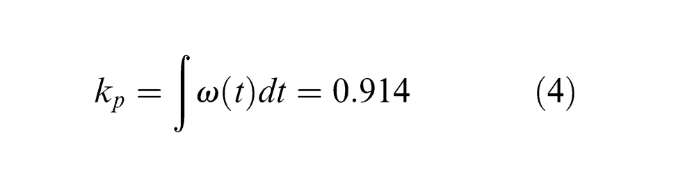
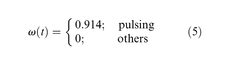
Due to the complexity and high non-linearity of the pulse shape ω(t) in the time domain (Figure 2(a)), the laser source is considered to have an equivalent uniform pulse by introducing a pulse shape coefficient kp based on the technical date of the laser used in this study, that is
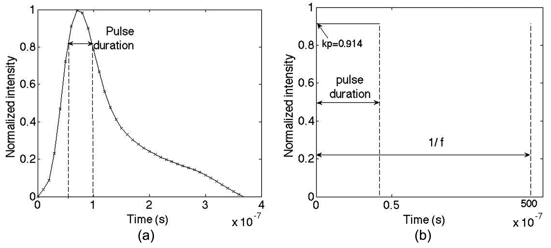
(a) Technical data of laser pulse shape in the time domain and (b) approximated uniform laser pulse shape in the time domain.
The total pulse energies under the actual and the approximated condition in equation (4) are approximately equal. The pulse duration (42 ns) is defined as the width where the intensity attenuates to ˜0.82Ipeak (Figure 2(a)). Thus, the time function of the laser intensity used in the model is given by (see Figure 2(b))
Boundary conditions
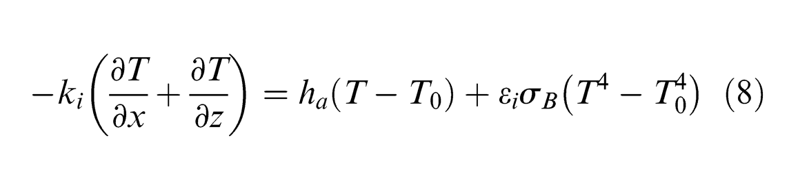
The initial temperature of Ta = 300 K is applied to all surfaces, where Ta is the ambient temperature. The top surface in Figure 1 is exposed to the laser irradiation and the corresponding convection and radiation. Thus, the heat transfer balance across this surface can be determined by 19
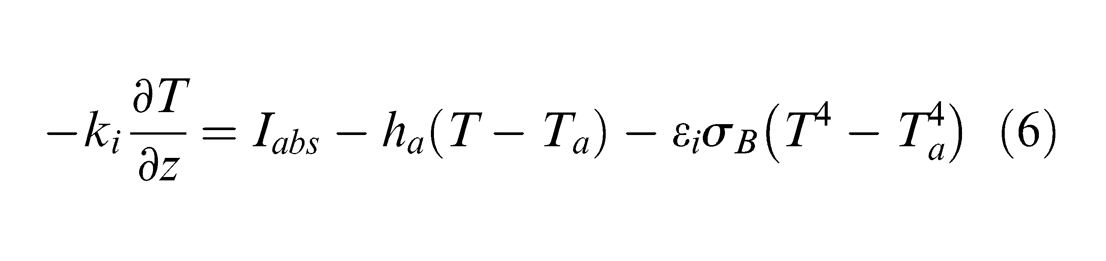
where Iabs is the laser intensity absorbed by the target surface, ha is the convective heat transfer coefficient (10 W/m2 K), 22 εi is the emissivity of material for radiation and σB is the Stefan–Boltzmann’s constant (5.67 × 10⁻⁸ W/m2 K4). 19
Since the depth of the laser-irradiated region is considerably smaller than the thickness of the PCD model, the Neumann boundary condition for the bottom surface is applied where the boundary satisfies the adiabatic condition as denoted by

For all the other surfaces (considering the axis-symmetry of the model shown in Figure 1), a cooling condition considering free convection and thermal radiation is used, 19 that is
Surface evaporation
Material ablation by infrared lasers in a nanosecond pulse duration takes place essentially by a thermal process. 23 Based on the laser intensities applied in this study (1.52–6.07 GW/m2), normal vaporization is considered as the dominant material removal process in laser ablation of PCD. Thus, the velocity of material vaporized from the target surface, ve, can be approximated by the Hertz–Knudsen equation, 24 that is
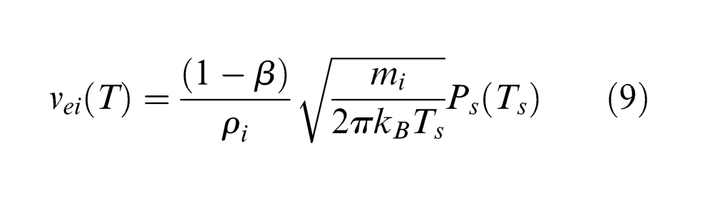
where β is the condensation coefficient and is 0.08 for stationary vaporization; 25 mi is the atomic mass of the vaporized particle, that is, carbon and cobalt atoms; ρi is the mass density for carbon or cobalt; kB is the Boltzmann constant (1.38 × 10⁻²³ J/K) and Ps(Ts) is the equilibrium vapour pressure above the target surface at a temperature Ts, which can be described by the Clausius–Clapeyron relation 26
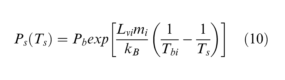
In equation (10), Pb and Tb are the reference boiling pressure (105 Pa) and equilibrium boiling temperature, respectively, and the other symbols are as defined in ‘Notation’.
Prediction of diamond graphitization
In the nanosecond-pulsed laser ablation process, PCD target is under fast laser irradiation during which the atomic transformation of diamond to graphite occurs once the individual carbon atoms overcome the potential barrier by absorbing laser photons. Meanwhile, the temperature rise in the lattice system stimulates the thermal graphitization of diamond grains. 27 As introduced by Strekalov et al., 28 a graphitization probability PG can be employed for estimating the graphitization rate of diamond in the laser field and is given by
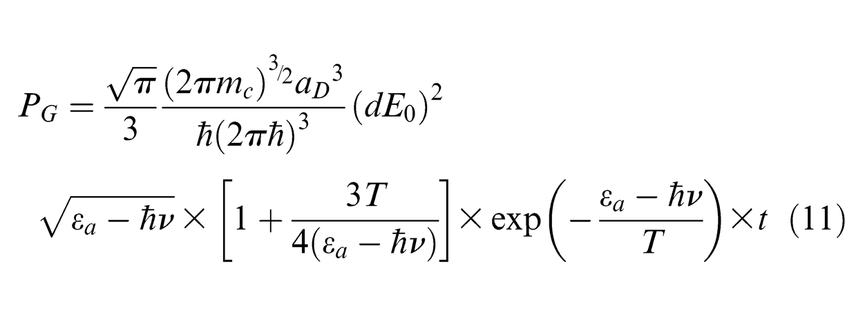
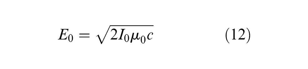
where mc is the atomic mass of carbon (2 × 10⁻²⁶ kg), aD is the lattice constant of diamond structure (1.78 × 10⁻¹⁰ m), 28 d denotes the dipole moment (7.69 × 10⁻³¹ K m) produced during the graphitization process, 29 T represents the target temperature, εα denotes the activation energy required for diamond graphitization (5.4 eV), 30 ћ is Planck constant (4.135 × 10⁻¹⁵ eV s), 31 ћν represents the photon energy absorbed by carbon atom (1.12 eV) and E0 represents the electric field induced by the electromagnetic wave produced in the laser system, which can be expressed by laser intensity I0, velocity of light c (3 × 10⁻⁸ m/s) and magnetism permeability in the vacuum µ0 (4π × 10−7 N/A2), 32 that is
Therefore, based on the target temperature and processing time, the transition probability of the carbon phase from the diamond state (sp3-bonded) to the graphite state (sp2-bonded) can be estimated using equations (11) and (12).
Cobalt melting and liquid-phase ejection
In the process of laser machining of metals, material removal takes place primarily in the liquid and vapour phases. The evolving vapour applies a recoil pressure on the surface which ejects the molten material out of the ablated area and creates a machined crater. In the nanosecond-pulsed laser machining of PCD, when temperature reaches the melting point of cobalt, it is possible that the cobalt phase is removed through melting and liquid-phase ejection by the recoil pressure. Therefore, the ejection velocity of liquid cobalt from the molten layer vl can be expressed as 33
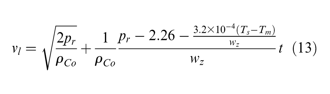
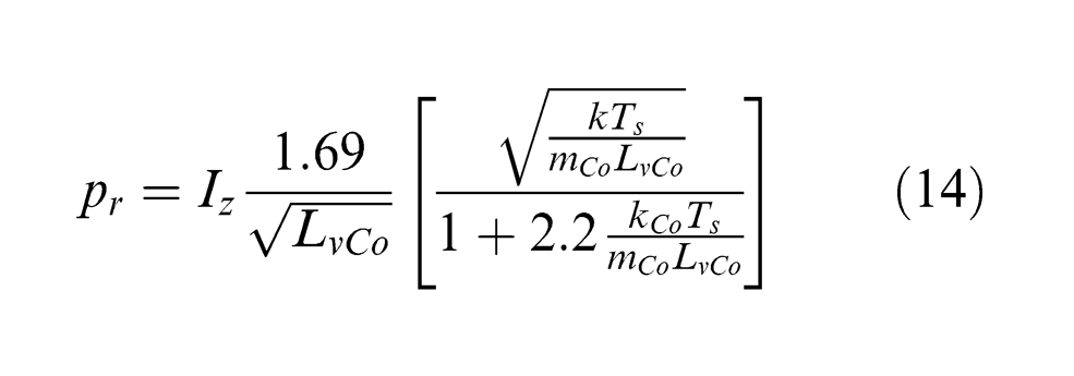
where Tm is the cobalt melting temperature and pr is the recoil pressure generated due to material evaporation upon the melted layer, which can be expressed as a function of the incident laser intensity I, as well as the cobalt thermal conductivity kCo, atomic mass mCo, latent heat of vaporization LvCo and surface temperature Ts, 34 as
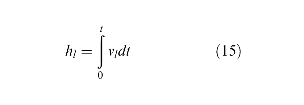
Accordingly, the machined depth of cobalt due to liquid-phase ejection hl can be estimated by
Vapour/plasma shielding effect
The ablation of solids by nanosecond laser pulses is usually associated with the formation of vapour plume when evaporation is the dominant ablation mechanism.
35
When the laser intensity is higher than 109 W/cm2, the plasma plume may form above the target surface as a result of the ionization of vaporized matters, so that plasma behaves similarly to a thick optical medium and part of the laser radiation is shielded from reaching the target surface, as illustrated in Figure 3. After the onset of material ablation, the particle density and plume temperature are affected by the rate of material evaporation and laser energy absorbed by the plume.
36
Thus, the time-dependent optical thickness of vapour/plasma plume
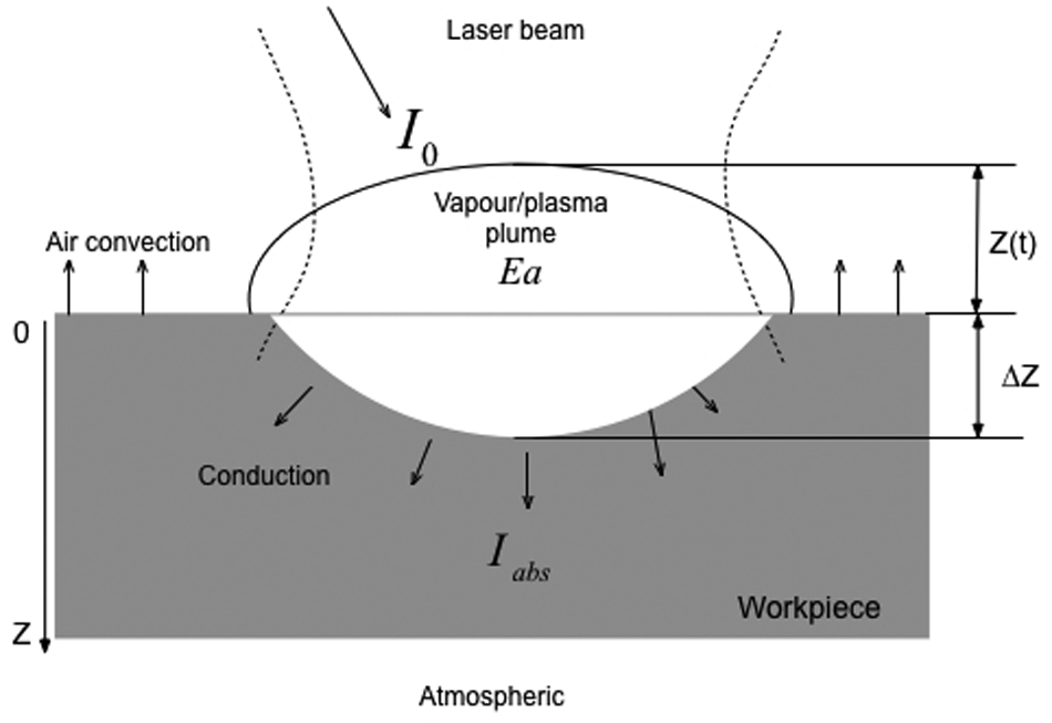
Schematic of vapour/plasma shielding effect.
where Δz is the ablation depth with time, and Ea is a self-consistent quantity and is given by38,39
The laser intensity reaching the target after passing through the plume can be calculated based on the Lambert–Beer law 19
Equations (16)–(18) for describing the dynamics of laser radiation absorption by the plasma plume are employed to estimate the attenuation of laser energy in this study.
FE analysis
The thermal and ablation models described above are solved using the FE code in ANSYS 12.1. Some trail studies were carried out first to study the effect of model dimension so that a compromise could be reached between the model accuracy and computational time (both are expected to increase with the model dimension within certain range). It has been found that when x > 14 µm in the model, the temperature developed to a near-ambient condition under all laser pulse energies and laser spot sizes considered in the study. Thus, 15 µm is used in the X-direction for the model. Likewise, to approximate the ablation depth and the isolated temperature field in the Z-direction, the depth of the FE model should be larger than the maximum ablation depth and make sure that the bottom surface temperature is in the ambient condition. It has been found that 8 µm in the Z-direction is sufficient to meet this need. As a result, the FE model shown as a half of the 2D domain in Figure 1 is defined at 15 × 8 µm in the X- and Z-axes, respectively.
A mesh independence study and a convergence test were performed. It has been found that the maximum temperature increased by only about 2% when the mesh density (model dimension/element dimension) was increased from 160 to 800, as shown in Figure 4. Considering the solution accuracy and computation time, the mesh density of 160 is used, which corresponds to the mesh size of 0.1 and 0.05 µm in the X- and Z-axes, respectively. Thus, plane elements with uniform mesh size of 0.1 x × 0.05 z µm are used in the FE model, so that the model has a total of 24,000 elements and 24,311 nodes.
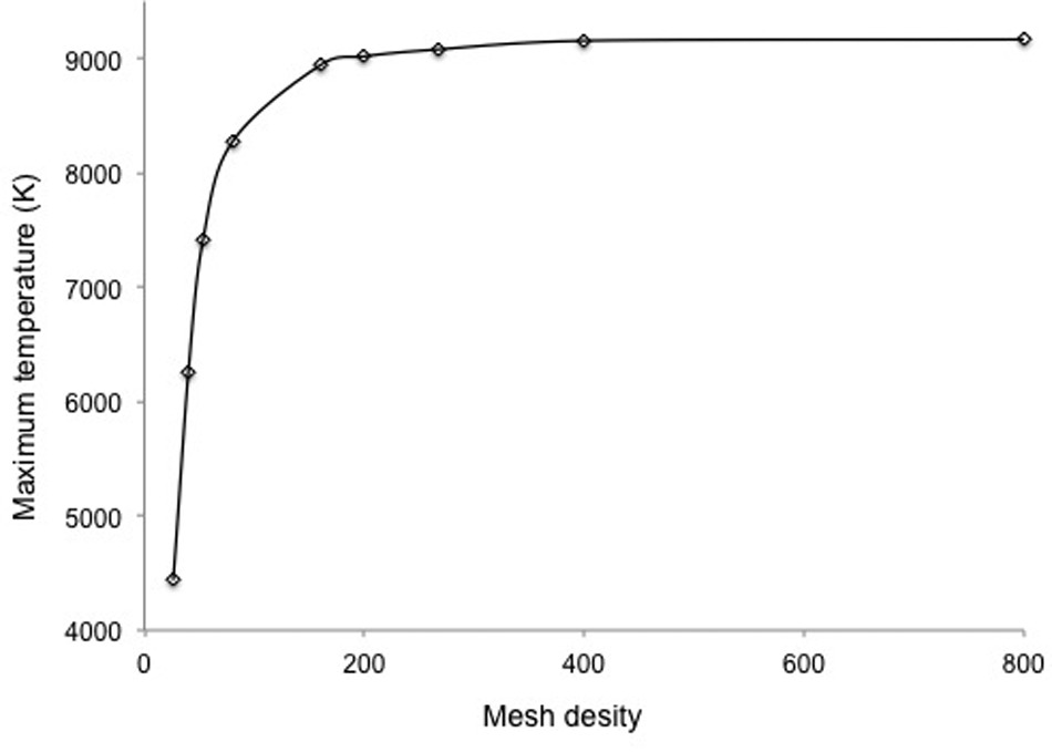
Calculated maximum surface temperature versus mesh density.
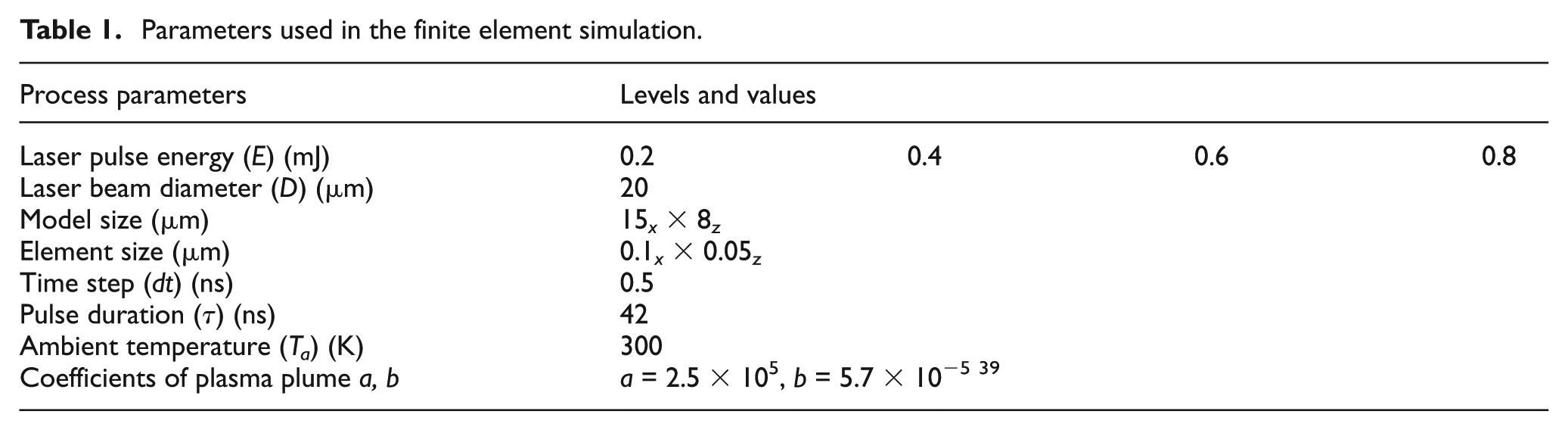
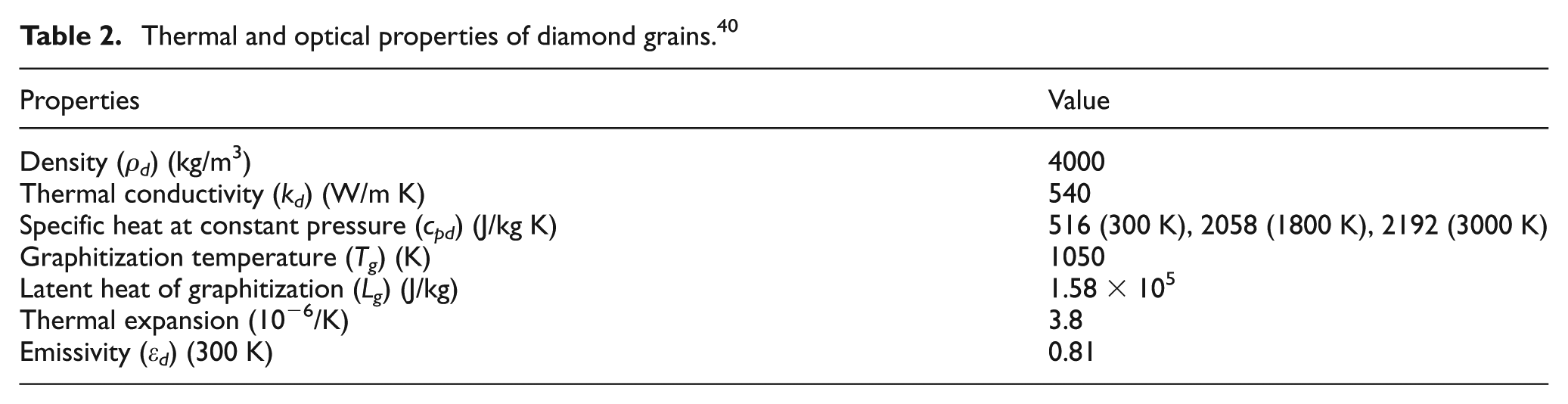
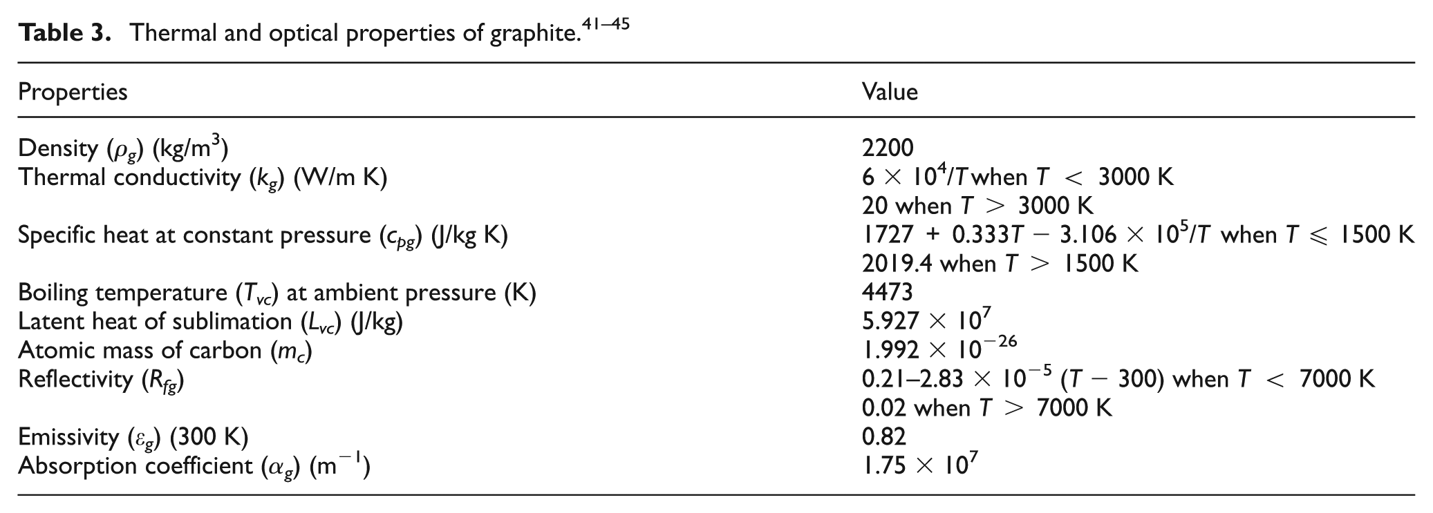
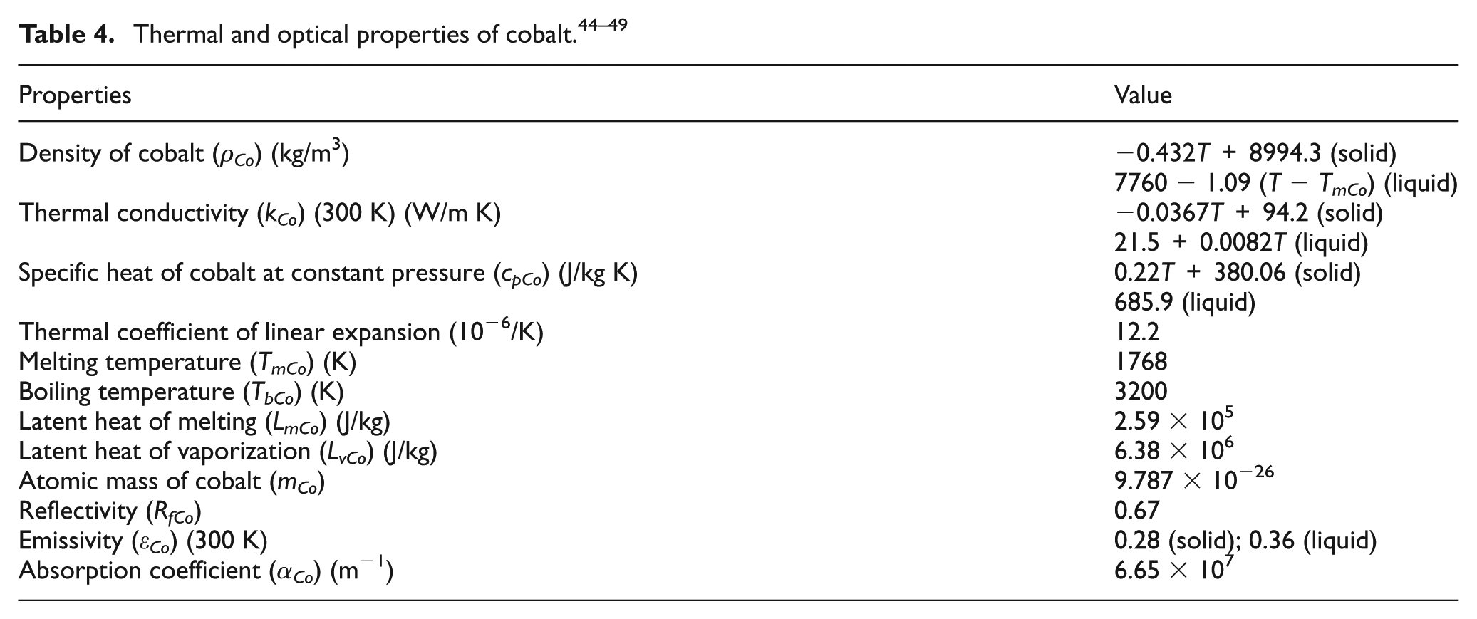
In the computation, the time-dependent problem is solved sequentially, by using the output of nth step as the initial conditions for the (n + 1)th step. In each step of the simulation, computations were performed to calculate the properties of the element and the laser incident position based on the calculated temperature and element coordinates. For the diamond phase, graphitization is assumed to take place if the graphitization probability PG > 1 at the end of a particular step. For the cobalt phase, melting is assumed to occur once the element temperature reaches the melting point, and the liquid-phase ejection depth is then calculated according to equations (13)–(15). The material removal via surface evaporation for the carbon and cobalt elements is estimated according to the Hertz–Knudsen equation. After one step of computation, the new surface (if a material removal took place) is considered and the corresponding new elements are now heated by the laser beam. The element temperature from the previous step is applied as the initial temperature for this step. The boundary conditions are to be updated after each step. The computation repeats until the desired simulation time is reached. The parameters used in the simulation are given in Table 1, while the thermophysical and optical properties of the diamond, graphite and cobalt used in the simulation are given in Tables 2–4.
Parameters used in the finite element simulation.
Thermal and optical properties of diamond grains. 40
Experiment
The experiment was conducted to ablate a PCD of 0.7 mm thickness sintered on a tungsten carbide (WC) substrate. The PCD contains 92% diamond and 2% cobalt with the Knoop hardness of 5000–8000 kg/mm2. A Manlight nanosecond-pulsed Ytterbium laser operating at 1080 nm wavelength and 42 ns pulse duration was used. The laser was randomly polarized due to the birefringence of the optical fibre as supplied by the manufacturer. The laser beam was expanded by an 8X beam expander before being delivered to a lens of 50 mm focal length where it was focused onto the PCD surface, as shown in Figure 5. As for the simulation, four levels of laser pulse energy (E = 0.2, 0.4, 0.6 and 0.8 mJ) were investigated with six levels of the number of laser pulses (N = 1, 2, 4, 8, 16 and 32). The repetition rate and laser beam diameter at the target surface were keep constant at 20 kHz and 20 µm, respectively, where the 20 µm beam size was achieved by adjusting the relative position of the target surface with respect to the laser focal position within the Raleigh range. A full factorial design scheme was used to construct the ablation tests, resulting in 24 test runs each of which was to generate a crater on the specimen. Each test was repeated for three times. The maximum crater depth for each test was measured using a laser three-dimensional (3D) microscope (Keyence VK-X200) with a 0.5-nm vertical resolution, and the average was taken as the final reading. The ablation rate was then obtained from dividing the crater depth by the number of laser pulses applied.
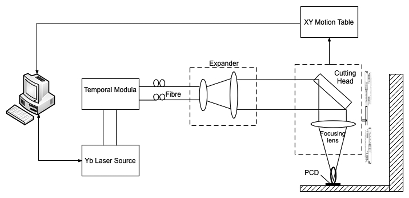
Schematic of the laser modulation system.
Model verification
Figure 6 shows a comparison between the model-predicted and experimental ablation depth per pulse under the corresponding conditions. It can be seen from the figure that without considering the vapour/plasma shielding, the predicted ablation rate increases almost linearly with the increase in pulse energy. The predicted results are much higher than the experimental results, particularly when the pulse energy is greater than about 0.4 mJ. By contrast, the calculated results tend to approach saturation with the increase in pulse energy when considering the shielding effect and show a reasonable agreement with the corresponding experimental data. It is thus apparent that the model considering vapour/plasma shielding effect can be regarded as a good description of the PCD ablation process with nanosecond-pulsed laser radiation. Considering the inherent uncertainty of thermophysical properties of the PCD and the laser output instabilities, the agreement between the model-calculated and experimental ablation depths is reasonable when the vapour/plasma shielding effect is considered.
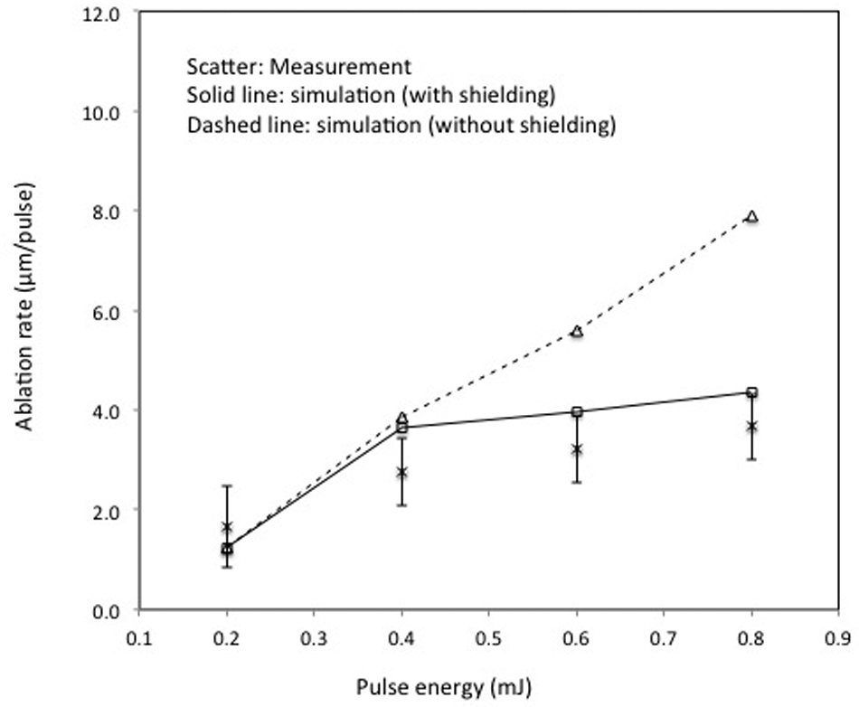
Comparison of measured (the scatter bars show standard deviation) and simulated ablation depth under different pulse energies (laser pulse frequency = 20 kHz).
The differences of the predicted ablation depths with and without considering shielding effect are likely to be due to the absorption of laser energy by the plume formed during the pulse. In the laser ablation process, the target surface temperature can be raised to and maintained at a relatively high value due to the small absorption depth of the target material. Hence, based on the Hertz–Knudsen model, 24 the vaporization flux will be large, generating a relatively high mass density in the small region right above the target surface in the vapour/plasma plume. The high mass density may yield relatively high laser energy absorption and plasma radiation intensity. It is possible that a significant part of the incoming energy is transferred to the plasma and only part of it is dissipated in the target. Obviously, a higher laser pulse energy produces a higher surface temperature and vaporization flux, and hence, a larger radiation intensity zone right above the target surface, enhancing the shielding effect in the laser–plasma interaction. Therefore, without considering the vapour/plasma shielding effect, the model significantly overestimated the ablation depths under the higher laser energy region.
Results and discussion
Crater formation
Figure 7(a) shows the top view of a typical crater machined in the test, while Figure 7(b) depicts the cross-sectional profile in a plane containing the laser beam axis. The crater surfaces formed in single-pulse ablation under different pulse energies are shown in Figure 8, where the micrographs show the ablated area. It can be noticed that under the pulse energy of 0.2 mJ, microstructure changes occurred in the area irradiated by the laser beam. This is because the laser energy was not sufficient to perform a deep cut, but heated the target and caused phase transition.
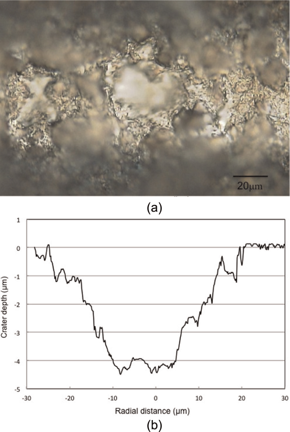
Micrographs of the crater formed in single-pulse ablation when E = 0.8 mJ, D = 20 µm and τ = 42 ns: (a) crater top view and (b) crater cross-sectional profile.
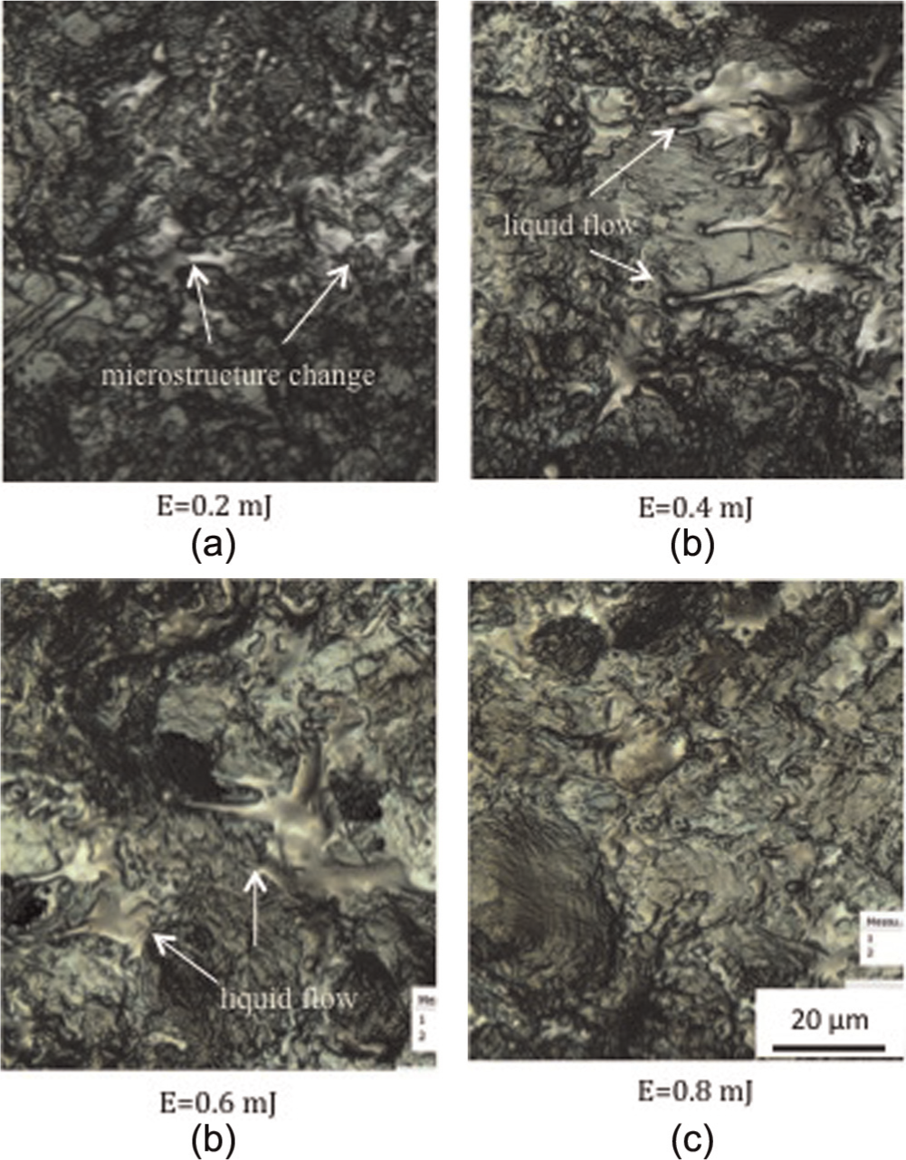
Micrographs of surface morphology under different laser pulse energies (graphs show the central part of single-pulsed laser-ablated area; D = 20 µm and τ = 42 ns): (a) E= 0.2 mJ, (b) E = 0.4 mJ, (c) E = 0.6 mJ and (d) E = 0.8 mJ.
Recast was observed on the crater bottom surface under the pulse energy of 0.4 and 0.6 mJ, as shown in Figure 8(b) and (c), where the sign of liquid flow can be seen. The recast has long tails under the pulse energy of 0.4 mJ, while the liquid appears to be scattered as the laser pulse energy increased to 0.6 mJ. Since the recoil pressure increases almost linearly with the incident laser intensity, as shown in equation (14), the higher recoil pressure under the higher laser pulse energy accelerates the ejection of melted material and its collision with the crater boundary so that part of the melt is broken into small droplets to fly away. After the irradiation of the laser beam, cooling and subsequent solidification took place to form such surface features.
Further increasing the pulse energy to 0.8 mJ resulted in new morphology features, where the bottom surface of the crater has an ablated appearance as can be seen in Figure 8(d), while no obvious melted phase was found. It appears that thermal ablation in terms of the normal vaporization dominates the material removal under higher power densities.
Laser heating and ablation process
Figure 9(a)–(f) shows some simulated temperature profiles on the PCD sample under a single laser pulse irradiation at different time durations from 1 to 50,000 ns, using a 42-ns (full width at half maximum (FWHM)) laser beam with the pulse energy of 0.6 mJ and laser beam diameter of 20 µm.
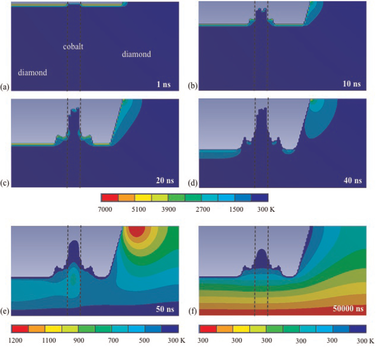
Simulated temporal variations in temperature distribution in the PCD under the pulse energy of 0.6 mJ: (a) 1 ns, (b) 10 ns, (c) 20 ns, (d) 40 ns, (e) 50 ns and (f) 50 µs (the strips within the dashed lines represent cobalt).
Under the condition, the surface temperature reaches the boiling point of diamond and cobalt after 1 ns of the laser irradiation, as shown in Figure 9(a), so that the ablation of diamond and cobalt takes place at this moment. The temperature gradient is gradual from target surface to inside the bulk. Since cobalt has a lower thermal diffusivity than that of diamond, the absorbed heat is conducted into a thin upper surface layer of the cobalt phase within such a short time and leads to a rapid rise in the surface temperature of cobalt, while the temperature in the deeper layers remains unchanged. By contrast, the thermal diffusivity of diamond is much higher; the heat is thus conducted to the deeper layer of diamond so that the surface temperature rises at a lower rate, but the thickness of the heated layer is larger than in cobalt, so is the ablated thickness of the diamond.
With further laser heating, the ablation of diamond continues at 10 ns of the laser irradiation, as shown in Figure 9(b). Meanwhile, the melting of cobalt takes place by this moment and the melted phase of cobalt requires further heating for evaporation.
As the irradiation time increases, the ablation of diamond continues to be faster than the evaporation of cobalt, resulting in a depression in the diamond matrix, as shown in Figure 9(c). Meanwhile, less heat is diffused to the deeper layer of cobalt because of cobalt surface melting and evaporation which takes energy from the target, and cobalt temperature near the cobalt/diamond boundary rises more slowly than the surrounding diamond. Consequently, heat is conducted from diamond to cobalt which decreases the diamond temperature in the vicinity of cobalt/diamond boundary. This temperature decrease reduced the diamond evaporation rate in this region, and thus steps are formed in the diamond matrix in the cobalt/diamond boundary, as shown in Figure 9(b) and (c).
After 40 ns of the laser radiation, the depressions in the diamond phase continue to increase and the cobalt phase stands above that of diamond (Figure 9(d)). Because of the attenuation of laser radiation that incidents on the target surface with vapour/plasma plume shielding, the surface temperature starts to decrease and the material ablation slows down. This is evident from the reduced increase rate of the ablated layer thickness from 20 to 40 ns compared to that from 10 to 20 ns.
At 50 ns (Figure 9(e)), the temperature has decreased because the laser pulse period is 42 ns and there have been already 8 ns in which no laser energy is applied, so that the target temperature decreases because of heat conduction and surface cooling. Finally, the temperature decreases to the ambient condition at 50,000 ns (Figure 9(f)).
Carbon phase transition
Figure 10(a) and (b) shows, respectively, the variations in the graphite layer thickness and propagation velocity with time under different laser pulse energies. As heat diffuses into the target and the associated material is removed, the graphite layer thickness increases with time, as shown in Figure 10(a). It is noted that under all levels of pulse energy, the graphite layer thickness increases initially, and then reaches saturation after a certain period of time depending on the laser pulse energy applied. The time needed to reach the saturation decreases with an increase in the laser pulse energy, while the graphite layer thickness at the saturation stage increases with pulse energy. For instance, the graphitization depth increases over almost the entire laser pulse-ON time under the laser pulse energy of 0.2 mJ, while it reaches the saturation before 20 ns with the 0.8 mJ pulse energy. This is because when the incident energy density is below or just slightly exceeds the ablation threshold, heat is quickly conducted into the PCD and results in thermal graphitization. As soon as the rate of energy consumption (by heat diffusion and for material ablation) and energy absorption from the laser beam becomes equal, the phase transition in the target is sustained.
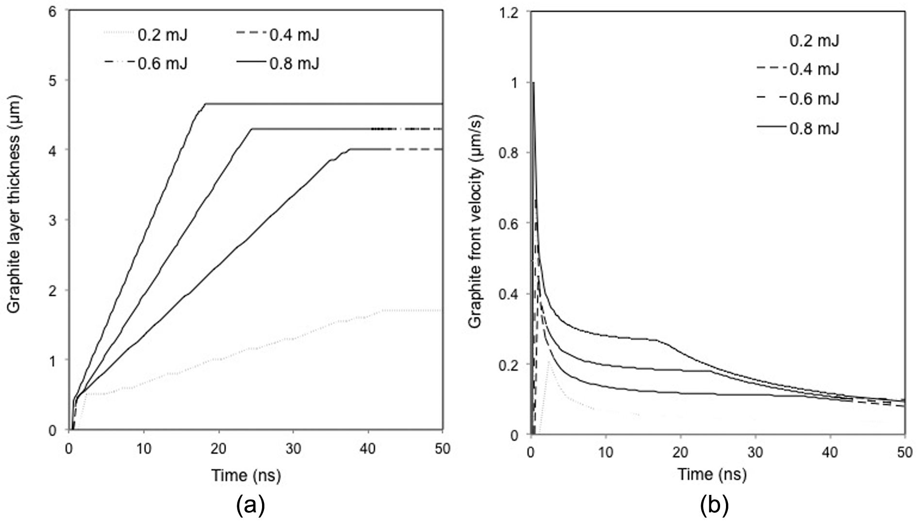
Simulated temporal variations in (a) graphite layer thickness and (b) graphite–diamond interface propagation velocity in PCD under different laser pulse energies (considering plasma shielding effect).
It can be seen from Figure 10(b) that the propagation velocity of graphite–diamond interface towards the solid diamond bulk reaches the maximum value at the very start of the laser pulse under all levels of pulse energy, and then decreases abruptly before decreasing gradually. In general, the thickness of the graphitized layer is determined by the optical absorption depth (α−1) and thermal diffusion length (
Transient temperature field
To investigate the effect of laser pulse energy on the temperature field in the laser ablation process, the temporal evolution of the temperature profile in the PCD along the laser beam axis is given in Figure 11(a) and (b), respectively, for the laser pulse energy of 0.4 and 0.6 mJ, noting that the horizontal axis represents the distance from the surface into the target. It can be seen that under both conditions, the temperature decreases with an increase in the distance from the target surface. This is attributed to the fact that the absorbed laser energy decreases exponentially with an increase in the depth below the target surface, according to the Lambert–Beer law. 19
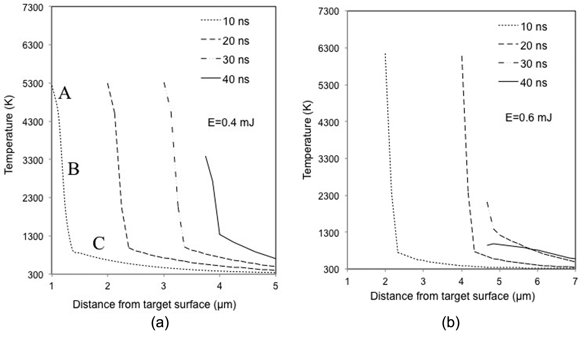
Simulated temperature profiles in PCD along the symmetry axis under different laser pulse energies (considering plasma shielding effect).
It can be noticed from Figure 11(a) that there is a small turning from segment A to segment B on every curve, which suggests that the temperature decreases relatively slowly in the target upper layer as compared to the deeper layer. This is because in the upper layer (segment A) where graphitization has occurred, thermal conductivity of graphite is lower than the diamond in the substrate, which results in a slow heat diffusion from the irradiated region into the target. Furthermore, the higher heat capacity of graphite allows more heat to be accumulated in the irradiated region. As a result, the material in the upper layer gains a higher temperature, and hence yields a higher surface evaporation rate. Material ablation takes heat away from the surface and a smaller thermal gradient results in a slower decrease in temperature in the upper layer regions.
By contrast, since the diamond bulk covered by a graphite layer is beyond the absorption depth, the contribution of the absorbed laser radiation to its temperature rise is not significant. Temperature change along the depth direction is mainly driven by the temperature gradient. The high rate of energy gain from the irradiated area increases the surface temperature, and hence, the temperature gradient next to the surface becomes high, which enhances the heat conduction into the bulk. Thus, the temperature decrease is sharp near the graphite–diamond interface region (segment B). As the distance from the target surface further increases towards the bulk material, the temperature decrease becomes gradual, as shown in Figure 11(a) (segment C), due to the balance between the energy gained from the laser irradiation and the energy transported to the solid bulk through heat diffusion.
Comparing to the condition at 0.4 mJ pulse energy shown in Figure 11(a), the temperatures under the pulse energy of 0.6 mJ are higher at 10 and 20 ns, while there is a sharp decay of the maximum temperature at 30 and 40 ns, as shown in Figure 11(b). This is attributed to the higher evaporation rate at the early stage of the laser irradiation under the 0.6 mJ pulse energy, which enhances plume shielding effect, and thus a higher attenuation coefficient to the laser beam. After 30 ns of laser pulse, the plume that composed of evaporated matters shielded most of the laser radiation from the target, and thus temperature decreases.
Surface evaporation
The temporal variations in ablation depth and evaporation velocity under different laser pulse energies are shown in Figure 12(a) and (b), respectively. For a clearer presentation for the earlier stage of ablation, the change in ablation depth and ablation velocity from the start to 5 ns is shown in Figure 12(c) and (d). It can be seen from Figure 12(c) that material ablation initiates immediately after the laser beam is applied and a lower laser energy (e.g. 0.2 mJ) takes a longer time to cause material removal than a higher pulse energy. A maximum depth appears to exist for the laser pulse energy applied and an increase in the pulse energy increases the maximum ablation depth (Figure 12(a)).
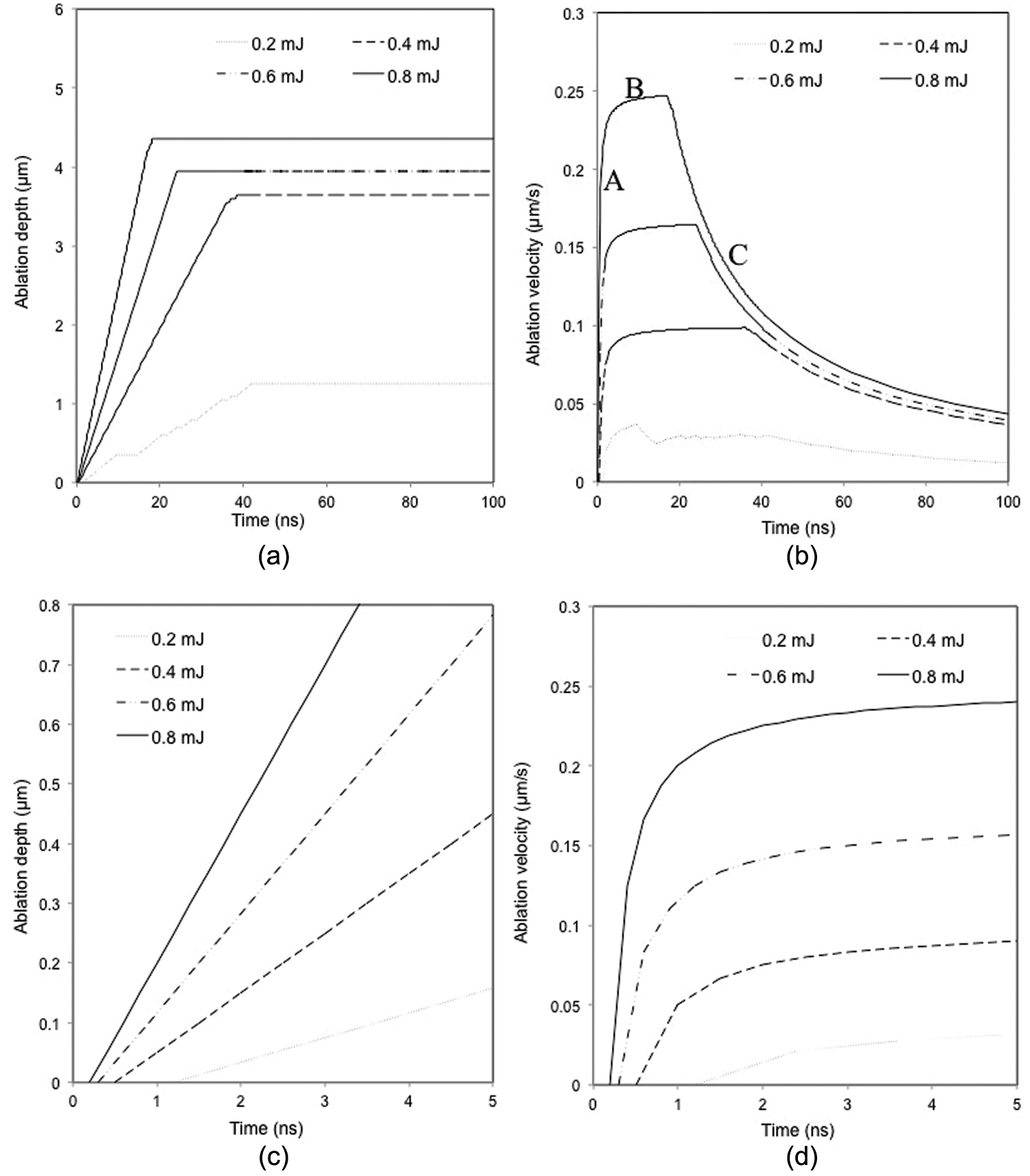
Simulated temporal variation in (a) ablation depth and (b) evaporation velocity under different laser pulse energies. Magnified view of (c) ablation depth from 0 to 5 ns and (d) evaporation velocity from 0 to 5 ns (considering plasma shielding effect).
It is noticed from Figure 12(b) that the ablation velocity (or the velocity of material evaporation) increases rapidly at the start of laser irradiation (segment A), and then rises gradually at segment B until it reaches the maximum value, and finally decreases at segment C. Ablation starts when the laser fluence exceeds the threshold for ablation. Although the maximum energy absorbed from the irradiated area takes place at the surface of the target, the rate of evaporation is limited because of the high value of the latent heat of evaporation, so that the increase in evaporation (or ablation) velocity becomes slow over a period from segment A to segment B shown in Figure 12(b). During the target material evaporation, a vapour/plasma plume is formed above the target surface which blocks a significant part of the incoming laser energy from being dissipated into the target, and the laser pulse energy absorbed by the target thus decreases, so does the ablation velocity as shown in segment C in Figure 12(b). It is further noticed from Figure 12(b) that the evaporation velocity is higher under a higher than a lower laser pulse energy, as may be expected.
It can be seen from Figure 12(b) that the decrease in ablation rate starts earlier with a higher than a lower pulse energy. This may be due to the more significant vapour/plasma shielding effect under a higher laser energy where mass material evaporation takes place. 50 During the laser irradiation, a higher laser pulse energy produces a higher target surface temperature and a higher vaporization flux, and thus a larger vapour/plasma intensity zone right above the target surface. As a result, some laser energy cannot reach the target surface, but is absorbed to heat the plasma. Meanwhile, the evaporation takes some heat away from the target surface, so that the overall effect causes the surface temperature and the evaporation rate to decrease. A higher pulse energy results in a quicker temperature increase in the target and requires a shorter time to cause material evaporation, and hence an earlier start of decrease in the ablation rate.
Cobalt melting and ejection
The change in the cobalt melting depth with time is shown in Figure 13 under different laser pulse energies. At the early stage of laser irradiation, the heat absorbed from the irradiated area is conducted to the solid bulk and causes the cobalt to melt. At the interface of the liquid and solid cobalt, the rate of heat diffusion from the liquid to solid phase is high, thus increasing the temperature in the solid region next to liquid. Moreover, the melting of cobalt increases the energy gain from the irradiated area due to the large latent heat of melting of cobalt and enhances the solid–liquid transition.
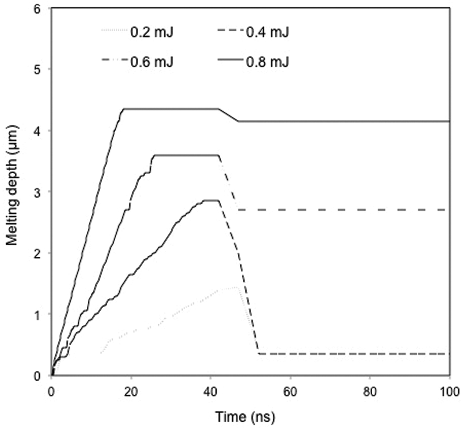
Simulated temporal variation in cobalt melting depth (considering shielding effect).
It is noticed that the melting depth (melting layer thickness) reaches a maximum value after a period of time depending on the pulse energy applied where a higher pulse energy requires a shorter time to arrive at the maximum because of more energy input. With further laser irradiation, part of the heat absorbed from the laser is used for material evaporation which together with the vapour/plasma shielding effect results in a reduced amount of energy transferred into the solid bulk, and hence a reduced melting depth. For the high pulse energies applied (such as 0.8 mJ), the removal of cobalt phase is mainly through evaporation because of more energy input, while the ejection of molten cobalt through a recoil pressure from the melting process dominants the cobalt removal process under relatively low laser pulse energies.
After the laser pulse of 42 ns, there is no further energy input so that the temperature decreases and re-solidification of cobalt takes place. As a result, the melting depth decreases rapidly, as shown in Figure 13. It is noticed that the reduction in melting depth is smaller under a higher than a lower laser pulse energy. This is possibly due to the higher latent heat contained in the liquid to build evaporation with a higher pulse energy that helps to maintain the liquid phase for some time after the laser irradiation. The difference between the maximum melting depth during the pulse-ON period and the melting depth during the pulse-OFF period shown in Figure 13 should represent the amount of re-solidified cobalt on the ablated surfaces after the irradiation of one laser pulse.
Conclusion
An FE model for single-pulsed laser ablation of PCD has been developed, considering the diamond and cobalt phases in the PCD. The model has been verified by comparing the model-calculated ablation depth with the corresponding experimental data which showed a good agreement when the vapour/plasma shielding effect was considered. From the experimental and simulation studies, three material removal mechanisms have been identified, namely, the graphitization of diamond for all the energy levels considered, surface evaporation under higher laser pulse energies and ejection of molten cobalt under lower pulse energies.
The removal of cobalt has been found to initialize earlier than that of diamond under a laser irradiation. However, as the melting of cobalt consumes a large amount of the absorbed laser energy, the MRR for cobalt is smaller than diamond. The graphitization of diamond results in heat accumulation in the surface region which leads to a high surface temperature, and thus a high evaporation rate. It has been noted that while increasing laser pulse energy raises the ablation rate, it enhances the plasma shielding effect which decreases the laser intensity reaching the target, and consequently reduces the efficiency of energy use.
Footnotes
Appendix 1
Declaration of conflicting interests
The authors declare that there are no conflicts of interest.
Funding
Q.W. would like to thank the China Scholarship Council for providing a scholarship for her PhD study.