
Abstract
The increasing use of diamond cutting tools necessitates the development of compatible fabrication technologies for the diamond tools, especially for three-dimensional surfaces with micron scale accuracy and good surface quality. In this article, the formation mechanism of surfaces milled using a nanosecond pulsed laser on polycrystalline diamond and the effect of process parameters on the milling performance such as material removal rate and surface integrity are investigated based on a statistically designed experiment. It is shown that laser milling is a viable technology for three-dimensional processing of polycrystalline diamonds with good machining rates and acceptable surface quality. A microscopy analysis indicates that diamond graphitization can occur on the milled surfaces, and laser pulse energy and pulse overlap have a significant effect on the milled surface morphology. Characterization of the machined surface/subsurface is conducted using Raman spectroscopy, and the relationships between damaged surface layer thickness and process parameters are discussed. It is found that an optimum pulse overlap together with moderate pulse energy may be used, while the scan overlap should be selected in the vicinity of its optimum value at around 50% for a good surface quality while maintaining a high material removal rate.
Keywords
Introduction
With the increasing development and utilization of super-hard, high-strength and high-performance materials in many fields, such as diamond cutting tools, conventional machining can no longer meet the processing needs, mainly due to the unavailability of ultra-hard tool materials for the economical and effective machining of these difficult-to-machine materials. Since the development of the relatively simple polycrystalline diamond (PCD) synthesis methods, significant research efforts have been devoted to the application of this material. With highly attractive properties, such as extremely high hardness, high fracture toughness and high degree of chemical inertness, PCD has been widely used as a tool material for machining difficult-to-machine materials such as glasses and ceramics as well as for drill bits in oil and gas exploration.1–3 For these applications, three-dimensional (3D) features on the PCD tools with good dimensional accuracy and surface quality are required. Thus, developing an appropriate micromachining process for PCD tool fabrication is imperative. For this purpose, a brief review of the work undertaken on this topic is conducted first.
Background and review of previous study
Some grinding and lapping processes for hard–brittle materials may be used for the precision machining of diamond; 4 however, although the needs for dimensional accuracy and surface finish may be satisfied, long processing time and high machining costs account for 60%−90% of the total product cost. 4 Electrical discharge grinding (EDG) and wire electrical discharge machining (WEDM) have been used for the fabrication of PCD tools in recent years.5–7 A study 8 to apply EDG for PCD has found pit matte and diamond grain peeling on the workpiece surface after the EDG process, and the subsurface damage was up to 50 µm. The same phenomenon was observed by Kozak et al., 9 who reported that the surface defect was caused by the erosion of cobalt binder and the removal of diamond grains, which were also the dominant mechanisms in WEDM of PCD. Liu et al. 10 proposed an electrical discharge milling process for PCD using a rotary toothed tool and generating pulse discharges mechanically, which improved the productivity and reduced the cost as compared to WEDM and EDG, but the machining dimension and surface features were restricted by the characteristics of electrode tools. It appears that the low productivity and poor surface finish associated with electrode tool fabrication limit the application of electrical discharge machining for PCD materials. 11
Laser machining as a noncontact machining process appears to be a promising method for PCD processing due to its high machining accuracy, high efficiency and other advantages such as no tool wear and easy working environment over the other machining processes.12,13 In recent years, some important investigations using laser machining processes14–16 have been undertaken in an effort to achieve good surface quality on diamond or ceramic tools, as well as to acquire an understanding of the material removal mechanisms in order to predict, control and optimize the laser ablation processes. Research study has also been carried out on theoretical and modeling studies for exploring the laser ablation mechanisms and the optimization of laser machining process.17,18 It is noted that the work on laser machining processes has been primarily directed toward applications in drilling,19,20 cutting 21 and microstructuring, 22 with little attention paid to the surface 3D shaping process.
A 3D laser milling technique by overlapping multiple laser-scanned grooves was first proposed by Wallace and Copley. 23 In their study, the feasibility of this technique in terms of the material removal rate (MRR), surface roughness and complex feature shaping was studied and compared with the traditional grinding process. Laser milling was also studied for creating small and complex structures in different materials,24,25 including ceramics 26 and PCD. 27 Despite these good efforts, the studies and associated knowledge in terms of the machining performance and process characteristics in pulsed laser milling of PCD are still in severe dearth. 28 Furthermore, the extensive heat induced by a laser source can result in thermal damages to workpiece surface and subsurface. Ultrashort pulsed (e.g. femtosecond) lasers have been used for precise and damage-free processing, 29 but their capability makes them unsuitable for high MRR at this stage of development. Although a hybrid laser–waterjet micromachining technology was recently developed 30 for near damage-free machining with high MRR, more studies are needed before this technology can be used in industry. It is thus evident that a continued effort is required to study the laser milling process for the effective and efficient machining of PCD into 3D geometry.
In this article, an experimental investigation of the formation mechanisms for surfaces milled by a nanosecond pulsed laser is present. The milling performance as assessed by surface roughness and MRR and the effect of process parameters are studied based on a statistically designed experiment. Raman spectroscopy analysis is employed to study the thermal damage on the milled surfaces and subsurfaces. Statistical analysis of the relationships between surface damage layer thickness and the process parameters, and the selection of the process parameters for milling the material are also discussed.
Experiment
The experimental setup is shown in Figure 1. A solid-state ytterbium fiber laser, operating at the wavelength of 1080 nm with 50 ns pulse duration, was emitted from a single-mode fiber through a collimator. The laser can be pulsed at a repetition rate ranging from 20 to 100 kHz at a random polarization. The maximum pulse energy of the laser at 20 kHz repetition rate is 1.0 mJ with a Gaussian profile. The 0.5 mm laser beam from the fiber was expanded by an 8X beam expander before being delivered into a laser cutting head with a lens of 50 mm focal length. With this setup, the diameter of the laser spot size at the focal plane at 1/e 2 of the peak intensity was 17.2 µm. The laser head was mounted on a precision X–Y motion control stage to enable two-dimensional movements of laser beam with the accuracy of 1 µm over 300 mm traverse distance. A manually operated precision stage in the Z direction was used to adjust the focal plane position of the laser beam with respect to the workpiece. A red aiming beam that was collinear with the laser allowed the laser beam to be spotted.
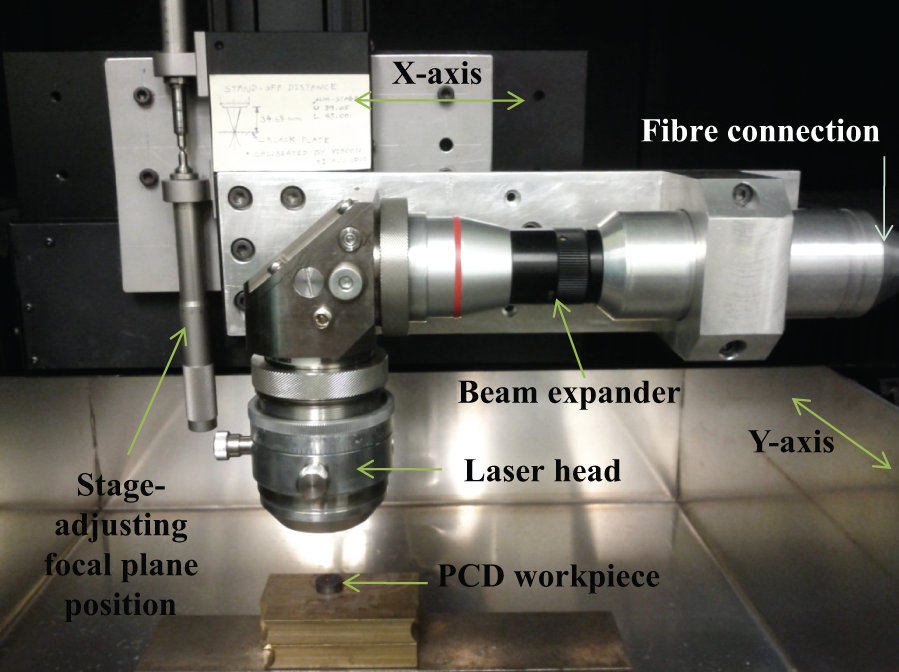
Experimental setup for laser milling of PCD.
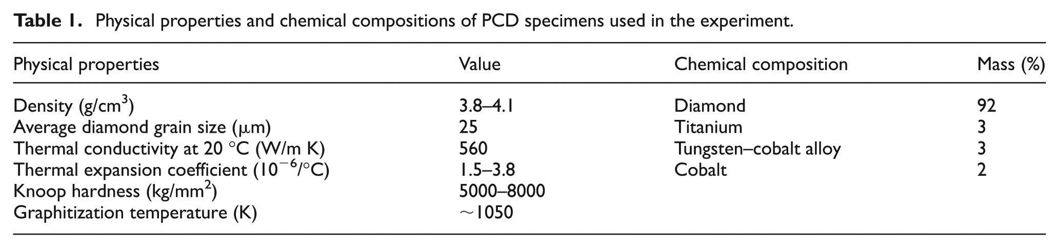
The experiment was conducted on a thermally stable PCD composite with the average diamond grit size of 25 µm. The specimens were in cylindrical shape with the diameter of 13 mm and the PCD thickness of 0.7 mm, sintered on a tungsten carbide (WC) substrate. The physical properties and chemical compositions of the specimens are given in Table 1.
Physical properties and chemical compositions of PCD specimens used in the experiment.
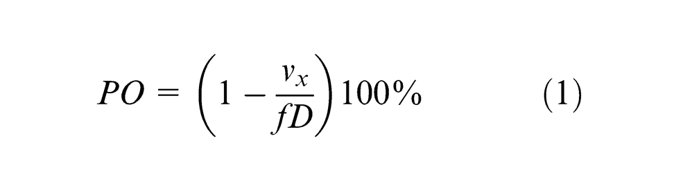
Four process parameters that were considered to be the significant and easy-to-adjust parameters as identified in a trial study were selected as variables, that is, pulse energy (E), pulse overlap (PO), scan overlap (SO) and number of passes (NP). In this study, pulse overlap is defined as the overlap of the laser beams on the work surface in two consecutive pulses during the laser traverse motion, while scan overlap is that between the two laser beam tracks in two consecutive traverse motions (with the distance of a cross-feed) in order to create a milled surface, as shown in Figure 2 where traverse motion is made along L and the cross-feed motion is made along W. Pulse overlap is dependent on laser beam traverse speed vx, laser repetition rate f and focused laser beam diameter D, such that
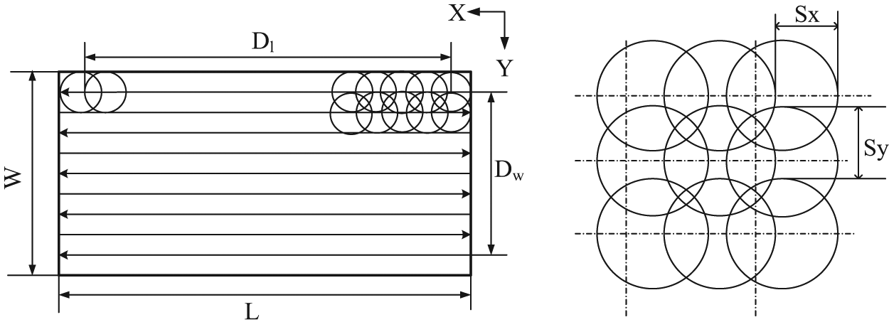
Schematic description of the milling condition.
The number of passes refers to the number of times that the laser was used to scan over the same milled surface (using the same process parameters in this study). The levels and values of each of the parameters selected are given in Table 2. The selection of pulse overlap and scan overlap was based on the appropriate range of beam traverse speeds and a trial study. In addition, one level of laser repetition rate (20 kHz) and one level of beam diameter (20 µm) at the specimen top surface were considered. This beam diameter was made by adjusting the focal plane position (i.e. setting the position of laser focal point at above the specimen surface so that the beam diameter at the specimen surface becomes 20 µm at 1/e2 of its maximum intensity). Using a full-factorial experimental design, 192 combinations of the process variables were considered. For each milling test, a 2 mm × 1 mm rectangle pocket was ablated on the PCD specimen.
Parameters used in the laser milling experiment.

All test specimens were cleaned in an ultrasonic bath for 15 min after laser irradiation to remove the contamination on the machined surface and then rinsed with water and air-dried. The surface characteristics in terms of the surface morphology and surface roughness were examined using a 3D laser scanning microscope (Keyence Model VK-X200) at a 0.5 nm resolution. Five measurements of the roughness (centerline average Ra) at the cutoff of 0.25 mm were performed for each milled surface, and the average was taken as the final reading. Similarly, the depth of milled pockets was measured using the same Keyence 3D microscope, and the MRR was evaluated from the measured depth. In addition, Raman spectra of carbon phase on the surfaces and subsurfaces were obtained using a Renishaw inVia Raman Spectrometer that was coupled with a 514 nm Argon ion laser source. The laser spot was focused to an area of 1.5 µm in diameter through a 500× magnification objective lens. All spectra were collected at 25 mW laser power in the standard mode, and the acquisition time for each measurement was 3 s.
Surface formation mechanisms in milling process
A laser-milled surface on PCD shown in Figure 3 indicates that the overall appearance of the surface is of good quality, while the thermal damage in the subsurface will be discussed late in this article. From a morphological observation of the milled surfaces, as shown in Figure 4, three characteristic surface morphologies may be categorized in this study. It has been found that the formation of surface morphology is mainly affected by the pulse overlap and pulse energy. As shown in Figure 4(a), only the material on the grain boundaries was ablated and there was no clear depth of cut formed when the laser energy was too low to achieve material ablation. As the laser pulse energy or pulse overlap increases, the machined depth increases and the striations along the traverse direction become apparent, as shown in Figure 4(b) and (c). As a consequence, the milled surface becomes rougher because of the inhomogeneity in the absorbed energy caused by variations in the local optical reflectivity of the surface and multiphase of the PCD target. With a further increase in pulse energy and pulse overlap, the milled depth increases, and the graphite clusters and mass oxidation were found on the milled surface due to the increased heat accumulation, as shown in Figure 4(d). More details of the surface formation mechanisms will be further analyzed in the following.
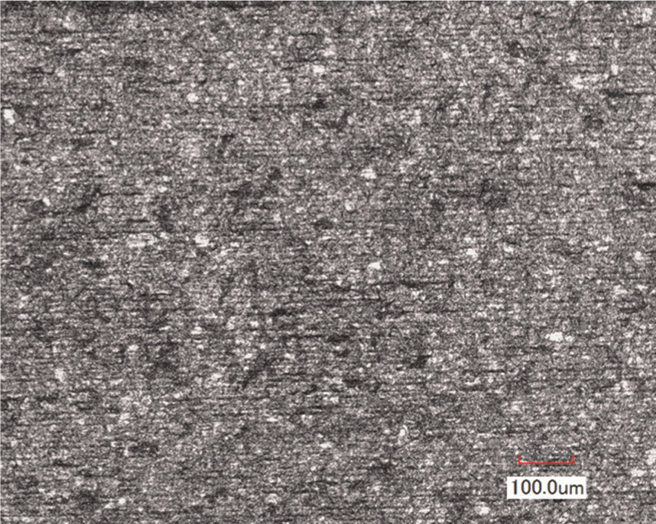
Sample PCD surface milled by laser (PO = 65%, E = 0.2 mJ, SO = 70% and NP = 1).
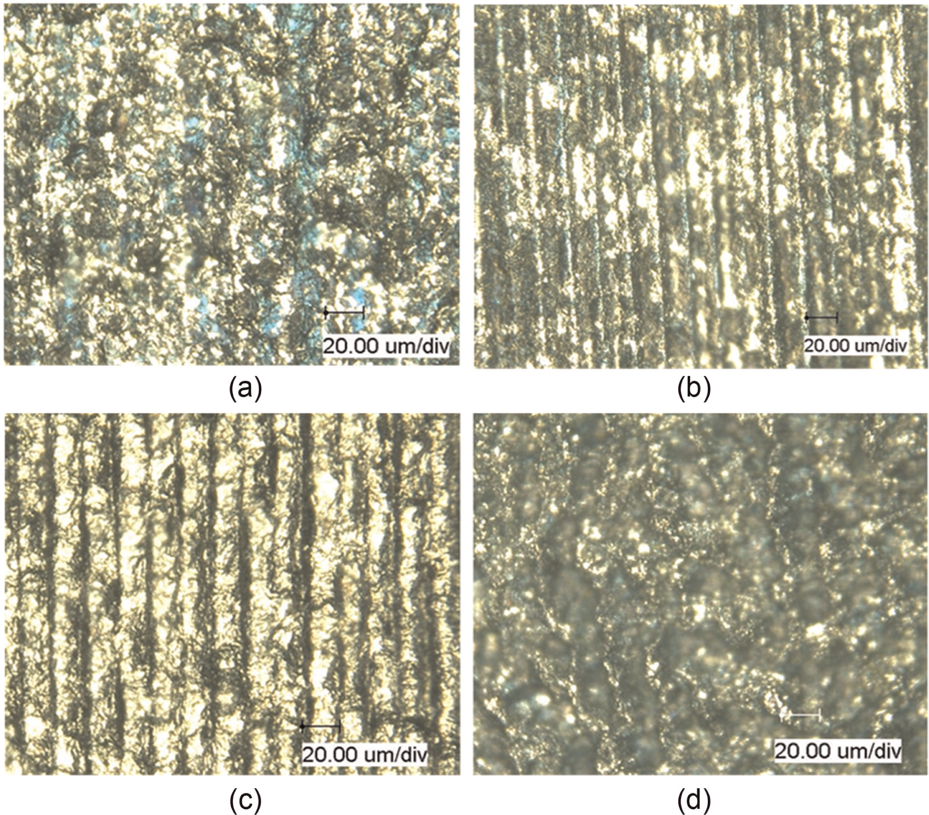
Micrographs of laser-milled surfaces: (a) PO = 65%, E = 0.2 mJ, SO = 10% and NP = 1; (b) PO = 75%, E = 0.4 mJ, SO = 10% and NP = 4; (c) PO = 95%, E = 0.2 mJ, SO = 70% and NP = 2 and (d) PO = 85%, E = 0.6 mJ, SO = 10% and NP = 2.
Graphitization of diamond
Nanosecond-pulsed infrared laser machining is mostly driven by thermal ablation where oxidation and evaporation of carbon are usually responsible for the material removal. 31 In this study, some selected material surfaces were examined using the Raman spectroscopy technique before and after laser irradiation to assess the carbon phase transformation during the laser milling process. The Raman spectrum obtained from the initial surfaces shown in Figure 5 presents a broadband at 1333 cm−1, which is considered to represent diamond, as the sharp Raman peak at 1332 cm−1 is the characteristic of diamond structure. The 1 cm−1 shift to the higher wave number may be related to the stress state of the PCD specimen.32,33 After the laser milling process, the Raman spectrum of a typical surface shown in Figure 5 consists of a D band centered at 1353 cm−1 (varying between 1345 and 1356 cm−1 for other samples) and a G band centered at 1591 cm−1 (varying between 1580 and 1591 cm−1 for other samples). The disappearance of the peak at 1333 cm−1 and the presence of two intense bands indicate the removal of the diamond structure and the formation of graphite on the milled surface, respectively. 34
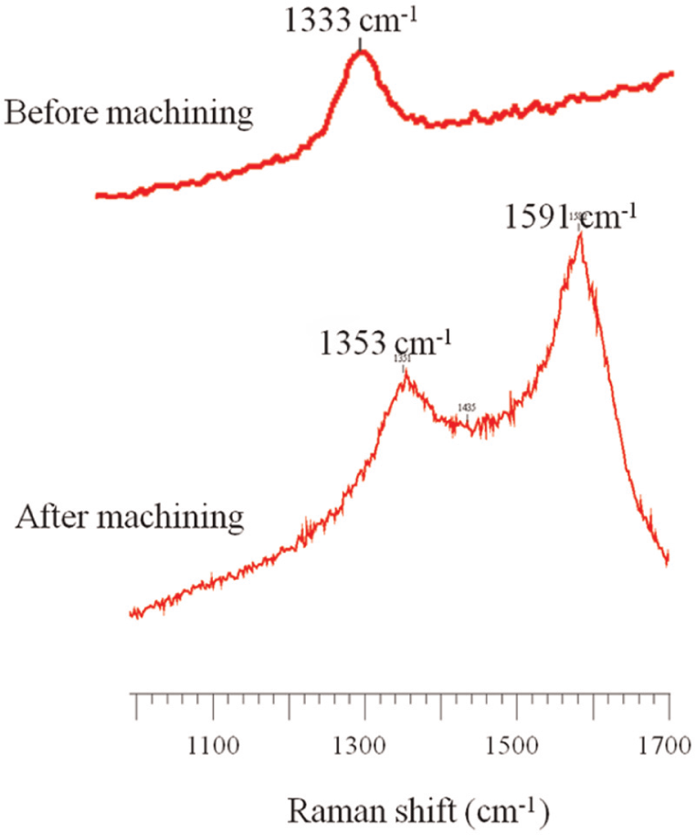
Typical first-order Raman spectra for a PCD surface before and after laser irradiation.
As shown in Figure 4(a), only the material on the grain boundaries was ablated and there was no clear depth of cut formed when the laser energy was too low to achieve material ablation. It may be understood that at a small laser intensity, the laser heat is not sufficient to perform a cut in the material, but heating the surface layer and causing phase transition. In this case, the impurities and defect originating from the PCD fabrication process may have a higher thermal absorptivity and lower ablation threshold in localized areas than the rest. Thus, the accumulation of heat on the target grain boundaries where imperfection concentrates will result in a slow transition and oxidation of diamond grains, which may become the dominant mechanism of material ablation at the PCD surface. For the sample shown in Figure 4(a), no debris or re-deposition on the ablated surface was found; only the graphitic carbon grains appeared after laser irradiation. This suggests that there was no mass ablation at this level of laser fluence, except for thermal damage and chemical reaction.
Mass material removal in a single-pass milling operation requires the laser irradiation to have the energy density above the ablation threshold for diamond. It has been noted that in a multi-pass milling process, the accumulated depth of ablation increases with an increase in the number of passes at the pulse energy that is insufficient to remove diamond grains in a single-pass milling. It is believed that the surface graphitization generated in previous passes facilitates material removal in the subsequent pass of a multi-pass process requiring a low-intensity laser irradiation.
Surface evaporation
With a larger pulse overlap or pulse energy, material removal was obtained and the milling traces were visible, as shown in Figure 4(b) and (c). The laser heating of a PCD target results in a temperature rise and material ablation. The temperature rise stimulates the carbon phase transition and cobalt melting while the ablation creates a milled surface. When a larger pulse overlap is used, there is a longer accumulated exposure time for the laser irradiation to take place that results in more material removal and a deeper cut. A “V” shape groove in each traverse is likely to be formed due to the Gaussian profile of the laser beam, as shown in Figure 6. When a Gaussian laser beam profile is applied over the target, ablation occurs where the local fluence F is greater than threshold fluence Fth and the maximum ablation dmax locates in the middle of the laser energy distribution. Between the damage (or graphitization) and ablation thresholds (as denoted by
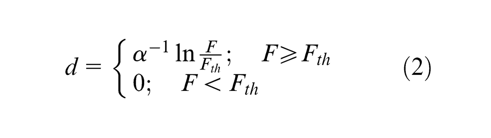
where α is the absorption coefficient of the PCD target.
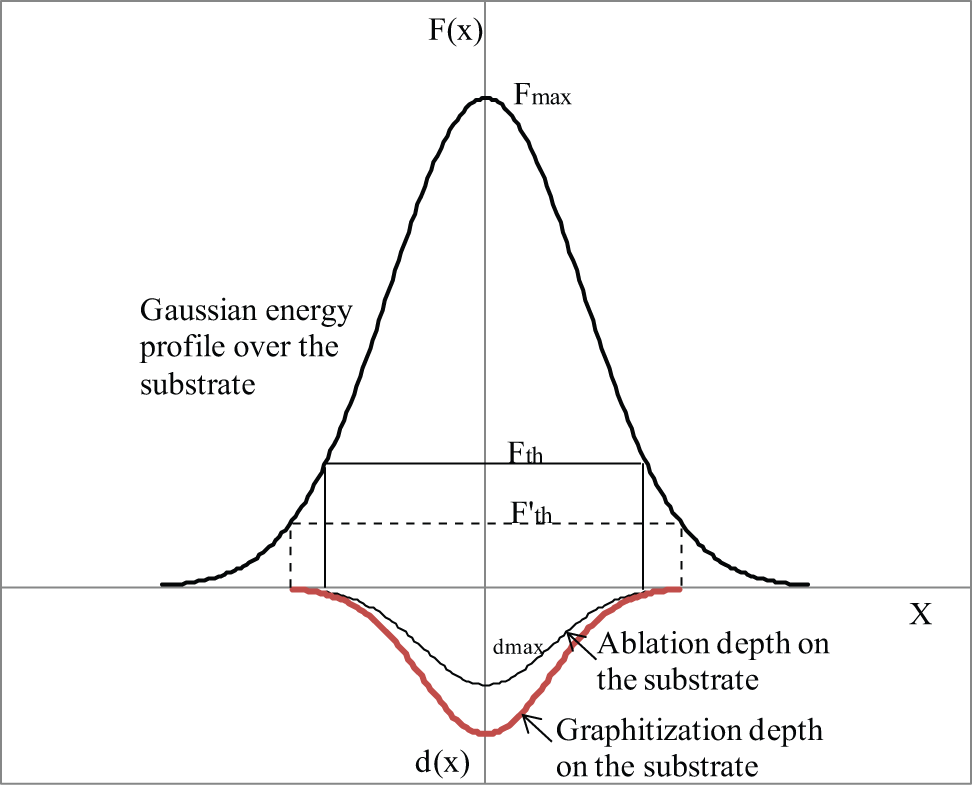
Irradiation over the target material by a Gaussian profile laser beam.
As the laser pulse energy increases, the pocket depth increases; the milled surface becomes rougher due to the thicker resolidified material and debris re-deposition, and a periodic structure becomes apparent. Furthermore, the strong interaction of the laser pulse with the laser-induced plasma may result in rougher surface. It is found that relatively smoother surfaces were obtained using the laser pulse overlap of 75% in this study. As higher pulse overlap means more laser pulses heating the target, which allows higher laser energy depositing into the solid and ablating the protruding diamond grains, as shown in Figure 4(b), smoothening of the surface occurs. With a further increase in the pulse overlap, each traverse pass leads to the appearance of deep valley and therefore increases groove marks and surface roughness, as shown in Figure 4(c). Based on the experimental results, the periodic structural patterns on the milled surfaces are apparent in the multi-pass milling process with the pulse energy and pulse overlap used. Once a periodic structure is formed, the laser may strike on the side of the structure (mostly the composition of grooves) in the following pass with a high angle of incidence; the local laser energy absorbed by the target may be reduced if multiple reflections or scattering of the incident beam takes place. If the laser is reflected into some parts of the groove valleys, it raises the local incident intensity and increases the local ablation depth. This process intensifies and the periodic structures become more apparent as the number of passes increases.
Liquid-phase ejection due to surface tension and recoil pressure
The morphological observations shown in Figure 7(a) indicate that the cobalt is removed by vaporization and liquid cobalt expulsion due to a recoil pressure. As a result of this process, a resolidified phase is formed on the irradiated surface, as shown in Figure 7(a). As the material removal in cobalt takes place by evaporation, the removed material exerts a force over the surface area that drives out the liquid cobalt. This force is caused by the surface tension gradients from an inhomogeneous temperature distribution at the liquid surface or by the recoil pressure exerted by the expanding ablation plume. The recoil pressure produced by the evaporated mass flow generates a uniform pressure over the irradiated surface, which ejects the molten material in a direction parallel to the surface of the cutting front. The magnitude of this force, pv, is proportional to the laser fluence, F, required for machining a certain depth, d, that is

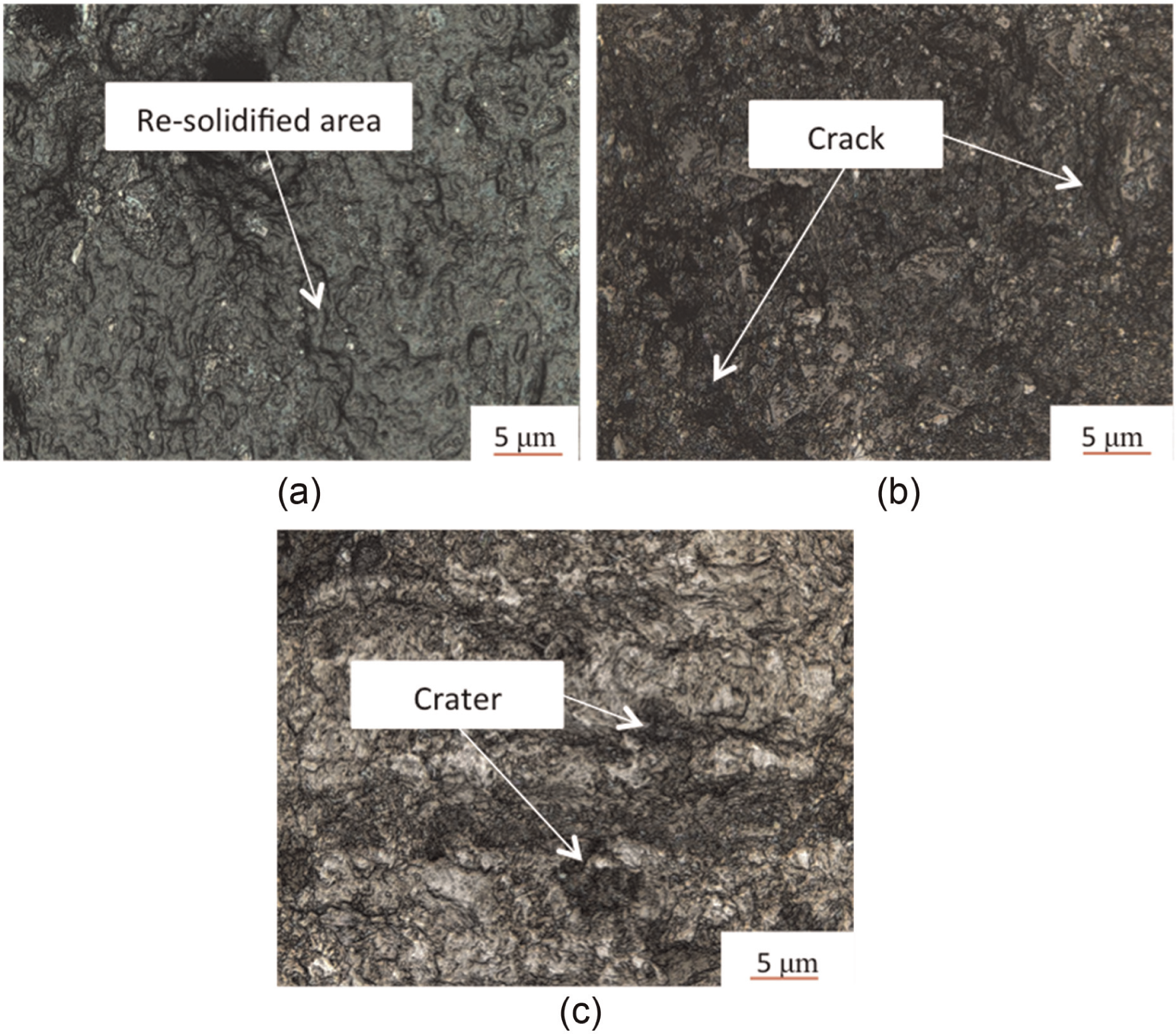
Details of surface morphology: (a) PO = 95%, E = 0.2 mJ, SO = 50% and NP = 1; (b) PO = 65%, E = 0.8 mJ, SO = 10% and NP = 4 and (c) PO = 85%, E = 0.4 mJ, SO = 30% and NP = 2.
The spatial variation of a Gaussian beam intensity generates a radial pressure gradient acting on the irradiated area, and the pressure increases with the change of this laser irradiance. This laser-induced pressure gradient at the evaporation front pushes the local material radially outward. The ejected material can then either flow away along the walls of the crater or be trapped in the irradiated area and resolidified after the laser pulse. In either way, as long as the ejected material does not obstruct the central part of the beam, the material ablated at the center of the beam increases. The total ablation thus becomes the sum of two contributions: a thermal ablation caused by evaporation and a liquid-phase ejection caused by a vapor pressure. Since the composition of cobalt is 2% of the total mass, there is not a large area of liquid flow formed on the milled surface, but the melting and ablation of cobalt will decrease the diamond-bonding forces and change the laser–target interaction.
Thermomechanical ablation
When both a larger pulse overlap and a higher pulse energy were used, the milled pockets showed a different surface morphology; the surface was covered with a thick oxidized layer and scattered craters were found on the irradiated surface due to the detachment of diamond grains, as shown in Figure 7(c). Morphological observations show that an increase in pulse overlap causes a significant increase in surface oxidation. Specifically, this study shows that a massive surface oxidation occurred with the pulse overlap of 85% and 95%, when pulse energy higher than 0.6 mJ. This is attributed to the slower traverse speeds corresponding to higher pulse overlaps, where the heat deposited by the laser into the workpiece surface layer is high, resulting in diamond phase transition propagating deeper into the specimen surface. Furthermore, with the combination of a higher pulse overlap and a higher pulse energy, the evaporation and expulsion removal of liquid cobalt lead to a thermomechanical ablation of diamond grains, and a damage is initiated by the lattice strain due to a large thermal gradient, followed by crack formation at the defects or grain boundaries, as shown in Figure 7(b).
Milling performance
Effect of process parameters on MRR
A thorough understanding of the effects of the various process parameters on the MRR is essential for the selection of these parameters. In this study, the ablation depth was measured and used to calculate the MRR. Due to the uneven surface of the processed pockets, the measurement at three locations on each pocket was made for the milled depth and the mean value was taken. The MRR was evaluated using the following equation

where L and W are the length and width of the milled pocket, respectively, as shown in Figure 2; Z is the measured pocket depth and t is the total processing time for the milled pocket. From Figure 2, the pocket length and width can be expressed as

and

where Dl and Dw are the distances traversed by the laser beam in the X and Y directions, respectively, and D is the diameter of the laser at the target surface. The total processing time required to form the pocket is given by
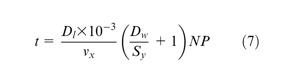
In the above equation, vx is the laser traverse speed, so that the term Dl/vx is the time required to complete a traverse motion, and Sy is the distance between two consecutive traverse motions (or cross-feed) along Y direction, as shown in Figure 2, which can be expressed as Sy = D(1 −SO).
The effect of pulse overlap on the MRR is shown in Figure 8(a). It is noted that in general, MRR decreases with an increase in pulse overlap, although there appears to be an initial increasing trend with a small rate of change under lower pulse energies. This may be attributed to the relation between pulse overlap and traverse speed (or the processing time), as shown in equation (1). With an increase in pulse overlap, MRR turns to increase as a result of a higher energy input and a faster heating rate. However, the pulse overlap is achieved by reducing the traverses speed, which has an adverse effect on the MRR, and overall, MRR shows a decreasing trend. Nevertheless, at lower pulse energies and lower pulse overlaps, the increase in pulse overlap appears to be more than enough to trade-off the adverse effect of slow traverse speed so that MRR appears to increase initially with pulse overlap.
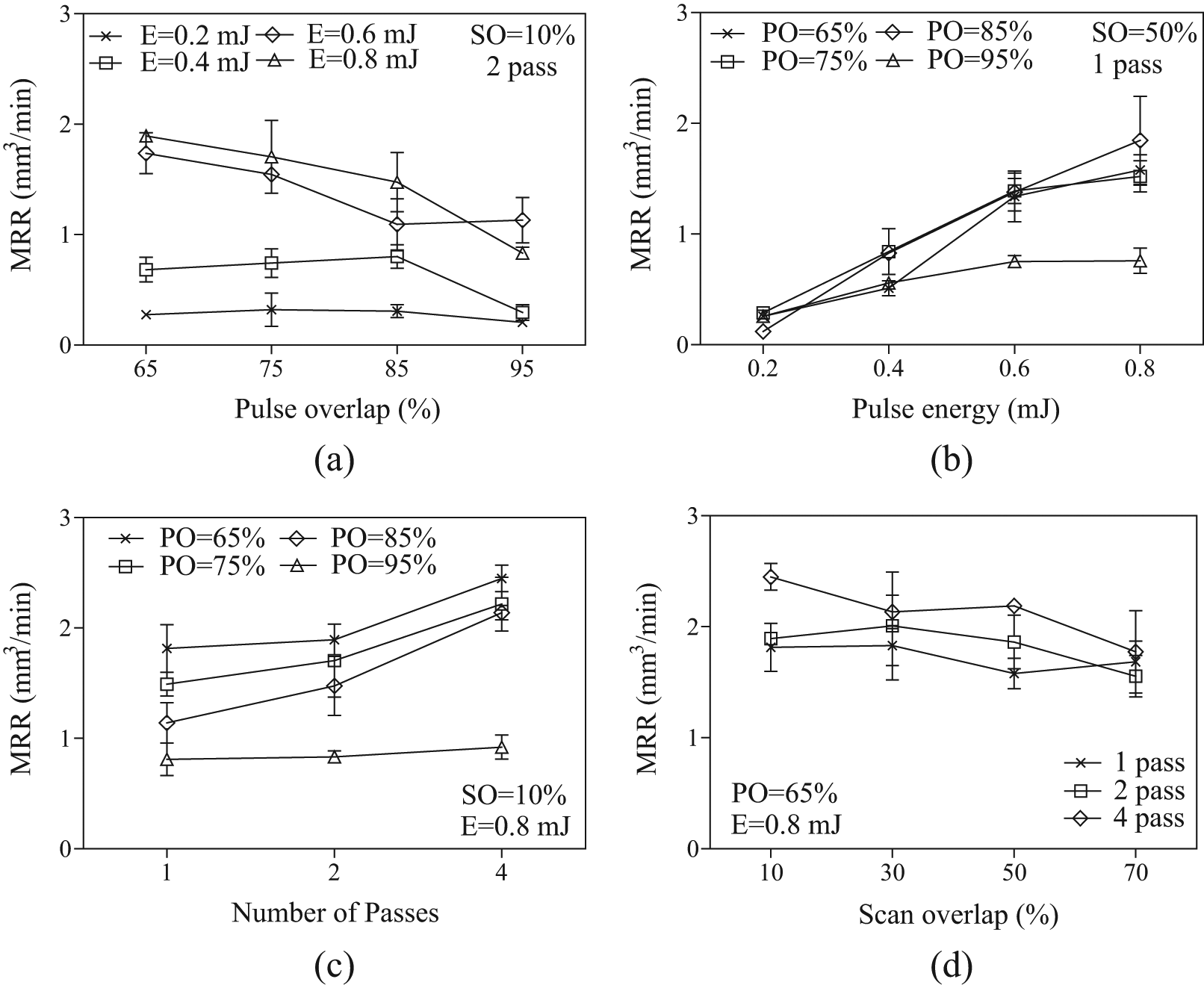
Effect of milling parameters on MRR (the scatter bars show the standard deviation).
As shown in Figure 8(b), MRR increases with the increase of pulse energy as a result of an increased intensity of laser irradiation. At the 95% pulse overlap, MRR appears to be low, which is consistent to what is shown in Figure 8(a).
The effect of the number of passes on MRR is shown in Figure 8(c). In general, MRR increases with an increase in the number of passes, although such an effect is not significant under the pulse overlap of 95%. This may be attributed to the relation between the volume of material ablated and the total processing time, as shown in equation (7). In the case of multi-pass milling, the total processing time increases proportionally with the number of passes. Meanwhile, it has been found from the experiment that the depth milled in a two-pass milling is more than doubled the depth formed in a single-pass milling with the same processing parameters, and a similar trend was found when comparing the depth between a two-pass and a four-pass milling. It may be understood that a part of the laser energy in the first pass transforms a surface layer of diamond to an opaque graphitic carbon with reduced thermal conductivity; the laser in the subsequent milling pass easily heats and removes the graphitized layer. Each subsequent pass takes the same action to form a graphite layer and allows the easy removal of material. Therefore, increasing the number of passes in this study allows more material removal and thus a higher MRR.
Nevertheless, under a high laser pulse overlap (e.g. 95%), the MRR is low and its increase with the number of passes is marginal (Figure 8(c)). As discussed earlier and shown in Figure 8(a), an increase in the pulse overlap increases the energy input and the temperature gradient in the target, so that more heat is conducted into the bulk of the PCD and results in a thicker layer of graphitization of the diamond. Due to the high heat capacity of graphic carbon, the MRR is low. Likewise, the high heat capacity of the graphic carbon also suppresses material ablation when more passes of laser radiation are applied. Perhaps, in this study, the 95% pulse overlap created such a thick graphic carbon layer that it could not be removed by the subsequent passes of laser applied. As a result, the increase in the MRR with the number of passes was only marginal under the 95% pulse overlap.
It is noted from Figure 8(d) that MRR decreases with an increase in scan overlap, although the decreasing rate is generally small. It is understood that both the milled depth and the machining time are increased with a larger scan overlap. However, the depth formed may not be proportional to the increase in scan overlap due to the fact that an irregular and uneven surface may be formed in previous traverse motions, which affect the interaction between the laser beam and work surface. As a result, MRR shows a decreasing trend.
Effect of process parameters on surface roughness
In this study, the roughness of the laser-milled surfaces was assessed with the centerline average Ra. An analysis of variance (ANOVA) has been performed on the surface roughness data and shows that the significance value is 0 for pulse overlap, pulse energy and scan overlap and 0.015 for the number of passes, so that all the four process variables are statistically significant in affecting the surface roughness. The two-way interaction effects of pulse overlap and pulse energy, pulse overlap and scan overlap, and pulse energy and scan overlap have also been found to be statistically significant. Figure 9 shows some typical trends of surface roughness with respect to the process parameters based on the experimental data.
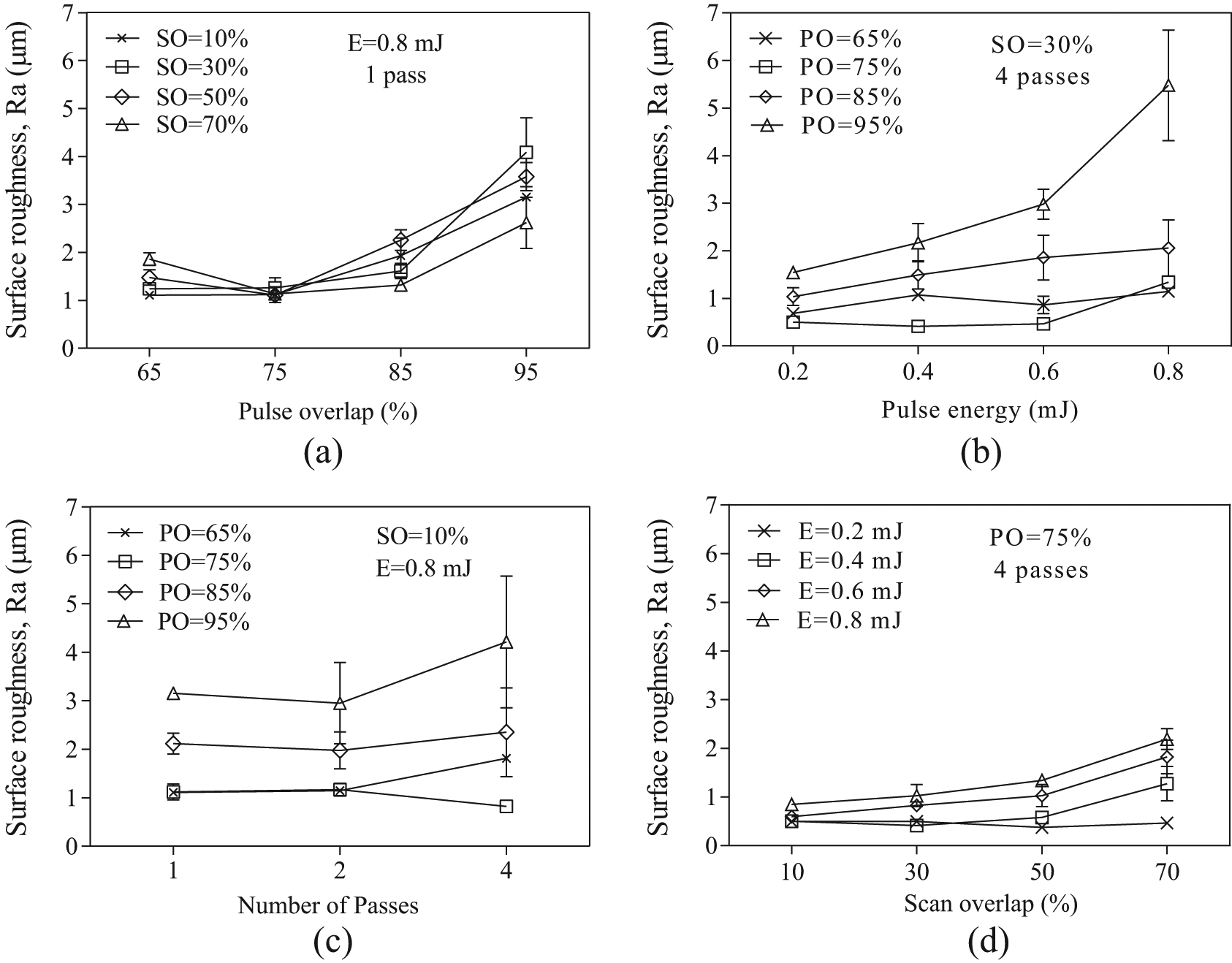
Effect of milling parameters on the surface roughness (the scatter bars show the standard deviation).
It can be noted from Figure 9(a) that the surface roughness appears to decrease initially and then increase with an increase in pulse overlap. This may be attributed to the thermal energy needed to remove different elements of the specimen material. The initial increase in pulse overlap allows the heating time on the local area to increase and remove the edge of protruding diamond grains, smoothening the surface. As the pulse overlap further increases, a large amount of heat may accumulate on the target surface layer, which results in the mass oxidation and loss of diamond grains, as shown in Figure 4(c), thus increasing the irregularity and the roughness of the surface.
As shown in Figure 9(b), an increase in pulse energy results in an increase in surface roughness. This may be explained by the fact that increasing the pulse energy allows a higher laser peak intensity and more material removal for a single pulse, which increases the surface roughness due to the Gaussian distribution of laser energy over the PCD target, as discussed in section “Surface evaporation.” From Figure 9(b), surface roughness is again affected by pulse overlap in the way shown in Figure 9(a), as discussed above.
The effect of the number of passes on surface roughness is shown in Figure 9(c). In general, an increase in the number of passes increases the surface roughness, although in some cases such an effect is not significant. It may be anticipated that a machining operation performed on an already machined and roughened surface will increase the scattering of the laser light and result in a rougher surface in the following passes. This is particularly so when higher pulse overlaps are used (such as 85% and 95%), in which case more material is removed in each pass and the surface generated is rougher. However, when the pulse overlap is small (e.g. 75%), the initial surface roughness generated in previous pass is small, as shown in Figure 9(a), which suppresses the laser light scattering in the following passes and surface roughness may be improved.
Surface roughness shows a generally increasing trend with respect to laser scan overlap, as shown in Figure 9(d). An increase in scan overlap increases the heating time or energy input and hence increases the material removal as well as the formation of periodic structure on the material surface that increases the surface roughness. It is further noted that the increasing trend is negligible under the low pulse energy of 0.2 mJ. This is attributed to the fact that this laser fluence was below the ablation threshold for PCD, so that very little or no material removal took place from the target, and the change to surface roughness was very small.
Characterization of thermally affected subsurface layers
Transformation of diamond to non-diamond carbon in the subsurface layers is a critical defect in the machining process for PCDs, which affects the overall workpiece integrity and the quality of final products such as a cutting tool. Thus, the characterization of subsurface layers and the associated influencing process parameters were investigated experimentally based on an orthogonal experimental design. The experimental study involved three levels of pulse overlap (75%, 85% and 95%), scan overlap (10%, 30% and 50%) and the number of passes (1, 2 and 4), which yielded nine combinations (L9), each of which was tested at four levels of pulse energy (0.2, 0.4, 0.6 and 0.8 mJ), resulting in 36 experimental runs. Additional 12 experiments using some typical milling conditions from Table 2 were also conducted to provide more as-measured data for analysis.
Measurement of non-diamond carbon layer depth
To examine the subsurface layer characteristics after laser irradiation, the milled samples were sectioned (cutoff) in the direction perpendicular to the laser traverse motion, and the cross sections were polished to reveal the characteristics of the cross-sectional surface. Figure 10(a) shows such a polished surface, where any damage induced by the sectioning (or cutting) process has been removed (or minimized) by the polishing process. Figure 10(b) shows a magnified cross-sectional view of a laser-milled surface, which reveals the presence of carbon phase transformation in the form of a darkened layer.
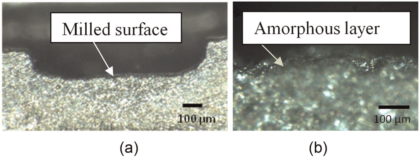
Micrographs of a cross-sectional surface: (a) 500× magnified view of a laser-milled sample and (b) 1000× magnified view of amorphous carbon formation.
To determine the thickness of damaged layer, the measurement on the subsurface layer started from the position on the cross-sectional surface where non-diamond carbon phase was detected and then moved downward by 2–5 µm spacing vertically (varying according to the degree of thickness of damage) until diamond phase was detected. Thus, the thickness of damaged layer could be determined. The measurement of the damaged layer thickness at 10 locations uniformly distributed along the pocket width for each specimen was conducted using the Raman spectroscopy technique, as shown in Figure 11, and the average value was used as the damaged layer thickness.
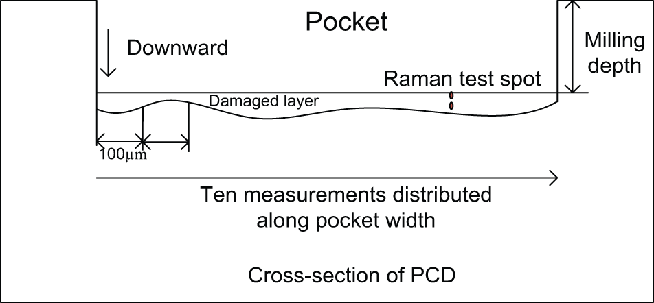
Schematic description of subsurface damage measurements.
Figure 12 shows a typical Raman spectrum collected from a milled subsurface layer, which exhibits two intense bands centered at 1332 cm−1 (varying between 1330 and 1366 cm−1 for other samples) and 1589 cm−1 (varying between 1580 and 1593 cm−1 for other samples) corresponding to a diamond structure and an sp3-hybridized amorphous carbon, respectively. 35 Raman spectra obtained at the positions of a sufficient distance from the specimen surface present a single peak around 1332 cm−1, corresponding to a crystalline diamond structure only.32,33 The thickness of transformed surface layers with respect to the process parameters is analyzed in the following.
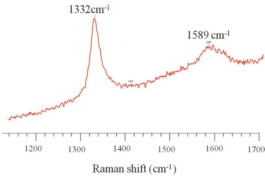
Typical Raman spectrum of a non-diamond carbon layer.
Effect of process parameters on the damaged layer thickness
In this study, the amorphous carbon layer in the subsurface of the specimens is considered as damaged layer. The variation of the damaged layer thickness (Da) with respect to the process parameters is shown in Figure 13. It can be seen from Figure 13(a) that pulse overlap has a significant effect on the formation of amorphous carbon. This has been confirmed by an ANOVA, which gave a significance value of 0.001 for pulse overlap. It can further be noted that the amorphous carbon layer thickness increases initially and then decreases with an increase in pulse overlap. This may be due to the fact that once the heat absorption rate of laser energy by the workpiece exceeds the vaporization rate due to lower traverse speed (or higher pulse overlap), the absorbed energy heats the target material and causes the diamond underneath the surface to transform to amorphous carbon at the elevated temperature. As the pulse overlap is increased, more heat is input into a given area of the target surface and the damaged layer thickness increases. With a further increase of the pulse overlap from 85% to 95%, the pocket produced with a 95% pulse overlap is much deeper than the pocket produced with a smaller pulse overlap when other process parameters remain the same. It is believed that the thermal gradient in the depth direction is higher due to fast heat input and causes graphitization deeper into the diamond subsurface. Thus, more transformed graphite was removed by laser and less amorphous carbon left in the material.
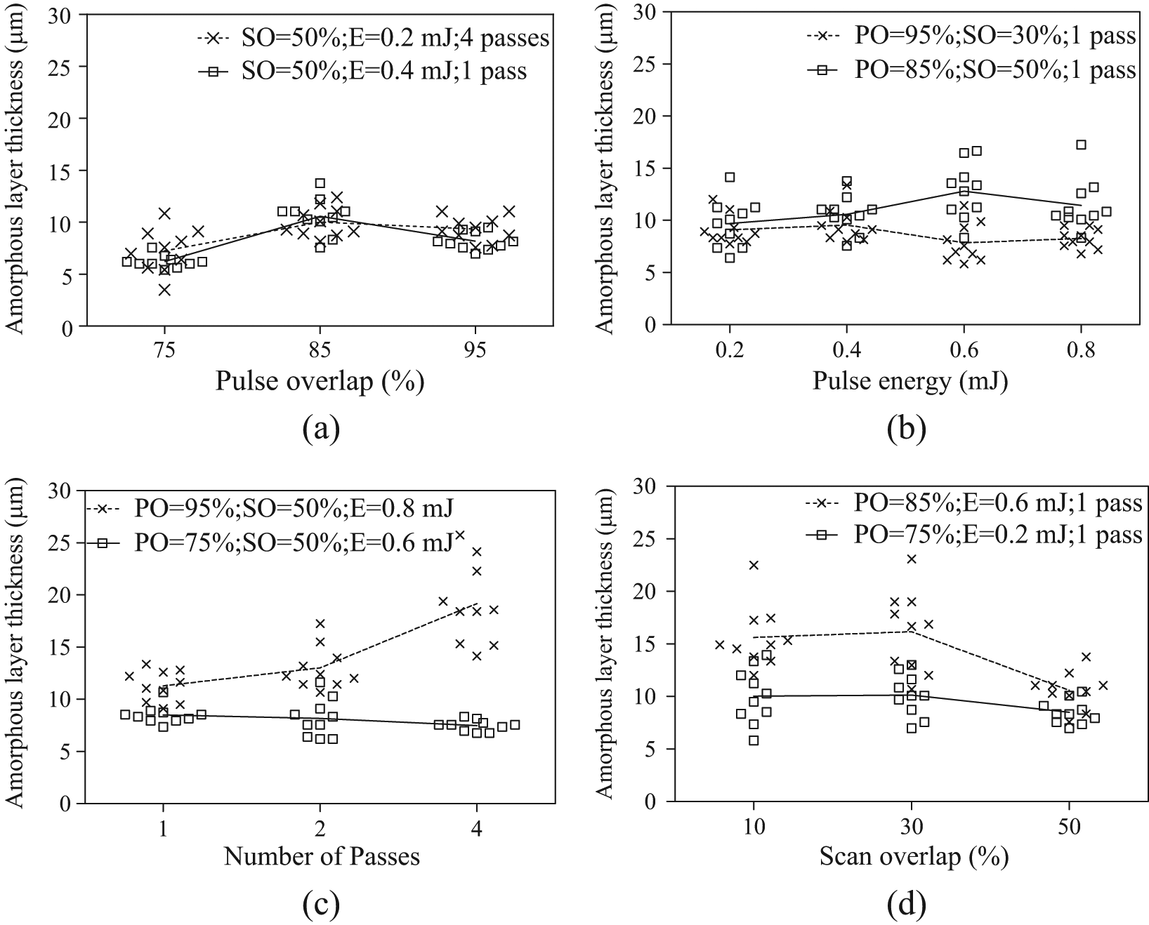
Effect of milling parameters on the amorphous layer thickness (symbols shows experimental data and lines shows the average of 10 measurements). E: pulse energy; PO: pulse overlap; SO: scan overlap.
Figure 13(b) shows the typical trends of the amorphous layer thickness with respect to laser pulse energy found from this study, where the pulse energy does not show a significant effect on the thickness of amorphous layer. This has been confirmed by a statistical analysis (ANOVA) in which the significance value is 0.199 and pulse energy is thus not considered as a significant variable in affecting the amorphous layer thickness. It is believed that since a higher pulse energy causes more material removal, more energy is carried away from the workpiece by the thermal vaporization process, so that the unremoved material is under almost the same temperature contour and the amorphous layer thickness remains almost unchanged with pulse energy.
A statistical analysis shows that the number of passes has a zero significance value, which is the smallest for all the process variables considered, and therefore has the greatest impact on the carbon phase transformation in the subsurface layers. It can be seen from Figure 13(c) that the maximum thickness of the amorphous carbon layer is 22.31 µm under four-pass milling. In a multi-pass milling of PCD, the carbon underneath is isolated from the air that does not oxidize at elevated temperatures. Thus, the energy conducted into the substance in the preceding pass or passes heats the diamond and converts it into graphitic carbon, so that the material ablated in the subsequent pass may contain the transformed graphitic carbon that has a higher heat capacity and lower heat conductivity than the diamond; therefore, more heat is accumulated on the upper layer of the substance than that conducted into the material. Consequently, an increase in the milling passes leads to more carbon phase transformation. It has been found that there is a slight decrease in the amorphous layer formation with the milling passes under the laser pulse overlap of 75%. It may be due to the fact that the absorbed heat used for material ablation and amorphization is in thermal equilibrium or quasi-equilibrium, and no more carbon phase transformation occurred in the following passes.
A statistical analysis shows that scan overlap has a significance value of 0.033, and thus, it has a less effect on the amorphous layer formation than pulse overlap and the number of passes, but more significant than pulse energy. From Figure 13(d), it can be seen that the thickness of amorphous carbon layer generally decreases with an increase in scan overlap. It is believed that as the scan overlap is increased, the transformation of carbon occurred in the previous laser traverse motion is removed from the overlapping area, and thus, more material is removed and less amorphous carbon is left in the remaining material.
Parameter selection consideration
In order to evaluate the overall performance of the laser milling process for PCD, the above analyses of the effect of process parameters on MRR, surface roughness and damaged layer thickness are summarized in Table 3, where the arrowheads indicate the increasing and decreasing trends of the quantities with an increase in each of the four variables.
Milling performance with regard to the process parameters.
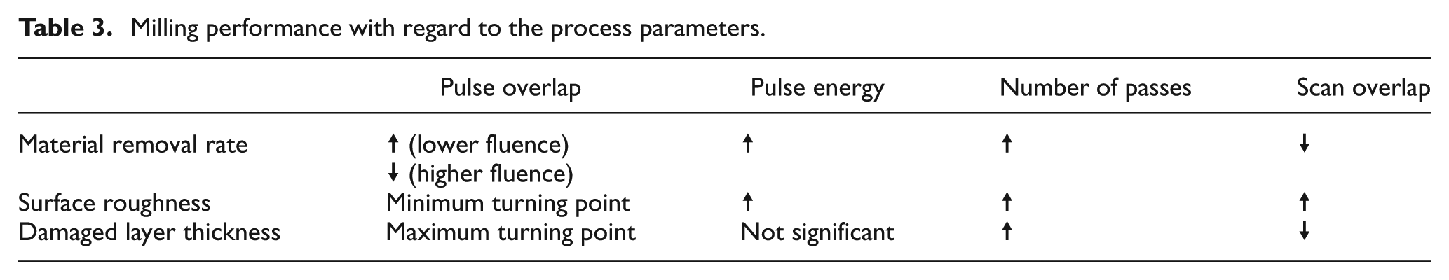
It has been shown that an increase in the pulse overlap results in a decrease in MRR when the pulse energy is in the higher region of the tested range, while there is a general increase in MRR as the pulse overlap increases at the lower pulse energies tested. Meanwhile, surface roughness shows a minimum turning point and the damaged layer thickness has a maximum turning point as the pulse overlap varies. Thus, from the data of this study, pulse overlap of 75% (or 65%) could be used to give a high MRR while achieving the surface roughness and damaged layer thickness at close to their respective optimum. Meanwhile, pulse energy should be selected at the upper region of the tested range, that is, at around 0.8 mJ, for a high MRR without significantly compromising the surface quality. As an increase in the number of milling passes increases all the three quantities, a single-pass milling process should be considered if it could achieve the required depth of milling. It has been shown that while MRR shows a decreasing trend with an increase in scan overlap, the magnitude of decrease is small, particularly in single-pass milling. Likewise, an increase in scan overlap does not result in a significant increase in surface roughness until the scan overlap is increased to beyond 50%. By contrast, when the scan overlap changes over the range tested, there is little change in damaged layer thickness at the lower pulse energies considered; at higher pulse energies, the amorphous layer thickness decreases significantly when the scan overlap increases from 10% to 50%. Thus, a high scan overlap within the range studied, that is, 50%, is recommended.
Conclusion
A study of nanosecond pulsed laser milling of PCD has been presented. It has been shown that the heat distribution and thermal gradient due to the multi-phases of the PCD material play an important role in the formation of surface characteristics. The morphological observations show that the milled surface is formed through some or all of the graphitization, surface evaporation, liquid-phase expulsion and thermomechanical ablation processes. Under the lower laser pulse energy and pulse overlap, the material is mostly ablated along the grain boundaries where the absorptivity is enhanced due to the initial impurities and defects of the target material, and the graphitization is essential for the material removal in this condition. When the laser fluence reaches the ablation threshold value, periodic structural patterns appear on the milled surfaces as a result of inhomogeneous absorption and reflection of the laser energy induced by Gaussian profile of the laser beam and surface topography, so that the surface evaporation is the dominant material removal mechanism. The ablation is mostly associated with the crack formation as a result of the lattice strain induced by the defect along the grain boundaries and thermal gradient between the multi-phases. Fracture is more likely to be formed under the higher laser pulse energy and higher pulse overlap considered because of surface tension induced by the melting and ablation of cobalt. The thermomechanical ablation takes place because of the propagation of graphitization into the deeper layer and the loss of bonding for diamond grains as a result of the cobalt melting and removal.
The experimental results show that laser milling is a viable and effective technology for the micromachining of PCDs at relatively high MRR, relatively good surface finish and small thermal damaged layer by appropriately selecting the process parameters. The analysis of the laser-milled surfaces has shown that laser pulse energy should exceed the ablation threshold in a single-pass milling for material removal. The milled surface morphology and Raman spectrum analysis have indicated that surface graphitization appears to be inevitable for material ablation under laser irradiation. Plausible trends for the effect of process parameters on the MRR, surface roughness and subsurface damage have been amply discussed. In general, MRR increases with an increase in pulse energy and the number of milling passes, but increases with pulse overlap at lower laser fluence and decreases at higher laser fluence. Furthermore, MRR decreases only marginally with an increase in scan overlap. Surface roughness increases with an increase in pulse energy, the number of milling passes and scan overlap. By contrast, surface roughness has a minimum turning point as the pulse overlap is increased. The amorphous layer thickness formed increases with the number of milling passes, decreases with an increase in scan overlap and does not vary significantly with pulse energy; there is a maximum turning point for the amorphous layer thickness when pulse overlap changes. Based on the analysis, a recommendation has been made on the selection of the process variables at 75% (or 65%) pulse overlap, 0.8 mJ pulse energy and 50% scan overlap under a single-pass operation if it can meet the process requirement for the depth of cut; otherwise, multi-pass milling may be considered and further improvement in surface quality will rely on subsequent finishing processes.
Footnotes
Appendix 1
Declaration of conflicting interests
The authors declare that there is no conflict of interest.
Funding
This research received no specific grant from any funding agency in the public, commercial or not-for-profit sectors.