
Abstract
This work studies the effect of filler metal on the mechanical and microstructure properties of dissimilar aluminium alloys of 5083-O and 6061-T6 welded using metal inert gas welding. The metal inert gas welding was used because it is widely being used for joining aluminium alloys for aerospace, marine, automotive and many other application of commercial importance. The joints were fabricated using filler metals ER4043 and ER5356. Both welded samples were cut according to ASTM B-557M to obtain the tensile strength, and Vickers hardness was measured at welded metal, heat-affected zone and base metal. The mechanical properties of welded samples were analysed by using micrographs obtained from optical microscopy. From the results, the filler metals ER5356 were more able to enhance the mechanical properties and microstructure characteristics of the welded samples.
Introduction
Magnesium-based aluminium alloys (Al–Mg alloy) are non-heat treatable alloys with medium strength, high ductility, excellent corrosion resistance and weldability. Wrought Al–Mg alloys are used as structural materials in marine, automotive, aircraft and cryogenic applications. These materials exhibit their strength mainly from solid solution strengthening by Mg, which has a substantial solid solubility in aluminium. 1 Al–Mg–Si alloy, one of the widely used heat-treatable alloys, is choice for medium-to-high-strength requirements and has good toughness characteristics. The major alloying elements magnesium (Mg) and silicon (Si) increase the strength of the alloy through precipitation hardening. These types of alloys are also age hardenable and usually heat-treated to T4 (natural ageing) and T6 (artificially ageing) temper conditions to develop required strength. Al–Mg–Si alloys are widely used in transportation components, machinery equipments, recreational products and consumer durables. 2
For aluminium alloy, the most common joining method is fusion welding. Generally, 5xxx and 6xxx alloys are easily welded by conventional arc welding processes, metal inert gas (MIG) welding and tungsten inert gas (TIG) welding. 3 However, some important characteristics, such as solidification cracking, porosity, heat-affected zone (HAZ) degradation and so on must be considered during welding, due to the greater amount of alloying elements used in commercial alloys. 4 Solidification cracking is intergranular, that is, along the grain boundaries of the weld metal, and it occurs during the terminal stage of solidification, when the tensile stresses developed across the adjacent grains exceed the strength of the completely solidified weld metal. The solidifying weld metal tends to contract because of both solidification shrinkage and thermal contraction. The surrounding base metal also tends to contract, but not as much, because it is neither melted nor heated as much the weld metal. Therefore, the contraction of the solidifying metal can be hindered by the base metal results in solidification cracking. It is found that fine equiaxed grains are often less susceptible to solidification cracking than coarse columnar grains. If the copper (Cu) content of weld metal is raised sufficiently, solidification cracking can be significantly reduced. Minor alloying elements (Fe, Si, etc.) have also been found to reduce the solidification cracking susceptibility of aluminium alloys. 5 Severe liquation or hot cracking can occur in the HAZ during welding. The tendency of hot cracking depends on the chemical composition of the alloy. The alloys of the 6xxx series alloys are, for instance, more sensitive to hot cracking than the alloys of the 5xxx series. Porosity forms when hydrogen gas is entrapped during solidification as it is highly soluble in molten aluminium. Hydrogen gas solubility in the solid is less than in liquefied phase of aluminium, so hydrogen is rejected from solid to melted material, causing localized super saturation, bubble nucleation and growth. 6 Increase in porosity is generally associated with high humidity and poor surface preparation. Use of suitable inert gases to shield the weld pool can reduce porosity. 7
The welding parameters and type of filler metal strongly affect the mechanical properties of weldment. A study of the mechanical properties of welded plates of commercial 6061-T6 aluminium alloy with a thickness of 12.7 mm was made by Ambriz et al. 8 In this study, a filler wire ER 40433 of diameter 1.2 mm was employed to fabricate the single V-groove joint at current 210 A and voltage 23 V. The effect of the welding profile generated by the modified indirect electric arc technique on the fatigue behaviour of 6061-T6 aluminium alloy of thickness 9.5 mm was investigated using ER 4043 filler wire of 1.2 mm diameter, 230 A current and 24 V voltage by Ambriz et al. 9 in another work. An investigation by Ahmad and Bakar 10 was done on gas metal arc welded 6061 aluminium alloys with a thickness of 10 mm to investigate the effect of post-weld heat treatment on the mechanical and microstructure properties. The filler used for the welding process was ER 4043 with a diameter of 1.2 mm, and welding current of 210 A, voltage of 24 V, air flow of 23.6 L/min and travel speed of 3.6 mm/s were used for fabrication of the joints in this work. Kuk et al. 7 investigated the effects of temperature and shielding gas mixture on fatigue life of 5083 aluminium alloy of thickness 12 mm welded by Al5183-WY welding wire of 1.2 mm diameter at 220 A current, 21 V, 23 V, 26 V and 29 V voltage with 30–50 cm/min speed. The literatures7–17 suggest that filler metal ER4043 is more appropriate for welding of 6xxx aluminium alloys and filler metal ER5356 is more appropriate for 5xxx aluminium alloys.
Arc welding of aluminium alloys of different composition (dissimilar alloys) gives problem due to difference in thermal conductivity. The heat produced by the arc will flow easily in the material with the large thermal conductivity. This can result in lack of fusion of this material or excessive melting of the material with the lower thermal conductivity. There are only few works available on fusion welding of dissimilar aluminium alloys. Luijendijk 11 investigated the welding performance, hot tearing tendency and mechanical properties of gas tungsten arc (GTA) welded dissimilar aluminium alloys of the series 5xxx (Al–Mg) and 6xxx (Al–Mg–Si). Four material combinations, AA5083 O–AA5754 H32, AA5083 O–AA6060 T6, AA5083 O–AA6061 T6 and AA6082 T6–AA6060 T6, were examined to the asymmetry of the weld and melting behaviour of the different weld grooves. The weld materials used in the welding of the four material combinations were ER5356, ER5356 and ER4043, ER5356 and ER4043, ER5356 and ER4043, respectively. The technique to realize a good weld for a combination of 5xxx and 6xxx materials were analysed in respect of groove melting and weld penetration. Mechanical properties of the welds for the different material thickness were also investigated. The proper selection of filler material for dissimilar aluminium alloys joint is essential for the strong weldments. In this work, the effect of two filler materials, ER 4043 and ER 5356 on the microstructure and mechanical properties of MIG-welded dissimilar aluminium alloys (5083-O and 6061-T6 combination) was examined, and an attempt is made to explain the static mechanical properties of the joint in context of microstructure.
Experimental work
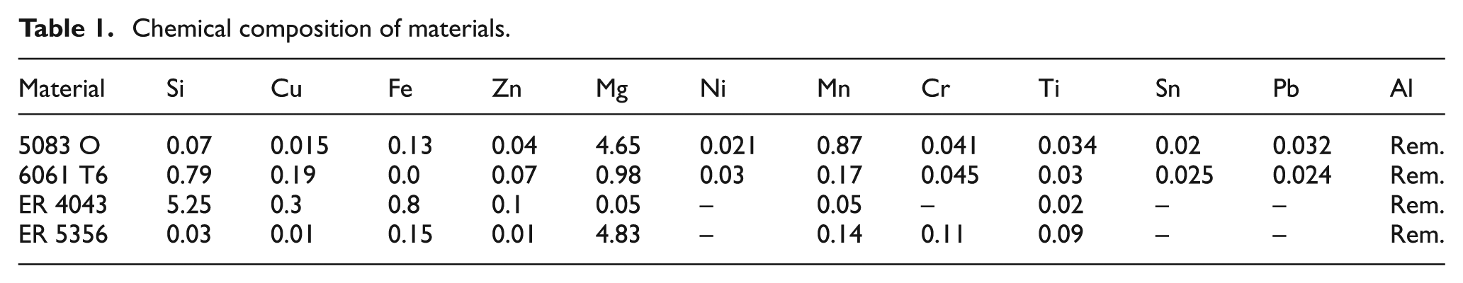
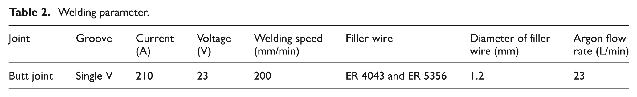
The plates of aluminium alloys (5083-O and 6061-T6) were cut into the required sizes (300 × 150 × 8 mm3) by cutting and grinding with a power hacksaw. Single ‘V’ butt joint configuration was prepared to MIG-welded joints of dissimilar alloys as shown in Figure 1(a). Single-pass welding procedure was applied to make the joints. Two types of samples were fabricated: one using ER 4043 filler wire and another using ER 5356 filler wire. High-purity argon gas was used as shielding gas. The chemical composition of base metals and filler metals are presented in Table 1. The welding conditions and process parameters presented in Table 2 were used to make the joints. The welding torch was kept above the edge of 6061-T6 plate for better weldments during welding as the thermal conductivity of 6061-T6 alloy is more than 5083-O alloy.
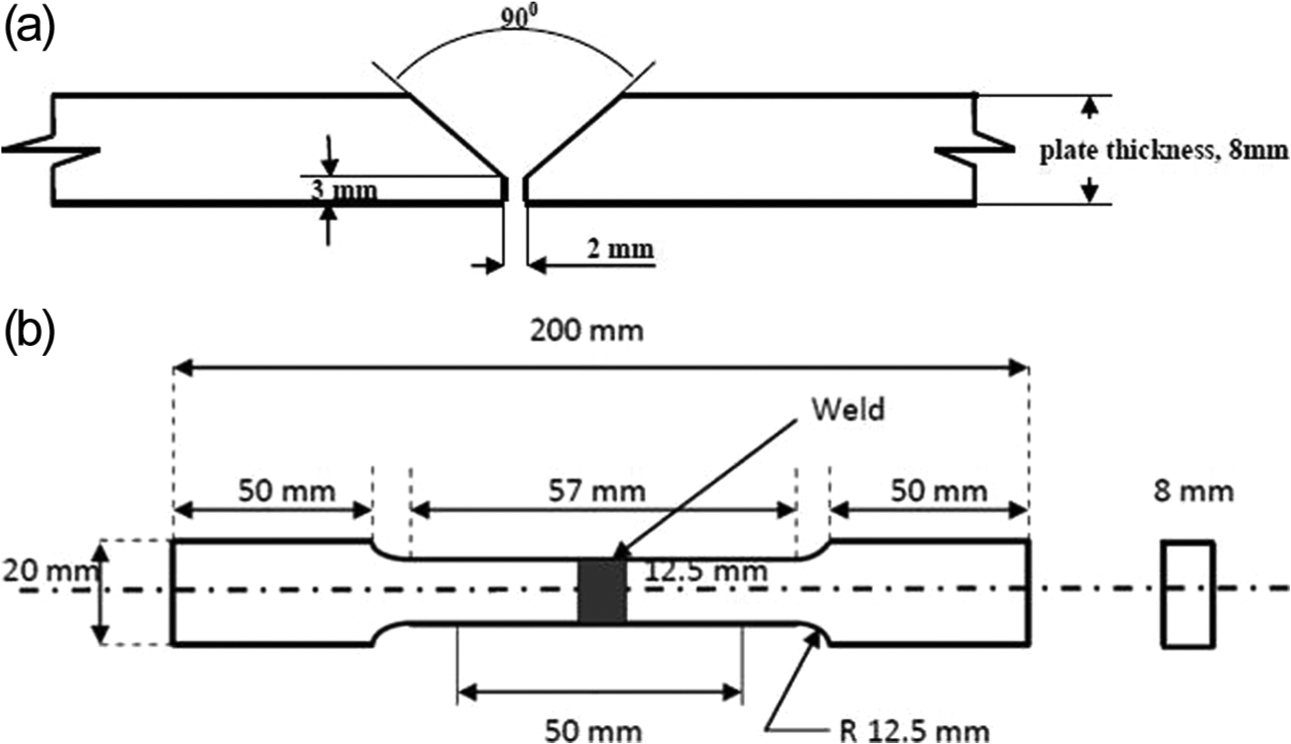
(a) Welded plate showing single V-groove joint and (b) transverse tensile specimen.
Chemical composition of materials.
Welding parameter.
Tensile specimens were prepared to obtain ultimate tensile strength and percentage of elongation (fracture strain). Procedures prescribed by the ASTM B-557M standard were followed for the preparation of the transverse tensile specimens. 19 The specimens are machined perfectly into the specified dimensions, as shown in Figure 1(b), by a computer numerical control (CNC) milling machine. Vickers hardness testing machine was used for measuring the hardness of the weld metal, HAZ side I and HAZ side II (at the top, middle and bottom sections) and base metals according to procedures prescribed by the ASTM E92 standard. The weld metal, HAZ (side I and side II) and base metals are shown in schematic diagram in Figure 2. Microstructural examination was carried out at weld metal, HAZ side I and HAZ side II using an optical microscope with polished surface using standard metallographic techniques and etched with Keller’s reagent. Microstructure of fractured surface in both samples was also examined.
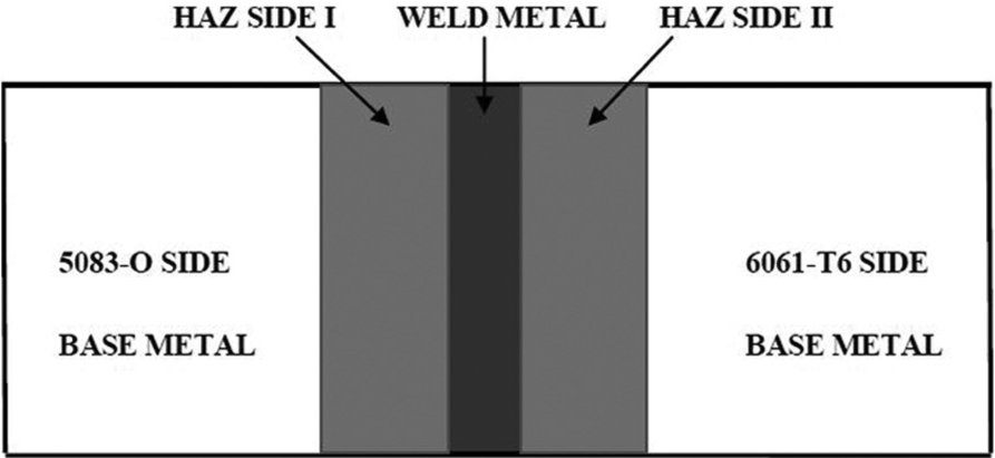
Schematic diagram of welded plate.
Results and discussion
Tensile strength and hardness
The tension tests were performed on FIE make Universal Testing Machine (UTE-60), and it was observed that the both samples, sample 1 (welded using ER 4043 filler wire) and sample 2 (welded using ER 5356 filler wire), were fractured in weld metal region. The specimen of both samples is shown in Figure 3. The tensile strength and the percentage of elongation were evaluated based on the average of three values as presented in Figure 4. The load–displacement diagrams of a specimen of both samples are shown in the Figure 5. The average tensile strength of samples 1 and 2 were 112 and 144 MPa, respectively. Thus, a 28.5% increment was achieved when implementing ER 5356 filler wire. An increase in tensile strength was also observed in the literatures due to the strongly modified microstructure. Generally, fine equiaxed grains tend to improve mechanical properties of welded joint by reducing solidification cracking. According to Hall–Petch equation, σ0 = σi+ kd(−1/2) (where σ0 is the tensile stress, σi is friction stress, k is a constant and d is the mean grain diameter), tensile stress of metallic materials varies inversely proportion to the grain size. The comparative discussion is presented on the basis of micrographs in section ‘Microstructure’.
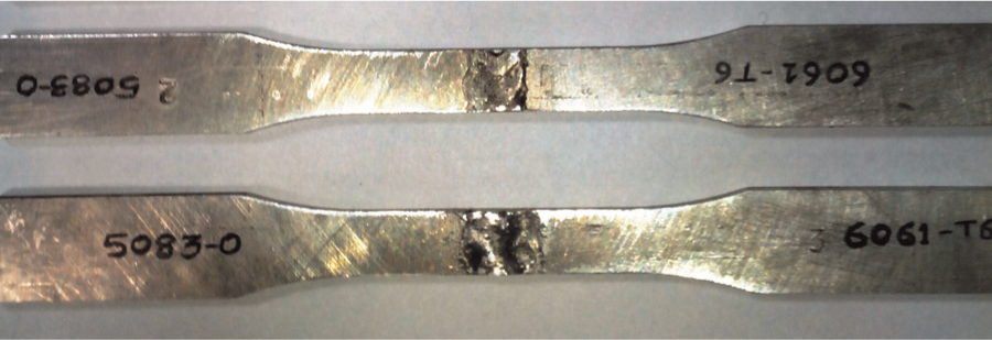
Photograph of specimen 1 and specimen 2.
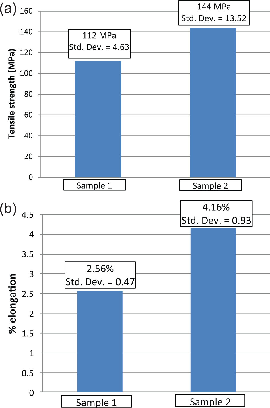
Bar chart of (a) tensile strength (b) %elongation of sample 1 and sample 2.
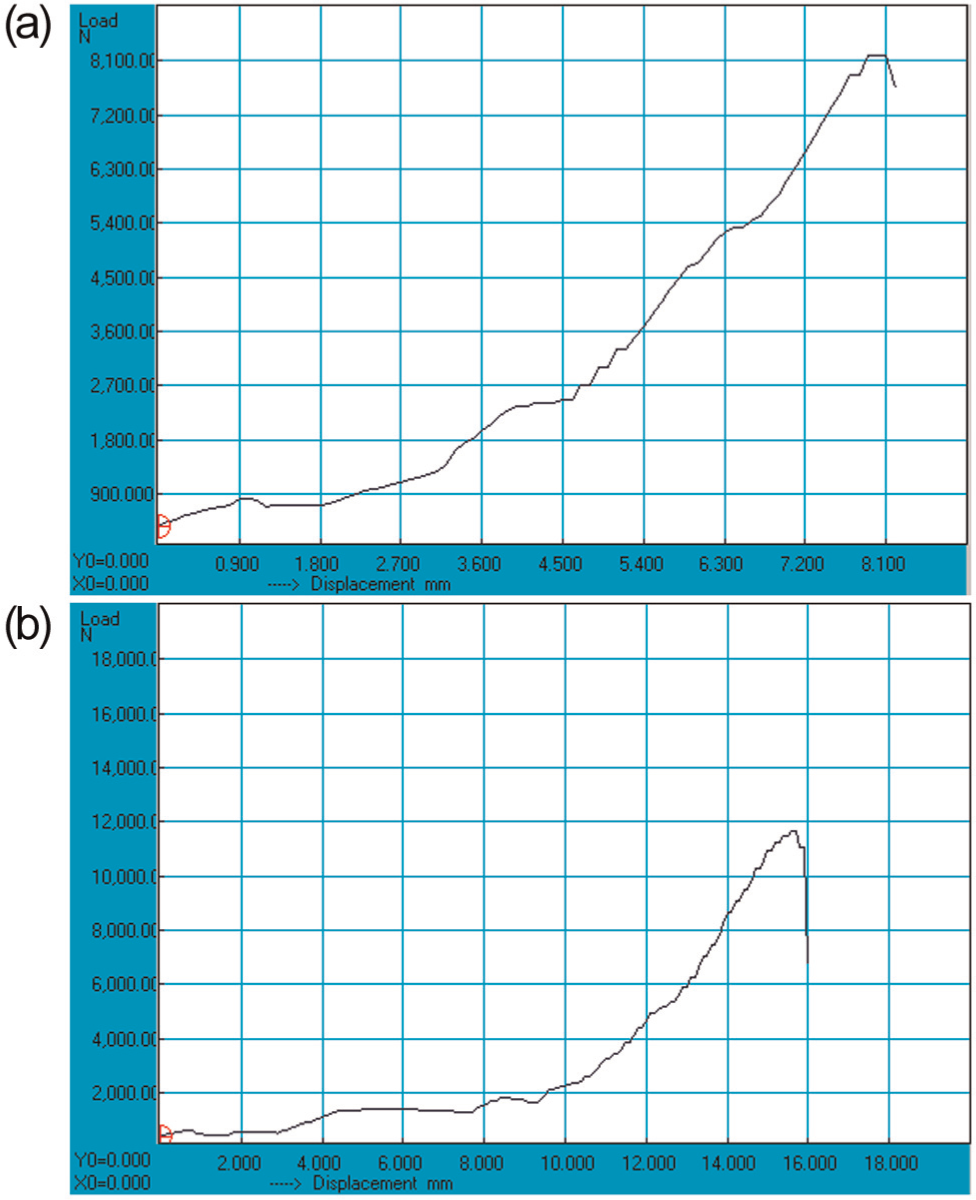
Load–displacement diagram of (a) a specimen of sample 1 and (b) a specimen of sample 2.
The percentage of elongation was calculated from load–displacement diagram, and an average value was evaluated based on three values. The percentage of elongation for samples 1 and 2 were 2.56% and 4.16%, respectively. The elongation was calculated from the gauge length of this tensile specimen, and it contains several parts of materials, including two different base metals and two HAZs, weld metal. Each part contributes its deformation to the total elongation value of the specimen. Hence, the reported elongation is the elongation of whole specimen, and it is used only for comparison of ductility of samples. The use of ER 5356 filler wire in fabricating the joints increased the percentage of elongation of specimen by 62.5%.
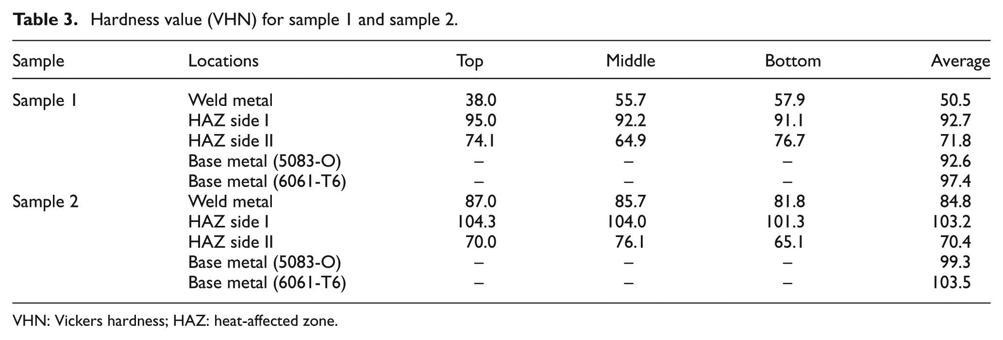
A Vickers hardness test was performed at three different locations, at the top, middle and bottom, of weld metals, HAZ side I and HAZ side II. The average hardness values for sample 1 (welded using ER 4043 filler wire) and sample 2 (welded using ER 5356 filler wire) are shown in the Table 3. Figures 6 and 7 show the hardness value of weld metal, HAZ side I and HAZ side II at top, middle and bottom of samples 1 and 2, respectively. A huge increment of 67.9% in hardness of weld metal was observed when implementing ER5356 filler wire. Similarly, 11.3%, 7.2% and 6.2% increments were achieved in hardness of HAZ side I, base metal 5083-O and base metal 6061-T6, respectively, when using ER5356 filler wire. The refined microstructure is responsible for the increase in hardness.
Hardness value (VHN) for sample 1 and sample 2.
VHN: Vickers hardness; HAZ: heat-affected zone.
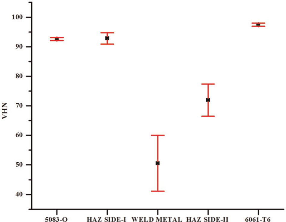
Hardness variation of weld metal, HAZ side I and HAZ side II for sample 1.
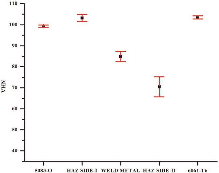
Hardness variation of weld metal, HAZ side I and HAZ side II for sample 2.
Microstructure
Microstructure of joints was examined at weld metal region and HAZ. From the micrographs, it is understood that there is an appreciable difference in grain size of weld metal regions and HAZ of both samples. Figure 8 shows the micrographs for sample 1. In micrograph of HAZ side I (Figure 8(a)), which constitutes base metal on right and weld metal on left. It reveals that dendrites of solid solution are less equiaxed at weld metal; however, the fusion of weld to base metal (5083-O) is adequate. In micrograph of weld metal (Figure 8(b)), as cast, annealed type weld show interdendritic particles of eutectic silicon and the light etching matrix of aluminium solid solution. The microstructure of HAZ side II (Figure 8(c)) includes base metal on left and weld metal on right. The weld-base metal transition show adequate fusion containing particles of Mg2Si (black) structure.
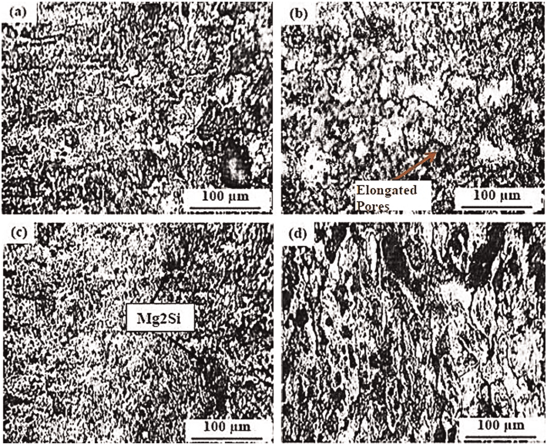
Optical micrographs of (a) HAZ side I, (b) weld metal region, (c) HAZ side II and (d) fractured surface of joint welded by ER4043 filler metal.
Figure 9(a) shows the micrographs of HAZ side I of sample 2 constituting base metal, 5083-O (right) and weld metal (left). In the micrograph, Al–Si eutectic is present between the dendrites of weld bead and AlMg2Si was present between the grains of the HAZ. Fusion of weld to base metal is adequate, and there was no any evidence of porosity. In the micrograph of weld metal, shown in Figure 9(b), as cast, self-annealed and crystalline structure shows particles of eutectic solution in an aluminium matrix. Figure 9(c) shows the micrographs of HAZ side II. The structure at edge of the HAZ shows adequate fusion of weld to base metal. Al–Si eutectic is present between the dendrites of the weld bead. In micrograph, a localized porosity (large black area) is evident; it is perhaps due to improper cleaning of the sample.
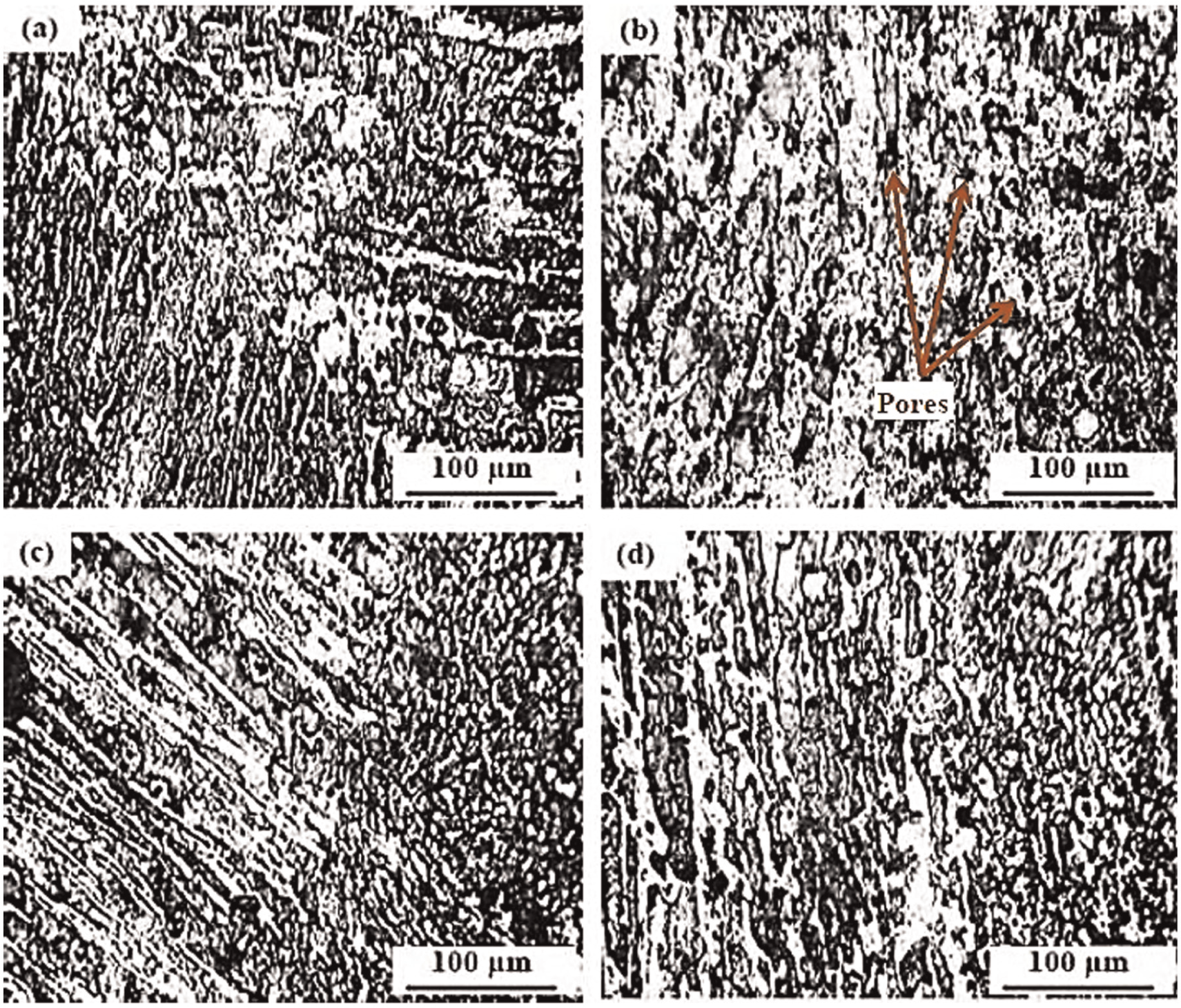
Optical micrographs of (a) HAZ side I, (b) weld metal region, (c) HAZ side II and (d) fractured surface of joint welded by ER5356 filler metal.
The microstructure revealed response of the dissimilar aluminium joint to filler metals. The revealed structure in Figure 9 shows a more dispersed precipitate of Mg2Si intermetallic compound in Al-matrix. A well-dispersed precipitate of the Mg2Si intermetallic compound was responsible for the improved properties of the sample 2. Fine equiaxed grains were observed for sample 2. Fine equiaxed grains are capable to accommodate contraction strains more easily, that is, it is more ductile than columnar grains, and it may result in enhanced tensile strength of sample 2. Also, the grain boundary area is much greater in fine-grained material and therefore harmful low melting point segregates are less concentrated at grain boundary, resulting in enhanced mechanical properties. 12 Hardness in the fusion zone is the lowest due to the as-cast nature of the microstructure, which is characterized by coarse dendritic grains and interdendritic segregates. Hardness is higher in sample 2 as compared to sample 1, and this could be due to the refined microstructure and low segregation of strengthening phases. Microstructures revel less and dispersed porosity in sample 2. It is desirable to limit porosity defects in aluminium weldments. Columnar grains tend to produce an elongated porosity, whereas the equiaxed grains tend to form a smaller and more dispersed porosity. 5 According to theory of formation of gas porosity in aluminium alloys, the long pores precipitate at a later stage of solidification, when crystals/dendrites are growing throughout the melt and are influenced by the hydrogen enrichment and the shrinkage pressure in the columnar interdendritic area during solidification. On the other hand, the small and fissured pores precipitate at a very late stage of solidification, the bubble growth is severely limited and the shape is determined by the interdendritic space available. Therefore, the large amounts of equiaxed grains solidified in the weldments tend to form the small and dispersed porosity. 18
Conclusion
Based on this investigation, the following conclusion can be made:
The welding of dissimilar aluminium alloy, 5083-O and 6061-T6, is very difficult due to different thermal conductivity. Excessive melting in alloy with lower thermal conductivity and lack of fusion in alloy with greater thermal conductivity are observed. The selection of proper position of welding torch is very important parameter for the strong weldments for dissimilar aluminium alloys. In this work, good weldments are achieved by placing the torch above the edge of 6061-T6 alloy plate.
Filler metal ER5356 is more appropriate for the welding of alloy combination 5083-O and 6061-T6. A 28.5% increment in tensile strength can be achieved by ER5356 in comparison to ER4043. A huge increment of 67.9% in weld metal hardness is observed by ER5356 filler wire.
Similarly, 11.3%, 7.2% and 6.2% increment in hardness can be achieved for 5083-O side HAZ, 5088-O base metal and 6061-T6 base metal, respectively, by using ER5356 filler metal. However, no much difference in hardness of 6061-T6 side HAZ is observed.
The microstructure of HAZ side I zone, Weld metal zone and HAZ side II zone made by ER5356 filler metal shows fine equiaxed grains, while columnar grains are found in joints made by ER4043 filler metal. Fine equiaxed grains are more ductile than columnar grains, so it improves mechanical properties, tensile strength, percentage of elongation and hardness.
The microstructure of weld metal zone made by ER5356 filler metal revels less and dispersed porosity, while that made by ER4043 filler metal shows elongated porosity.
Footnotes
Declaration of conflicting interests
The authors declare that there is no conflict of interest.
Funding
This research received no specific grant from any funding agency in the public, commercial or not-for-profit sectors.