
Abstract
The pulsed metal inert gas welding and continuous metal inert gas welding with various parameters are implemented on 2-mm-thick Invar36 alloy plates. The pulsed metal inert gas welding and continuous metal inert gas welding with the same filler metal and base metal are compared by considering the morphology, microstructure of weld seam and mechanical properties. It is indicated that the size of weld seam obtained in pulsed welding is significantly different from that in continuous welding. Meanwhile, it reveals that there is a triangle zone at the bottom of weld seam in both types of welding technology for Invar36 alloy. The microstructure in triangle zone of pulsed welding and continuous welding is focused. In addition, the essential difference between pulsed metal inert gas welding and continuous metal inert gas welding is discussed in detail by analyzing the formation mode of the droplet metal at the end of wire.
Keywords
Introduction
Invar alloy is based on Fe-Ni alloys with a relatively low coefficient of thermal expansion compared to other metal materials. The coefficient of thermal expansion is the lowest when Fe to Ni is 64 to 36 according to the Invar effect.1,2 Furthermore, the coefficient will change with temperature, but it is basically constant below 673 K. 3 Currently, Invar alloy has been applied in precise electronic equipment, liquefied natural gas vessel and aviation die manufacturing owing to the outstanding property. 4
Welding is commonly employed as the primary method to join Invar alloy. Presently, there are a variety of welding methods applied to the connection of Invar alloy, including shielded metal arc welding (SMAW), submerged arc welding (SAW), tungsten inert gas (TIG) arc welding, metal inert gas (MIG) arc welding, friction stir welding (FSW) and laser welding (LW).5–7 Besides, some improved welding methods have been developed, for example, laser–TIG hybrid welding, 8 pulsed MIG and so on.
Li et al. 9 made a comparative investigation between LW and laser–TIG hybrid welding of Invar alloy by analyzing the microstructure, coefficient of thermal expansion and mechanical properties of the welded joints. The research results demonstrated that the grain size of hybrid welding is smaller than that of LW. Moreover, the ultimate tensile strength and yield strength of hybrid welding is significantly higher than that of LW. Zhan et al. 10 studied the multi-layer laser–MIG hybrid welding of 19.05-mm-thick Fe-36Ni Invar alloy plate using the numerical method and experimental method, which drew a quantitative conclusion that the maximum residual stress and distortion of Invar alloy plate after hybrid welding is 300 MPa and 0.4 mm, respectively. Wu et al. 11 investigated the characteristic of pulsed LW for 2-mm-thin Invar alloy, taking the influence of welding parameters on weld seam forming into account. It is found that the laser power and the pulse of laser are the most critical influence factors for the weld penetration and weld width. In addition, the research results show that the microstructure of weld seam basically consists of columnar austenite. A fiber LW procedure was developed to join cemented carbides and carbon steels plate where Invar alloy was as the interlayer. Besides, the optimized welding parameters with rational weld width and penetration were obtained. 12
Xu et al. 13 conducted a dissimilar-metal welding research on cemented carbide and Invar alloy using gas tungsten arc welding. It was revealed that the interface is a composite of micrometer-sized dendrites dispersed in the matrix. Moreover, the round dendrite is a few micrometers in length and the arm spacing of the dendrite is less than 5 μm. The Mo-alloyed invar alloy was prepared and the microstructures, mechanical properties and thermal expansion behavior were studied by Liu et al. 14 In addition, the microstructure of Invar alloy under different aging conditions was investigated in detail. As illuminated in these results, the amount, size, morphology and distribution of the Mo2C secondary phase can be tailored by adjusting aging processes. Qiu et al. 15 fabricated Invar36 samples by the selective laser melting technology at the constant laser power with varying laser scanning speed. They presented a detailed investigation for the obtained microstructure of Invar36 sample.
Köse et al. 16 used the pulsed DC robotic MIG welding method to weld the 5754 aluminum alloy sheets with different welding speed, in which the microstructure and mechanical properties of welded joint were studied. The pulsed MIG welding technology with high deposition rate was adopted on Al-5083 thick plate by Lee et al. 17 The effect of wire size and different parameters on the morphology of joint was discussed in detail. Gao et al. 18 investigated the effect of microstructure and mechanical properties of welded joint of 4N01 alloy by pulsed MIG welding. It was found that the grain in heat affected zone (HAZ) is obviously coarsening. Besides, the strengthening phase obviously precipitates in the boundaries and the joints coefficient of double pulse is higher than that of signal pulse. Song and Wang 19 performed the pulsed MIG welding on AZ31B magnesium alloy. The research results showed that the stable globular transfer is presented during the pulsed MIG welding process with the optimized parameters. Moreover, the ultimate tensile strength of welded joint is 94% of base metal and the average elongation is 11%. Yan et al. 20 established a visual sensing system to monitor the evolution of molten pool in pulsed MIG welding. In addition, the research results about the continuous MIG welding were reported.21–24 Zhang et al. 25 compared the pulsed LW with continuous LW of 1.5-mm-thick 5052 aluminum alloy plate. It can be found that the welded joint of pulsed LW is better than that of continuous LW due to the better control for the porosity in the pulsed LW.
At present, there have been some studies to investigate the pulsed MIG welding process, but the analysis is mostly a brief description of the experimental results. It can be found that there is almost no research result on comparison between pulsed and continuous MIG welding on Invar alloy. However, the pulsed MIG welding presents excellent characteristics comparing with the continuous MIG welding during the welding of Invar alloy. The comparative study with the continuous MIG welding is an effective method for further investigation of the pulsed MIG welding.
In this study, the Invar36 alloy plates were joined using pulsed MIG welding and continuous MIG welding with different welding parameters. The welding effect is comprehensively compared according to the analyzing results on morphology of welded joint, microstructure and mechanical properties. Moreover, the mechanism causing these differences between pulsed MIG welding and continuous MIG welding is discussed in detail.
Experimental details
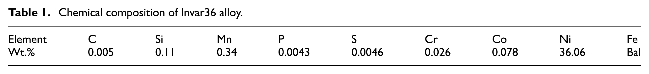
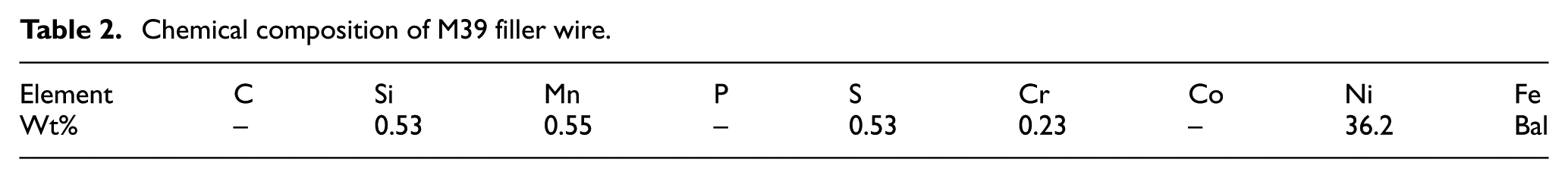
The particular chemical composition of Invar36 alloy is shown in Table 1. Invar alloy thin plate with the dimension of 100 mm × 45 mm × 2 mm is adopted in the experiment. The M39 filler wire with the diameter of 1.2 mm is used as the filler material and the chemical composition of M39 wire is shown in Table 2. To prevent the molten metal from being oxidized, the argon with the purity of 99.99% is used as shielding gas.
Chemical composition of Invar36 alloy.
Chemical composition of M39 filler wire.
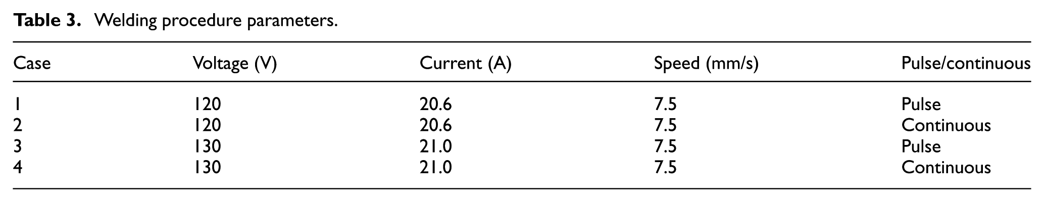
The comparative experiment procedure is based on TAWERS-1400WG3 MIG welding robot system provided by Panasonic Company, which includes the welding robot system, MIG welding power source, transmission device of shielding gas and filler wire feeding mechanism. To achieve excellent welded joints, the cleaning procedure for these plates is necessary before the welding process, including polishing the surface of the Invar alloy plates to remove the rust, as well as scrubbing the surface with acetone to wipe off the grease. A total of four sets of comparative experiments, including two sets of continuous MIG welding experiments and another two sets of pulsed MIG welding procedures are conducted in this study. Welding parameters used in the experiment are shown in Table 3. The default frequency of pulsed current is 15 Hz. In addition, the welding experiment is conducted with 18 L/min shielding gas to protect the weld molten pool. The welding mechanism of pulsed MIG welding and continuous MIG welding is presented in Figure 1.
Welding procedure parameters.
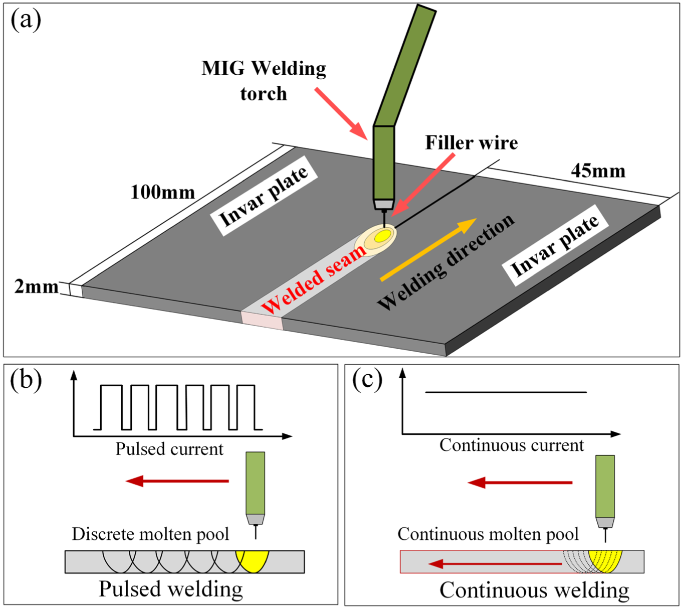
Heating mechanism of pulsed MIG welding and continuous MIG welding: (a) sketch map of MIG welding process, (b) forming process of molten pool in pulsed MIG welding and (c) forming process of molten pool in continuous MIG welding.
Specimens prepared for the microstructure observation are cut out by electric spark cutting machine. The microstructure of the welded joints with four sets of welding parameters is investigated using the optical microscope after polishing and etching for 20 s with the aqua regia, in which the hydrochloric acid to the nitric acid is 3 to 1.
Mechanical properties including the Vickers microhardness and the tensile strength of the welded joints are measured, in which the sample for microhardness test is the same with that for the microstructure observation experiment. The specimen for the tensile strength test is processed into the standard specification using electric spark cutting machine shown in Figure 2. Meanwhile, the welded joint of the tensile specimen is machined so that the section shrinkage in the tensile test can be measured accurately as shown in Figure 2(a). During the microhardness test process with a load of 300 g for 15 s, the interval distance between points is 0.5 mm. Moreover, there are three sets of tensile tests for each case with the drawing speed of 2 mm/s during the tensile test process. In addition, the fracture surface of different welded joints is observed through the scanning electron microscope (SEM).
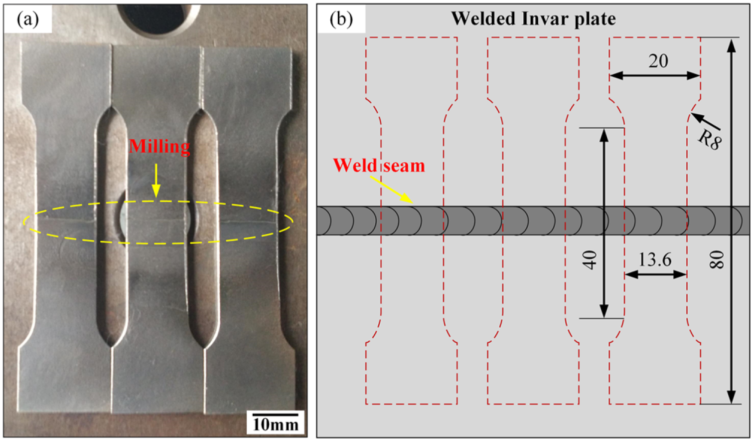
Specimens structure for tensile test: (a) specimens for the tensile test and (b) the size of specimens for the tensile test.
Results
Morphology
The welded joints of Invar alloy plates obtained in continuous MIG welding and pulsed MIG welding are shown in Figures 3 and 4, in which Figure 3 exhibits the front forming of different welded joints. The cross section and the back forming of different welded joints are presented in Figure 4. It can be found that the front weld seam with different parameters is well formed without the obvious welding defect except that there is one pore to be observed in the cross section of case 2 in Figure 3(b). The back forming is obviously different under different welding parameters as shown in Figure 4, in which case 2 emerges the incomplete penetration defect in Figure 4(b). However, the effect of back forming in the other cases is satisfactory.
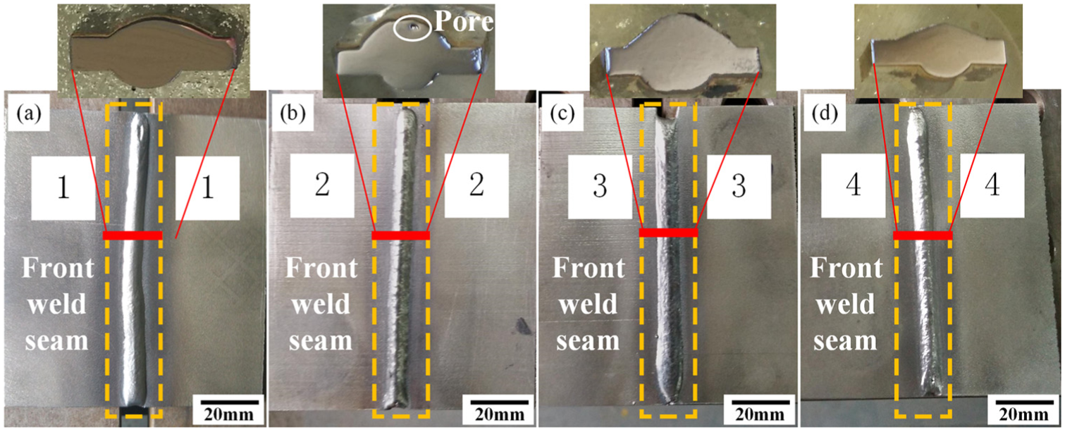
Front morphology and cross section of welded joints with different welding parameters: (a) front morphology and cross section of case 1, (b) front morphology and cross section of case 2, (c) front morphology and cross section of case 3 and (d) front morphology and cross section of case 4.

Back morphology of welded joints with different welding parameters: (a) back morphology of case 1, (b) back morphology of case 2, (c) back morphology of case 3 and (d) back morphology of case 4.
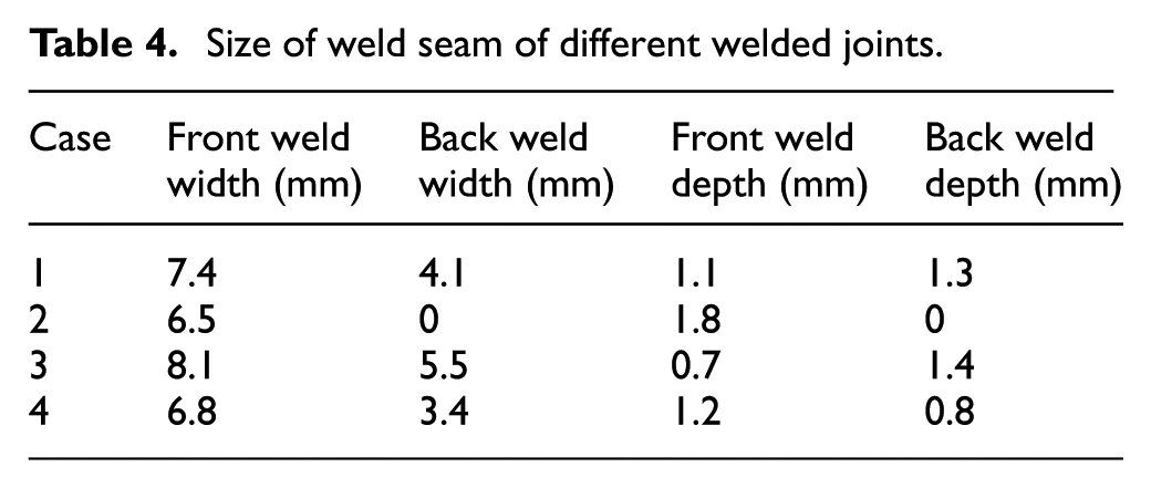
The average weld width and weld depth are measured to compare the forming effect of different welded joints as shown in Table 4. Besides, the morphology parameters of cross section of welded joint are exhibited in Figure 5. Comparing case 1 with case 2 and case 3 with case 4, it can be found that the front weld width and back weld width of pulsed MIG welding are wider than that of continuous welding. In addition, the front weld depth of pulsed MIG welding is not deeper than that of continuous welding, while the back weld depth of pulsed MIG welding is deeper than that of continuous welding.
Size of weld seam of different welded joints.
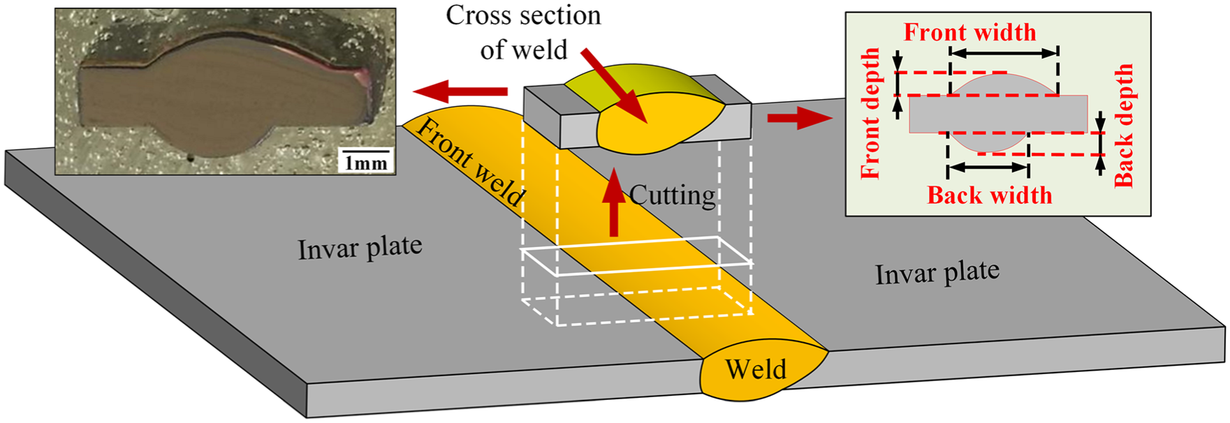
Morphology parameters of cross section of welded joint for Invar alloy plate.
Microstructure
The overall microstructure and the microstructure located in HAZ of the welded joints under different welding parameters are shown in Figures 6 and 7. Different zone of welded joint including based material (BM), HAZ and weld seam zone (WZ) can be identified clearly. Additionally, there is a triangle zone (TZ) whose microstructure is significantly different with surrounding zone to be seen at the bottom of WZ from Figures 6(a) and (c) and 7(a) and (c). The detailed morphology of TZ is presented in Figures 6(d) and 7(d). It can be found that the BM is made of pure austenite grain structure with smaller size. In addition, the coarser austenite grain in HAZ becomes smaller with the increase in the distance from the fusion line as can be seen in Figures 6(b) and 7(b).
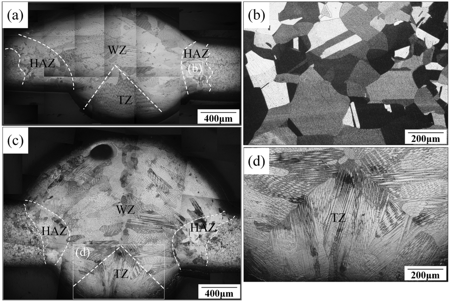
Overall microstructure of welded joint under different welding parameters: (a) overall microstructure of pulsed MIG welding with low heat input, (b) microstructure of HZA marked in (a), (c) overall microstructure of continuous MIG welding with low heat input and (d) microstructure of TZ marked in (c).
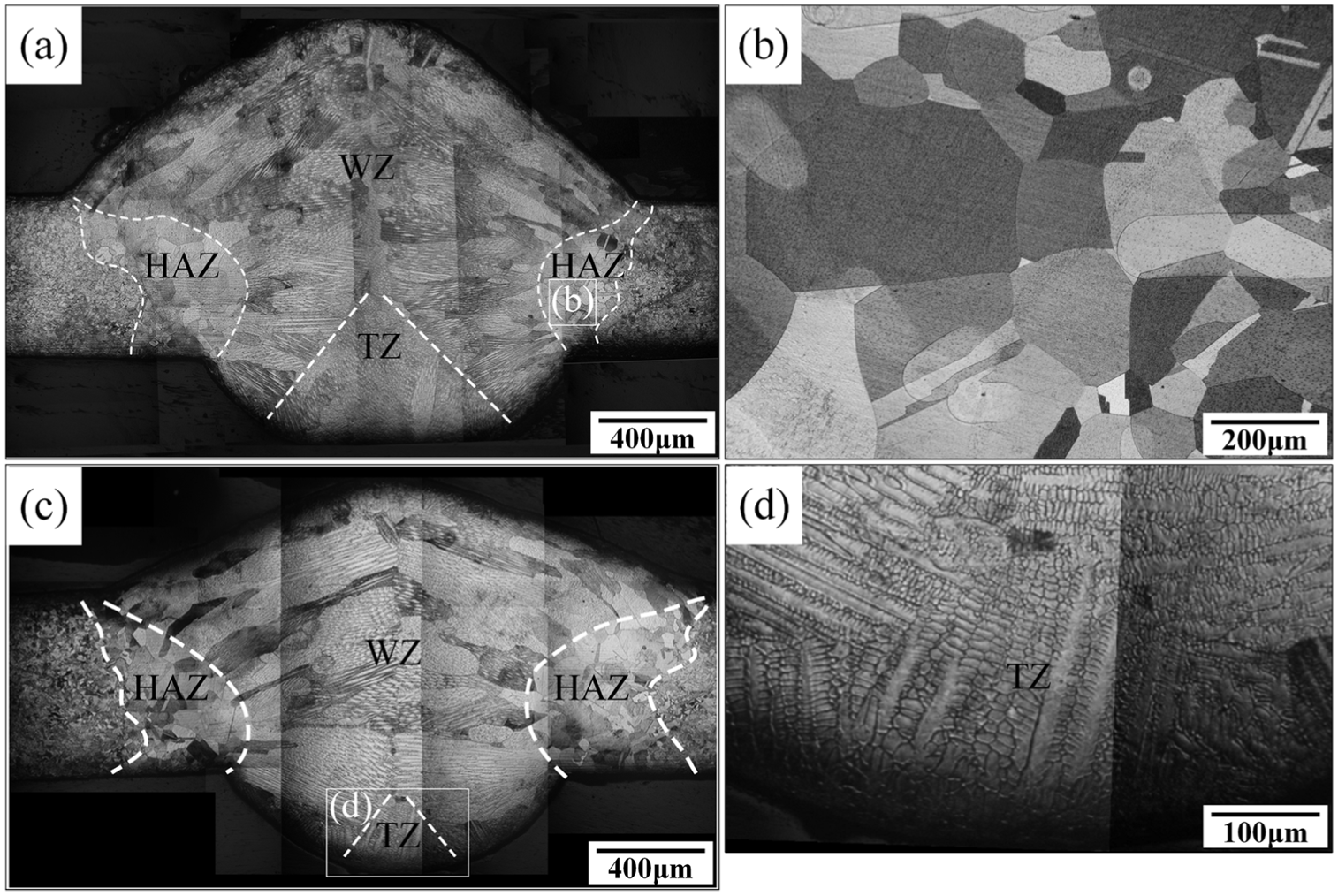
Overall microstructure of welded joint under different welding parameters: (a) overall microstructure of pulsed MIG welding with high heat input, (b) microstructure of HZA marked in (a), (c) overall microstructure of continuous MIG welding with high heat input and (d) microstructure of TZ marked in (c).
Figures 8 and 9 show the detailed microstructure located in the WZ of different welded joints. It can be seen that the WZ is filled with columnar grain, columnar dendrite, cellular dendrite, cellular crystal and equiaxed grain. Comparing the microstructure of pulsed MIG welding with continuous MIG welding on Invar alloy plate near fusion zone, some similar features can be seen from Figures 8(c) and (f) and 9(c) and (f). There is a clear boundary between WZ and HAZ. Besides, the WZ near the fusion boundary mainly consists of columnar grain and cellular crystal.
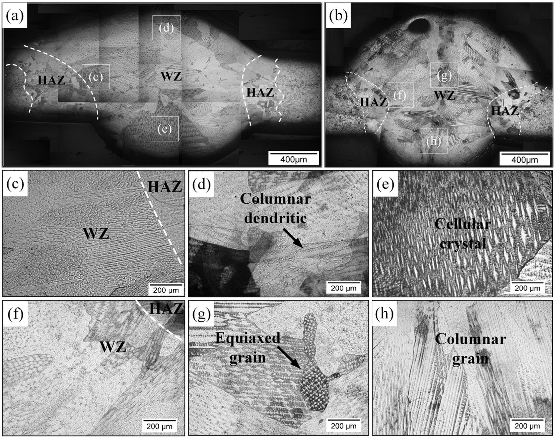
Detailed microstructure of welded joint under different welding parameters: (a) overall microstructure of pulsed MIG welding with low heat input and (b) overall microstructure of continuous MIG welding with low heat input; (c) microstructure near fusion zone in pulsed MIG welding with low heat input; (d) microstructure at the top of WZ in pulsed MIG welding with low heat input; (e) microstructure at the bottom of WZ in pulsed MIG welding with low heat input; (f) microstructure near fusion zone in continuous MIG welding with low heat input; (g) microstructure in the center of WZ in continuous MIG welding with low heat input; (h) microstructure at the bottom of WZ in continuous MIG welding with low heat input.
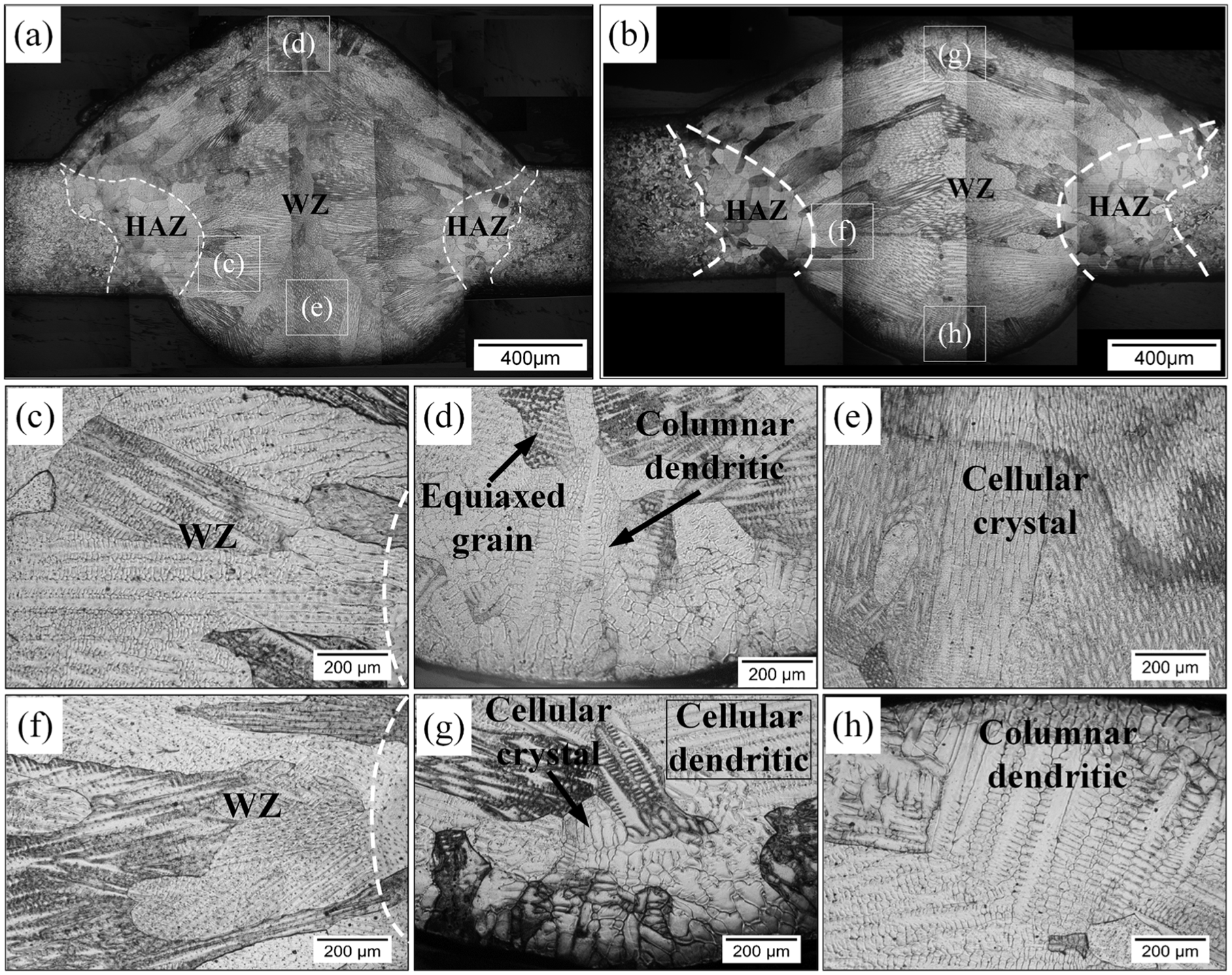
Detailed microstructure of welded joint under different welding parameters: (a) overall microstructure of pulsed MIG welding with high heat input and (b) overall microstructure of continuous MIG welding with high heat input; (c) microstructure near fusion zone in pulsed MIG welding with high heat input; (d) microstructure at the top of WZ in pulsed MIG welding with high heat input; (e) microstructure at the bottom of WZ in pulsed MIG welding with high heat input; (f) microstructure near fusion zone in continuous MIG welding with high heat input; (g) microstructure at the top of WZ in continuous MIG welding with high heat input; (h) microstructure at the bottom of WZ in continuous MIG welding with high heat input.
Comparing the microstructure located in the TZ, it is distinctly different that the TZ of pulsed welding is filled with cellular crystal, whereas the TZ of continuous welding is filled with columnar grain by comparing Figure 8(e) with Figure 8(h) and Figure 9(e) with Figure 9(h). In addition, the obvious columnar dendrite can be seen in Figure 9(h) and the primary dendrite spacing in Figure 9(h) is larger than that in Figure 8(h). Furthermore, it can be seen that the microstructure in the top of WZ consists of typical columnar dendrites in pulsed welding from Figures 8(d) and 9(d), while the microstructure in the same location is made of cellular crystal or equiaxed grain in continuous welding as shown in Figures 8(g) and 9(g).
There is an interesting phenomenon as presented in the middle of WZ. The equiaxed grain can be found in the middle of WZ under continuous MIG welding with low heat input from Figure 8(g). However, when the heat input increases, the equiaxed grain occurs in pulsed MIG welding as shown in Figure 9(d).
Mechanical properties
The mechanical properties including the tensile property, microhardness and fracture morphology are concerned in this study. Therefore, the difference between the pulsed MIG welding and the continuous MIG welding is achieved.
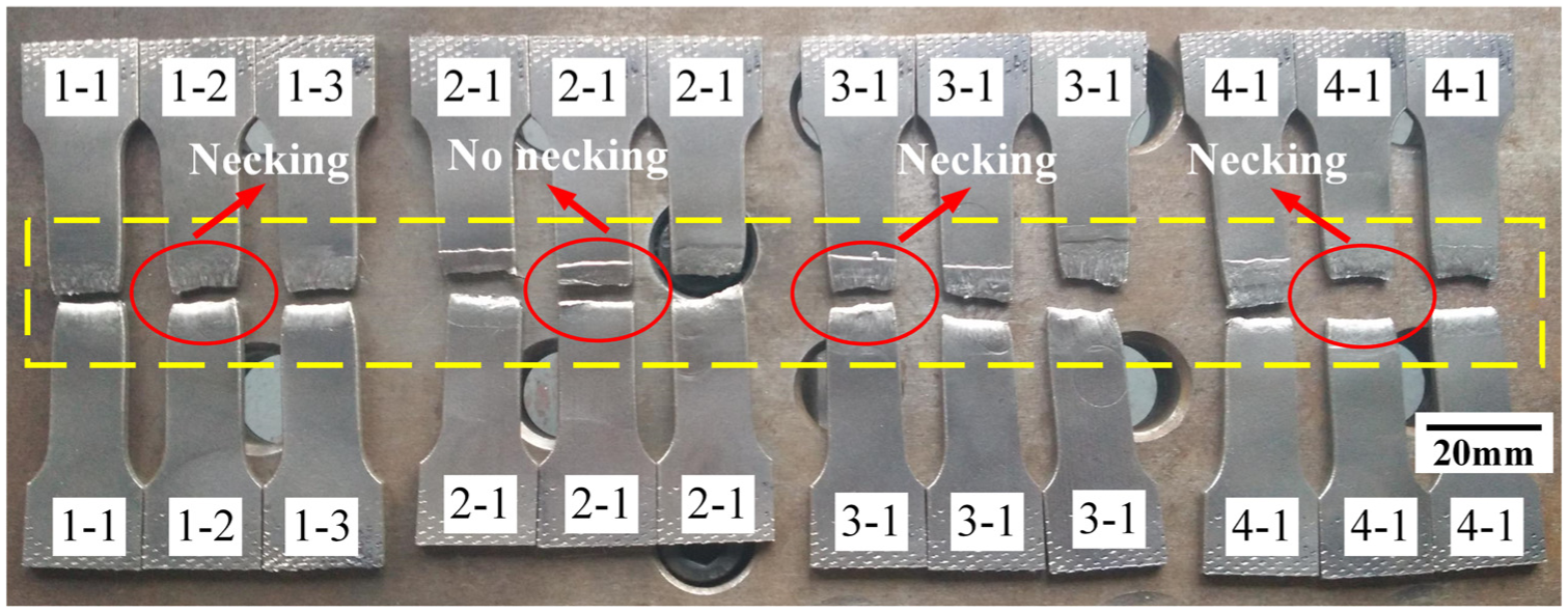
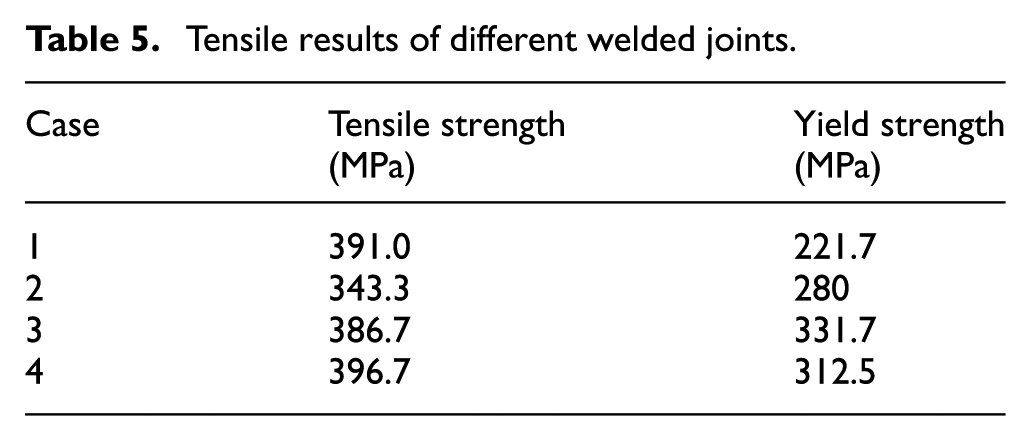
Figure 10 shows the fracture specimen in tensile test. It can be found that the fracture occurs in welded joint of tensile specimen. The result of tensile test is presented in Table 5, including average ultimate tensile strength and yield strength of each group specimen. It can be seen that the tensile strength of all welded joints is lower than that of BM. Comparing case 1 with case 3 and case 2 with case 4, it can be obtained that the ultimate tensile strength of pulsed welded joint with low heat input is stronger than that of continuous welded joint with low heat input. However, the ultimate tensile strength of pulsed welded joint is weaker than that of continuous welded joint when the heat input increases.
Fracture results of different welded joints in tensile test.
Tensile results of different welded joints.
Microhardness distribution curves across the transverse cross section of pulsed and continuous welded joints are presented in Figures 11 and 12, respectively. As shown in Figure 11, the microhardness of pulsed welded joint is apparently higher than that of continuous welded joint with low heat input. In addition, it can be seen that the microhardness of pulsed welded joint is higher than that of base metal. Besides, the microhardness distribution of the pulsed welded joint and continuous welded joint is nearly symmetric about the center of the WZ with high heat input as can be seen in Figure 12. There is no significant difference during pulsed and continuous welding about the microhardness except that the microhardness near the WZ center in pulsed welding is higher than that in continuous welding in the same position.
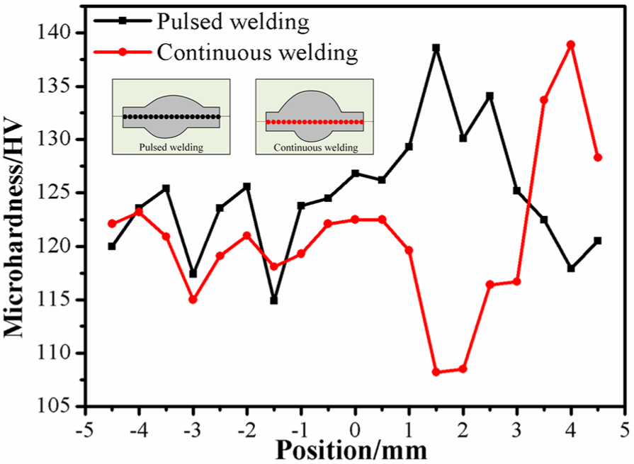
Microhardness distribution of pulsed MIG welding and continuous MIG welding joints with low heat input.
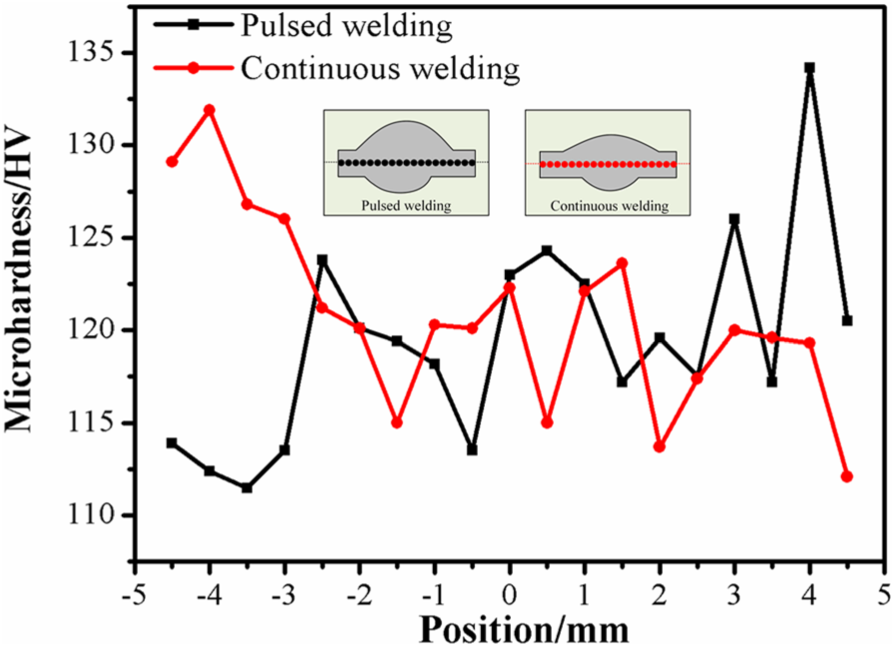
Microhardness distribution of pulsed MIG welding and continuous MIG welding joints with high heat input.
The fracture morphology of pulsed welded joint and continuous welded joint is shown in Figure 13, in which Figure 13(a)–(d) corresponds to cases 1–4 in Table 4. It can be seen that the fracture surface in tensile test is filled with dimples which is the typical character of ductile fracture from Figure 13(a)–(d). In addition, some spherical particles can be found in these dimples of each fracture case as shown in Figure 13(e)–(h). Energy dispersive spectrometer (EDS) analysis result shows that these particles in pulsed welding and continuous welding are mainly made of five kinds of elements including C, Al, Mn, Fe and Ni as shown in Figure 14.
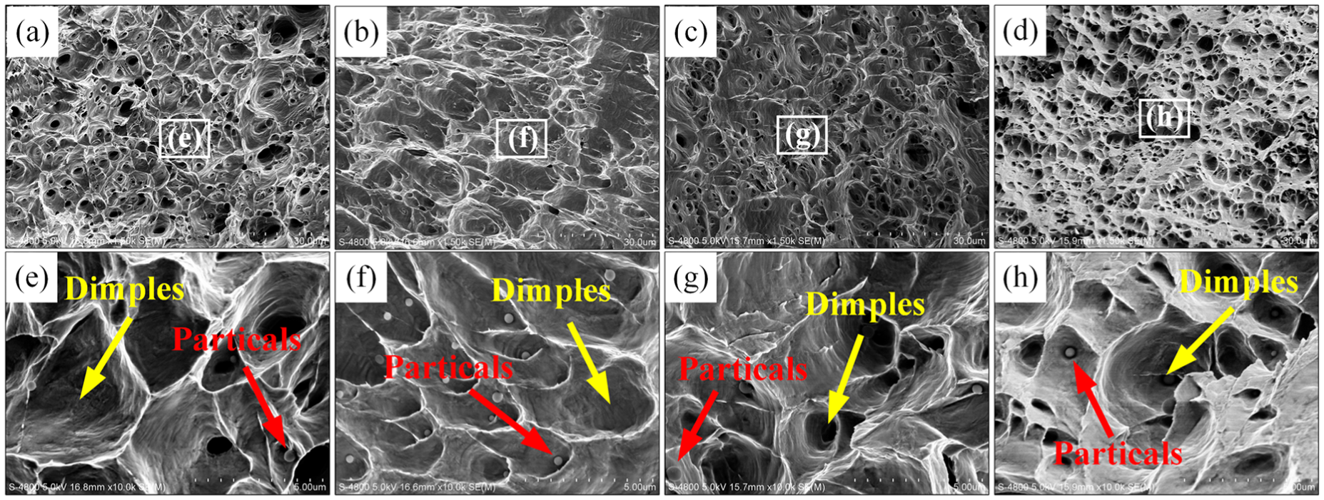
Fracture morphologies of tensile specimens: (a) fracture morphology of case 1; (b) fracture morphology of case 2; (c) fracture morphology of case 3 and (d) fracture morphology of case 4; (e) fracture morphology marked in; (f) fracture morphology marked in; (g) fracture morphology marked in; (h) fracture morphology marked in.
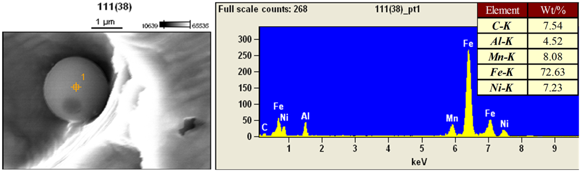
EDS test result of the particles in fractured tensile specimens.
Discussion
It can be found that there are some differences between the pulsed MIG welding and continuous MIG welding from obtained experiment results. The essential reason causing these differences is the mode of welding current. Different welding current has greatly influenced the forming of droplet metal from tip of the torch tip to the molten pool in the welding process. During the pulsed MIG welding, the droplet metal can be only produced when the pulsed current is larger than the critical current. Besides, the current that is lower than the critical current is only used to keep the arc burning as shown in Figure 15. However, the continuous current adopted in continuous MIG welding can produce continuous droplet metal in the welding process. The different mode of the droplet metal has an effect on the heat input and arc pressure for the welding molten pool. Compared with continuous welding, the arc pressure of pulsed welding increases with the increasing frequency of pulsed current. Furthermore, the droplet metal is relatively stable from the torch tip to the molten pool in the continuous welding, but the production of the droplet metal in the pulsed welding periodically varies with the change in the pulsed current. Thus, the stirring effect is formed in the welding molten pool.26,27

Mode of droplet transfer in pulsed MIG welding.
As shown in Figures 6 and 7, the formation of TZ is closely related to the crystallization process during the MIG welding. Under the current welding parameters, the obvious casting microstructure is presented at the bottom of the WZ. The characteristic TZ appears in the WZ as a result of the comparative growth of grain in the molten pool. In addition, the stirring effect of pulsed MIG welding has a great influence on the microstructure located in the TZ, which can destroy the formation of columnar grain and large grain. Therefore, the microstructure in the TZ of pulsed welding presents cellular crystal structure, while the microstructure in the TZ of continuous welding consists of distinct columnar grain.
The morphology of weld seam with different welding parameters is obviously different, which is determined by the welding heat input and the characteristic of welding arc. Comparing case 1 with case 3 and case 2 with case 4, it can be found that the size of weld seam increases with increasing in welding heat input. In addition, the front depth of pulsed welding is smaller than that of continuous welding and the back depth of pulsed welding is deeper than that of continuous welding. These observations can be attributed to the greater arc pressure in pulsed welding. Specifically, the greater pulsed arc pressure can make the liquid metal in the molten pool move down more so that the penetration in the pulsed welding is deeper.
The microstructure in WZ primarily depends on the solute concentration, temperature gradient and crystallization rate in the molten pool. Besides, the stirring effect is also a crucial factor in the pulsed welding process. Figure 16 shows the relationship between the microstructure in the WZ and crystallization condition. In addition, the grain size is greatly related with the welding heat input and the holding time of liquid welding molten pool. Increasing the welding heat input and the holding time of liquid welding molten pool can enlarge the grain size, which is reflected through comparing Figure 8(h) with Figure 9(h).
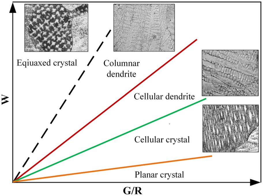
Grain structure growth in welding process: solute concentration W, temperature gradient G and crystallization rate R.
It is worth of being mentioned that the advantage of pulsed welding will not become so significant when the welding heat input increases. As shown in Figures 11 and 12 and Table 5, the tensile strength and microhardness of pulsed welded joint in the low heat input are higher than that of continuous welded joint, while the tensile strength of pulsed welded joint is lower than that of continuous welded joint when the heat input is high. Moreover, the advantageous microhardness of pulsed welded joint in the high heat input is not so obvious. The stirring effect during pulsed MIG welding can make welded joint obtain better microstructure, but the coarsening of grain owing the higher heat input weakens the effect.
Conclusion
The difference between pulsed MIG welding and continuous MIG welding for the 2 mm Invar36 alloy plate is compared by the experimental study for the morphology of weld seam, microstructure and mechanical properties. Following conclusions could be drawn:
Both pulsed MIG welding and continuous MIG welding are suitable for 2 mm Invar36 alloy plate under rational welding parameters. The size of front width and back depth of weld seam obtained in pulsed welding is larger than that of continuous welding, while the size of front depth and back width in pulsed welding is not larger than that in continuous welding.
There is a TZ at the bottom of WZ in pulsed MIG welding and continuous MIG welding on Invar36 alloy. The microstructure in TZ of both welding process is distinctly different, in which the TZ of pulsed welding is filled with cellular crystal while the TZ of continuous welding is composed of columnar grain.
In the reasonable welding parameters, the pulsed MIG welding is significantly better than the continuous MIG welding for the Invar36 alloy. The tensile strength and the microhardness of pulsed MIG welded joint are higher than that of continuous MIG welded joint. Under the lower heat input, the tensile strength of pulsed MIG welded joint is 12.2% higher than that in continuous MIG welded joint. However, the advantage will become lower when the welding heat input exceeds a certain range.
Footnotes
Declaration of conflicting interests
The author(s) declared no potential conflicts of interest with respect to the research, authorship and/or publication of this article.
Funding
The author(s) received the following financial support for the research, authorship, and/or publication of this article: This study is supported by “the Fundamental Research Funds for the Central Universities,” NO. NS2015058.