
Abstract
Dynamics of robot wrist is concerned with the relations between the forces acting on the robot wrist mechanism and the accelerations it produces. Many valuable contributions come forth in recent years, as a suitable dynamics model for a robot wrist is very crucial for analysing its behaviour, on-line control of motions and forces, trajectory design and optimization, and design of robot mechanisms. However, current researches always focus on full-actuated robot wrists. The proposed underactuated robot wrist is a novel mechanism with fewer actuators than the degrees of freedom. As the existing dynamics models for the full-actuated robot wrists are not suitable for the underactuated robot wrist anymore, the dynamics model of the underactuated robot wrist becomes an important issue. This article is devoted to a model for dynamics analysis of a novel underactuated robot wrist. After this underactuated robot wrist is introduced, the dynamics analysis of the underactuated robot wrist with numerical simulation based on virtual prototyping is proposed in detail. The peak values of servo motor in the joint motion unit are also estimated. The dynamics analysis of a novel underactuated robot wrist is used to demonstrate the proposed method.
Introduction
The robot has become a high-tech product to enable fast and reliable operations in manufacturing, transportation, earth and space exploration, assembly and packing, and surgery, and so on. 1 For instance, automotive assembly is one of the typical industrial applications of robots.2–4 A heavy actuator, such as a motor, is always assembled in each of the joint for these traditional robots, which might result in low agility, suitability, applicability, and stability. 5 Generally speaking, there are three approaches to achieve lightweight structure, such as structural optimization, lightweight material, and novel principle solution. With the limitations of lightweight materials and structural optimization, 6 the weight of the robots is still an issue to be solved when the number of actuators is same with the degrees of freedom (DOFs). According to the number of actuators and DOFs, there are three kinds of mechanisms: full-actuated, redundant actuated, and underactuated mechanisms.7,8 As the underactuated mechanism has fewer actuators than its DOFs,9,10 it is widely used in underwater robots, space robots, and other flexible robots. The passive joints, which are always assumed to be driving variables, are not driven by actuators. Thus, the underactuated mechanism is a novel principle solution to lightweight design.
Robot wrists serve as the connection between the robot arms and the end-effectors. As the medium of the position and orientation of end-effectors, robot wrists are the key components for dexterous operations.11,12 The existing full-actuated robot wrist mechanisms could be divided into two basic types: serial mechanism13–15 and parallel mechanism.16–19
However, current researches on dynamics analysis always focus on full-actuated robot wrist, such as Bai and Hansen, 11 Hong et al., 12 Staicu, 16 and Li et al. 19 The underactuated robot wrist is a novel underactuated mechanism, which is usually lighter weight, smaller volume, lower energy consumption, higher flexibility, and lower cost than the traditional full-actuated robot wrist. Thus, to reduce bulk, weight, and expense, designing a robot wrist with fewer actuators than DOFs becomes feasible by introducing mechanical elements to non-holonomic constraints.20,21 As the existing dynamics models of full-actuated robot wrists are not suitable for the underactuated robot wrist anymore, the dynamics model of the underactuated robot wrist becomes an important issue to analyse its behaviour, on-line control of motions and forces, trajectory design and optimization, and design of robot mechanisms, and so on.
As complementary to kinematics,22–24 dynamics is concerned with the study of forces, torques, and their effects on motion, 25 which specifically includes forward dynamics analysis and inverse dynamics analysis. In the forward dynamics, the forces are given to calculate the resulting motions, while in the inverse dynamics the forces are discovered to achieve the desired behaviour of a given system.
There are some differences between the dynamics between underactuated mechanisms and full-actuated mechanisms. In the forward dynamics analysis of underactuated mechanism, the force to achieve the joint angle value of passive joint is assumed as a driving variable which is detected by an independent sensor. The forces to achieve the detection values of angle sensor and the driving joint angle values derive the forward dynamics analysis of the underactuated mechanism. In the inverse dynamics analysis, the force to achieve the angle value of passive joint is taken as the value of desired angle sensor detection.
After the kinematics model of the underactuated robot wrist was proposed in He et al., 22 the objective of dynamics analysis for the underactuated robot wrist is to set up mathematical equations to describe its dynamics models. It is of great importance to describe the mechanical properties of the system with mathematical equations, which is benefit for the control and optimization of the mechanical system. As a non-holonomic mechanical system,20,21 Lagrange equation could be used to solve the dynamics equations for the underactuated robot wrist. In Lagrange equation, the external forces in the generalized coordinates include two parts, one is on the driving joints and the other is on the passive joints, but the force on the passive joints is 0. 22
This article is devoted to the dynamics analysis of a novel underactuated robot wrist. The remainder of this article is organized as follows. Section ‘Introduction of a 3-DOF underactuated robot wrist’ introduces a novel underactuated robot wrist. Section ‘Dynamics analysis of the underactuated robot wrist’ provides dynamics analysis of the underactuated robot wrist. Section ‘Dynamics simulation of the underactuated robot wrist’ simulates a virtual prototyping–based dynamics model to verify the results of the above dynamics analysis. As the peak values of driving torque and speed for servo motor are important results to dynamics analysis, section ‘Estimation of peak value of servo motor’ estimates the peak values of servo motor in the joint motion unit. Section ‘Conclusion’ concludes this article.
Introduction of a 3-DOF underactuated robot wrist
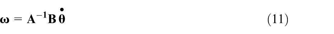
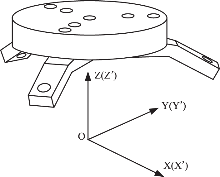
The proposed 3-DOF underactuated robot wrist has been authorized for patent by the National Intellectual Property Office of China. 26 As shown in Figure 1, the 3-DOF underactuated robot wrist is composed of a static platform Q, a moving platform P, three symmetric connecting branches L11–L12, L21–L22, L31–L32 with the same interval angle of 120° assembled with several hinge pins, and two actuators with interval angle of 120°. As a kind of 3-RRR (RRR donates three serial revolute pairs) spherical mechanisms, 27 all the axes of the linkages, that is, L11, L12, L21, L22, L31, and L32, in these branches of the underactuated robot wrist, intersect at the same point O. 28 The coordinate system Oij-XijYijZij (i, j = 1, 2, 3) is set up with the jth rotation joint in the ith branch. The structure model of the underactuated robot wrist is shown in Figure 2.
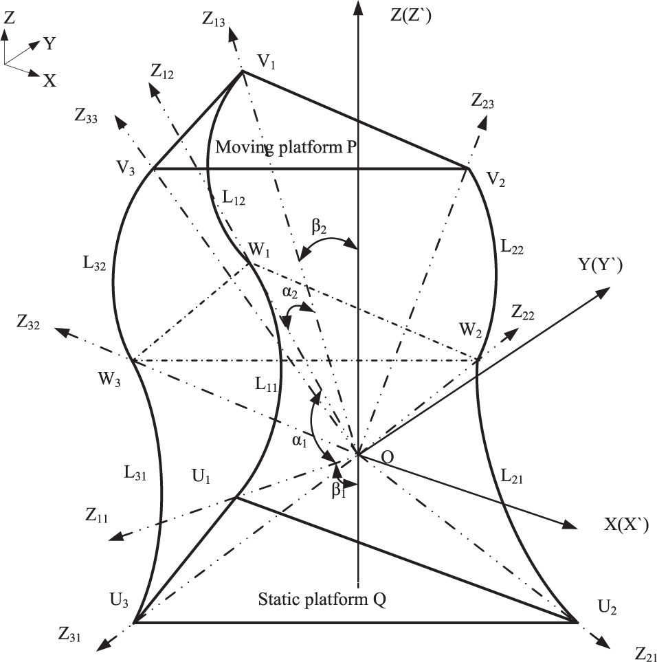
The coordinate system of the underactuated robot wrist.
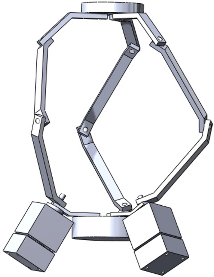
The structure model of the underactuated robot wrist.
The underactuated robot wrist has following basic design parameters:
α1: α1 is the structure angle of the active link, which is the angle between the Zi1-axis and the Zi2-axis, i = 1, 2, 3.
α2: α2 is the structure angle of the passive link, which is the angle between the Zi3-axis and the Zi2-axis, i = 1, 2, 3.
β1: β1 is the semi-cone angle formed by the static platform with the range from 0° to 90°, which is the angle between the Zi1-axis and the Z-axis.
β2: β2 is the semi-cone angle formed by the moving platform with the range from 0° to 90°, between the Zi3-axis and the Z′-axis.
Because the 3-DOF underactuated robot wrist owns three symmetric connecting branches, the three structure angles between the Z11-axis and Z12-axis, Z21-axis and Z22-axis, and Z31-axis and Z32-axis must be equal. Here, thus, one parameter α1 is used to donate the three different angles between the Z11-axis and Z12-axis, Z21-axis and Z22-axis, and Z31-axis and Z32-axis. The same is for α2, β1, and β2.
Dynamics analysis of the underactuated robot wrist
Jacobian matrix
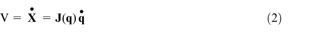
In the coordinate system of the underactuated robot wrist, the moving velocity is
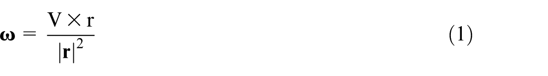
Jacobian matrix of the robot generally refers to a generalized transmission ratio 1 transferred by movement velocity from the joint space to the operation space, that is
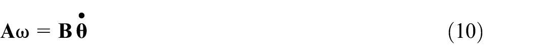
where
For the underactuated robot wrist, the Jacobian matrix could be expressed as
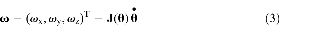
where ω = (ωx, ωy, ωz)T is the angular velocity of the moving platform,
From the inverse kinematics analysis, 22 since the angle between the branch in the middle joint and the joint of the moving platform is fixed as α2

Both sides of equation (4) are differentiated with respect to time t, that is

where

Therefore, the linear velocity of the unit vector
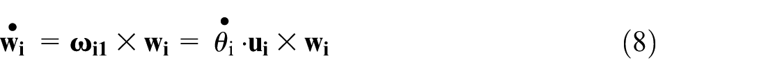
Substituting equations (6) and (8) into equation (5), then it could be expressed as follows
thus
and
where
Hence, Jacobian matrix of the underactuated robot wrist is
Rotation matrix
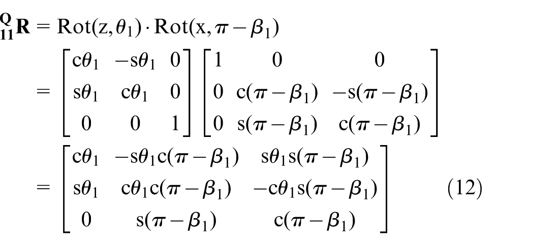
The rotation matrix should be solved to describe the motion characteristics for the linkage of the underactuated robot wrist. There are three branches: branch 1 (L11–L12), branch 2 (L21–L22), and branch 3 (L31–L32). As an example, the linkage coordinate system of branch 1 L11–L12 is created according to the method based on Denavit-Hartenberg Matrix(D-H method), as shown in Figure 3.
The coordinate system of branch 1.
The rotation matrix of linkage L11
The coordinate system O-X11Y11Z11 of linkage L11 could be coincided with the coordinate system O-XYZ by the following steps:
Rotate an angle of θ1 about the Z-axis, which makes the X11-axis align with the X-axis.
Rotate an angle of π–β1 about the X-axis, which makes the Z11-axis coincide with the Z-axis.
Thus, the rotation matrix of linkage L11 could be obtained as follows
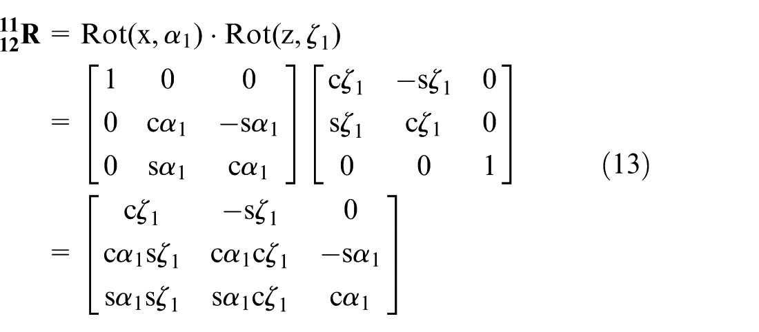
2. The rotation matrix of linkage L12
The coordinate system O-X12Y12Z12 of linkage L12 could be coincided with the coordinate system O-X11Y11Z11 by the following steps:
Rotate an angle of α1 about the X11-axis, which makes the Z12-axis coincide with the Z11-axis.
Rotate an angle of ζ1 about the Z11-axis (ζ1 is the included angle between the X12-axis and the X11-axis), which makes the X12-axis coincide with the X11-axis.
Hence, the rotation matrix of linkage L11 based on the coordinate system O-X11Y11Z11 is given as follows
The angle ζ1 has been obtained in the kinematics model;
22
substituting it into equation (13), the matrix
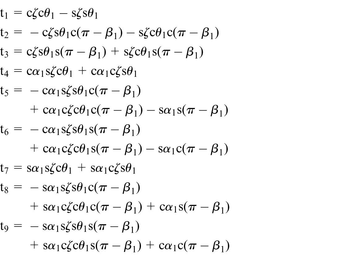
Thus, the rotation matrix of linkage L11 with respect to the coordinate system O-XYZ is given as follows

where
3. The rotation matrix of linkage L21
Set up another reference coordinate system O-X″Y″Z″, to make the point O coincide with the centre of the sphere, make the Z″-axis align with the Z-axis, and ensure the X″-axis perpendicular to the plane determined by the Z″-axis and the Z21-axis, namely, X″ = Z″ × Z21. The coordinate system O-X21Y21Z21 of linkage L21 could be coincided with the coordinate system O-X″Y″Z″ by the following steps:
Rotate an angle of θ2 about the Z″-axis, which makes the X21-axis align with the X″-axis.
Rotate an angle of π–β1 about the X″-axis, which makes the Z21-axis coincide with the Z″-axis.
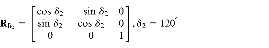
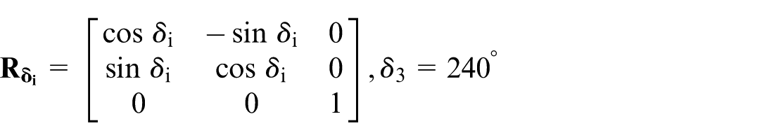
Rotate the reference coordinate system O-X″Y″Z″ by an angle 120° about the Z-axis, which will now coincide with the fixed coordinate system. The corresponding rotation matrix is given by

where
4. The rotation matrix of linkage L22
The coordinate system O-X22Y22Z22 of linkage L22 could be coincided with the coordinate system O-X21Y21Z21 by the following steps:
Rotate an angle of α1 about the X21-axis, which makes the Z22-axis coincide with the Z21-axis.
Rotate an angle of ζ2 about the Z21-axis (ζ2 is the included angle between the X22-axis and the X21-axis), which makes the X22-axis coincide with the X21-axis.
Hence, the rotation matrix of the linkage L22 with respect to the coordinate system O-XYZ is given as follows

5. The rotation matrix of linkage L31
Set up another reference coordinate system O-X‴Y‴Z‴, to make the point O coincide with the centre of the sphere, make the Z‴-axis align with the Z-axis, and ensure the X‴-axis perpendicular to the plane determined by the Z‴-axis and the Z31-axis, namely, X‴ = Z‴ × Z31. The coordinate system O-X31Y31Z31 of linkage L31 could be coincided with the coordinate system O-X‴Y‴Z‴ by the following steps:
Rotate an angle of θ3 about the Z‴-axis, which makes the X31-axis align with the X‴-axis.
Rotate an angle of π–β1 about the X‴-axis, which makes the Z31-axis coincide with the Z‴-axis.
Rotate the reference coordinate system O-X‴Y‴Z‴ by an angle 240° about the Z-axis, which will now coincide with the fixed coordinate system. The corresponding rotation matrix is then given as

6. The rotation matrix of linkage L32
The coordinate system O-X32Y32Z32 of linkage L32 could be coincided with the coordinate system O-X31Y31Z31 by the following steps:
Rotate an angle of α1 about the X31-axis, which makes the Z32-axis coincide with the Z31-axis.
Rotate an angle of ζ3 about the Z31-axis (ζ3 is the included angle between the X32-axis and the X31-axis), which makes the X32-axis align with the X31-axis.
Hence, the rotation matrix of linkage L32 with respect to the coordinate system O-XYZ is given by

Thus, the rotation matrices of all the linkages of the underactuated robot wrist with respect to the fixed coordinate system have been obtained.
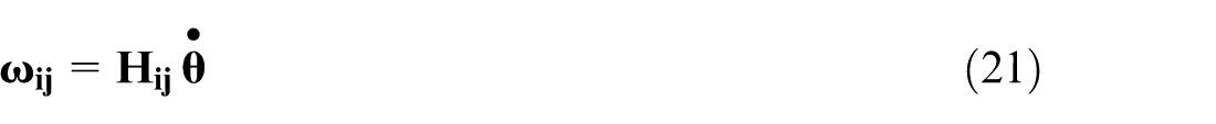
Angular velocity of the linkage
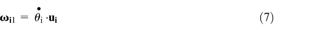
As mentioned above, all the linkages of the 3-DOF underactuated robot wrist rotate about the centre of the spherical mechanism. Accordingly, it could be described by angular velocity. The angular velocity of the driving linkage
The angular velocities of both ends of the joint shaft for the driven linkage Li2 are

Substituting equations (7) and (11) into equation (19), the angular velocity
It has been obtained in the inverse kinematics 22

Thus, the angular velocity of all the linkages of robot wrist is given by
where
Inertial tensor of the linkage
Figure 4 shows the wrist linkage Lij (i, j = 1, 2, 3) based on the structure and the coordinate system of the underactuated robot wrist.
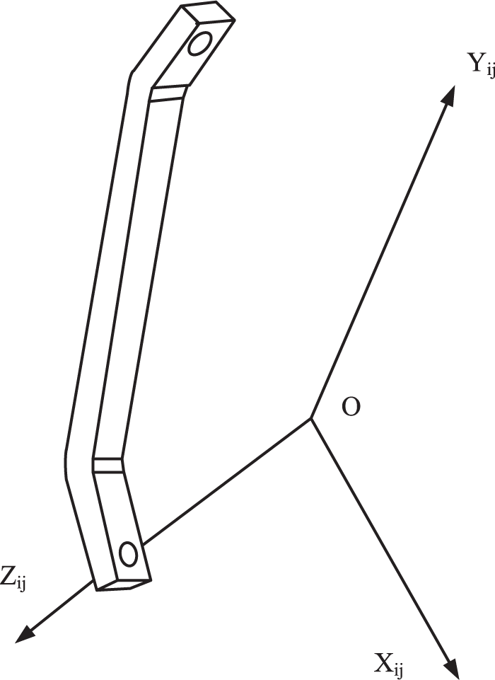
The robot wrist linkage model Lij.
The arched linkage is simplified to a cube with uniform scattered mass, and its centroid is at the centre of the cube. The direction of the coordinate system O′-Xij′Yij′Zij′ at the centre of the cube is identical to the linkage coordinate system O-XijYijZij. The origin of the coordinate system O-Xij′Yij′Zij′ has the coordinate value of (0, 0, rij) measured in the linkage coordinate system O-XijYijZij. rij is the distance between the centroid and the centre of the sphere. The simplified model is illustrated in Figure 5.
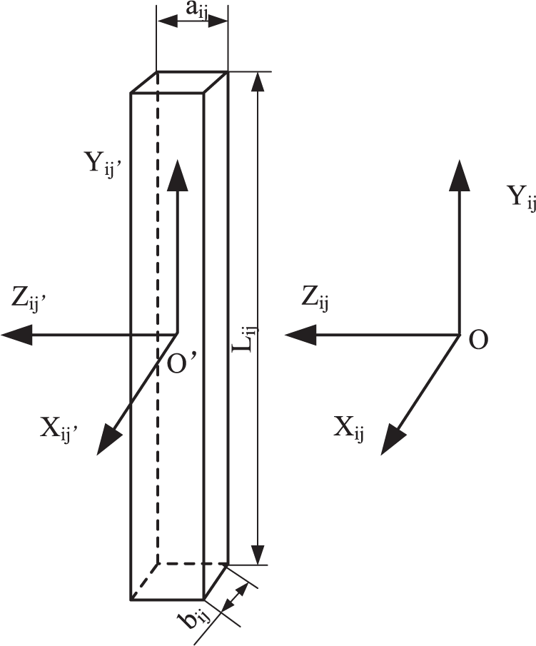
The simplified robot wrist linkage model Lij.
The inertial tensor of linkage Lij with respect to the coordinate system O′-Xij′Yij′Zij′ is given as follows
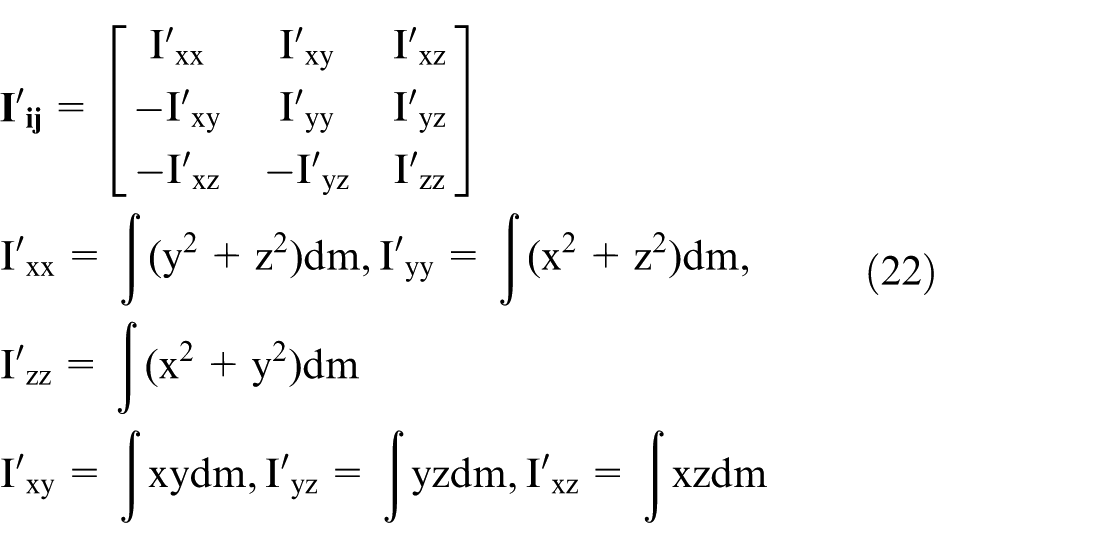
According to the symmetry of cube, the following equation is obtained as
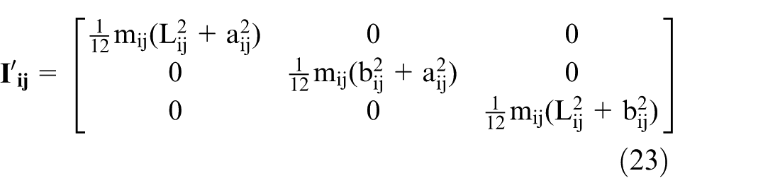
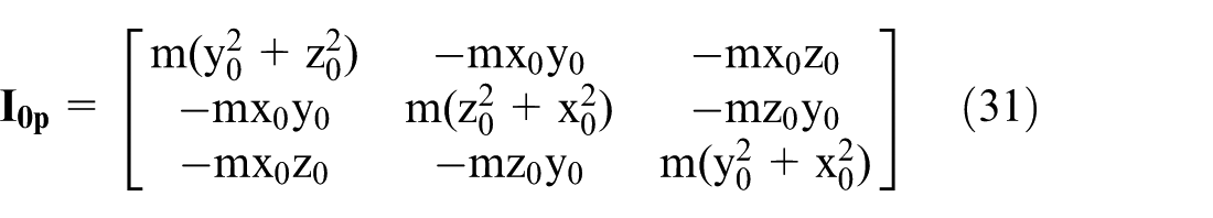
The inertial tensor

where
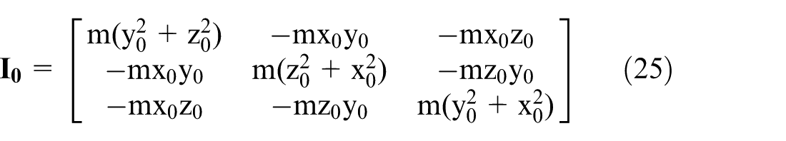
where (x0, y0, z0) = (0, 0, rij) is the coordinate value of the centroid in the coordinate system O-XijYijZij. Substituting it into the above equation, the following expression is obtained
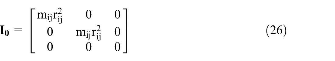

Substituting the rotation matrix obtained in section ‘Dynamics analysis of the underactuated robot wrist’ into equation (27), the inertial tensor of each linkage in the fixed coordinate system O-XYZ could be obtained.
Inertial tensor of moving platform
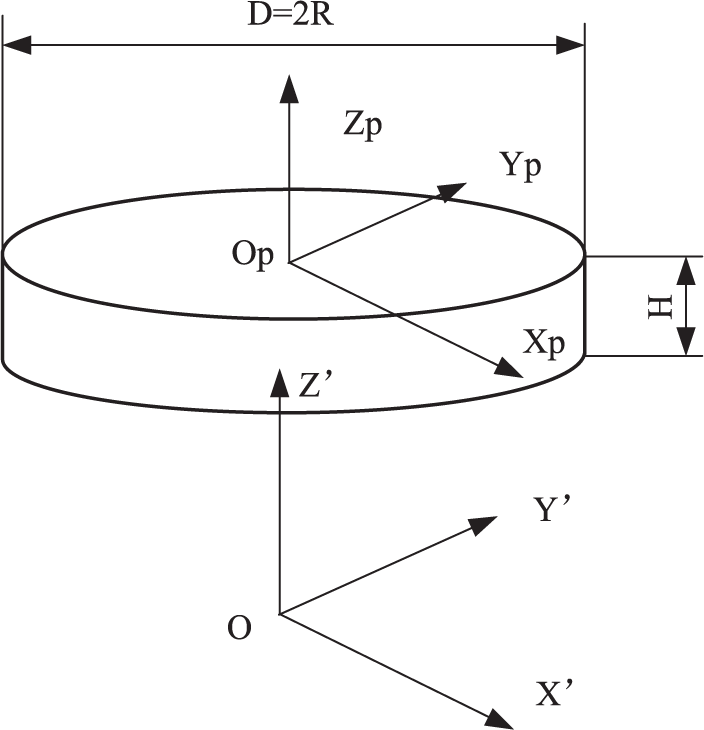
The moving platform model of the robot wrist is shown in Figure 6.
The robot wrist moving platform model.
The O-XYZ coordinate system is fixed on the base platform and the O-X′Y′Z′ coordinate system is fixed on the moving platform. All the arched linkages are simplified into a cylinder with uniform scattered mass; its centroid is at the centre of the cylinder. The direction of the coordinate system Op-XpYpZp at the centre of the cylinder is identical to the moving platform’s coordinate system O-X′Y′Z′. The origin of the coordinate system Op-XpYpZp has the coordinate value of (0, 0, rij) which is measured in the coordinate system O-X′Y′Z′ of moving platform. rp is the distance between the moving platform and the centre of the sphere. The simplified model is shown in Figure 7.
The simplified moving platform of the robot wrist model.
The inertial tensor of the moving platform with respect to the coordinate system Op-XpYpZp is given as
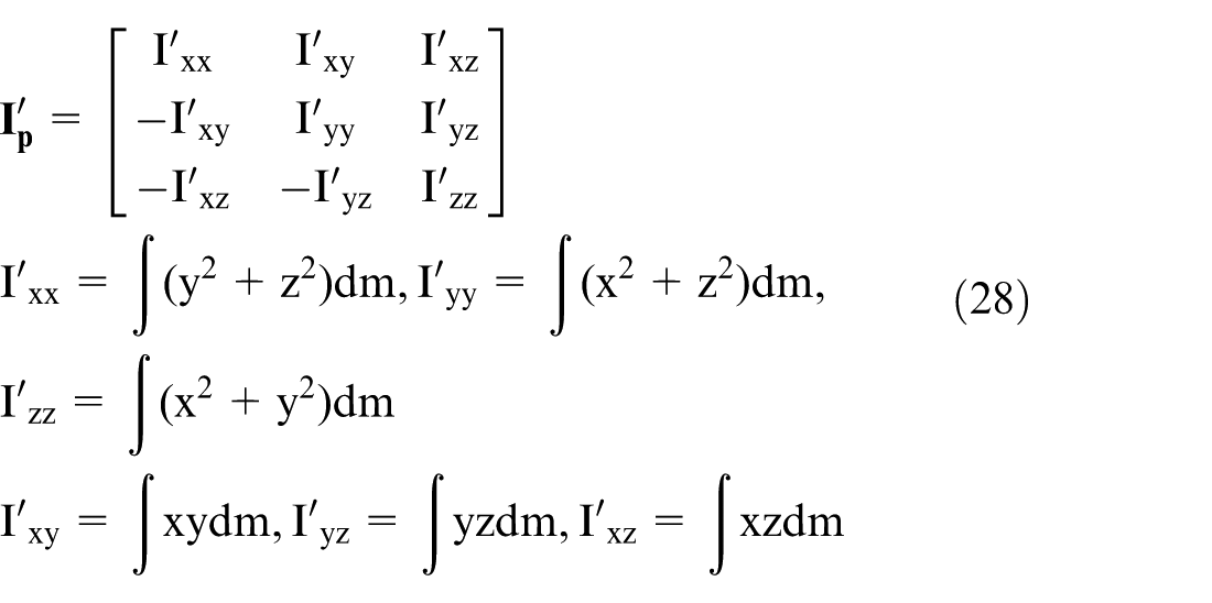
According to the symmetry of the sphere, the following expression is given by
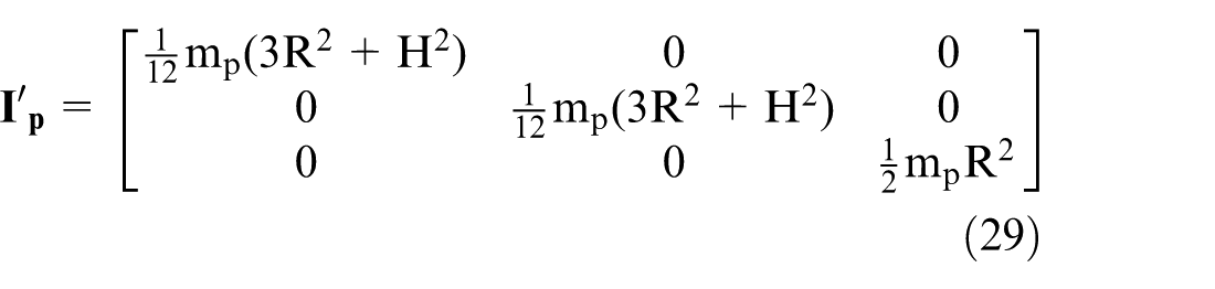
The inertial tensor

where
where (x0, y0, z0) = (0, 0, rij) is the coordinate value of the centroid in the coordinate system O-X′Y′Z′. Substituting it into the above equation, the following expression is calculated as
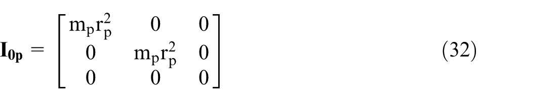
The inertial tensor

Kinetic energy of rigid body
All the moving rigid bodies of the underactuated robot wrist turn around the centre of the sphere. Therefore, they only have rotational kinetic energy without moving kinetic energy. In other words, the kinetic energy of the underactuated robot wrist could be expressed by the rotational kinetic energy of the moving rigid bodies.
According to the rotational kinetic energy theorem, the kinetic energy of the linkage Lij is given by

Similarly, the kinetic energy of the moving platform could be obtained as

The total kinetic energy of the robot wrist is now obtained as follows
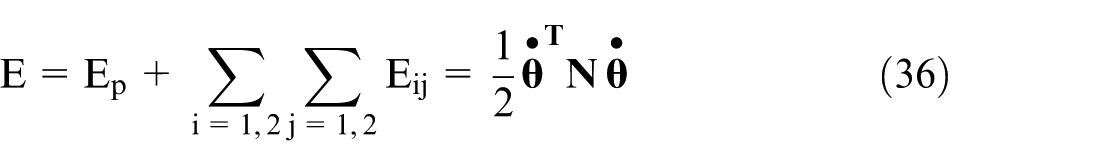
where
Potential energy of rigid body
As shown in Figure 2, the coordinate value of the centroid of linkage Lij is (0, 0, rij) in the linkage coordinate system O-XijYijZij. Thus, the position coordinate of its centroid is
The gravitational acceleration is g with the direction of the Z-axis. Thus, the potential energy of linkage Lij with respect to the fixed coordinate system O-XYZ is given by

As illustrated in Figure 2, the coordinate value of the centroid of the moving platform is (0, 0, rp) in the moving platform coordinate system O-X′Y′Z′. Thus, the position coordinate of its centroid is (QΨ,θ,Φ·(0, 0, rp)T)T = (0, 0, hp) in the fixed coordinate system O-XYZ, which means the coordinate value, from the Z-axis direction, of the centroid is hp in the fixed coordinate system O-XYZ.
The potential energy of the moving platform with respect to the fixed coordinate system O-XYZ could be obtained as

The total potential energy of the robot wrist is now obtained as follows
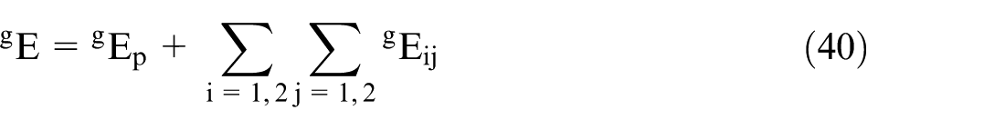
where Eij and Ep are the functions of joint variables θ1, θ2, and θ3.
Dynamics equation
The dynamics equation could be obtained according to the total kinetic and potential energies of the mechanical system; the Lagrange equation is then given by

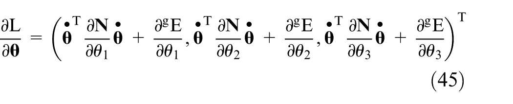
According to the Lagrange equation, 1 the following expression is given as
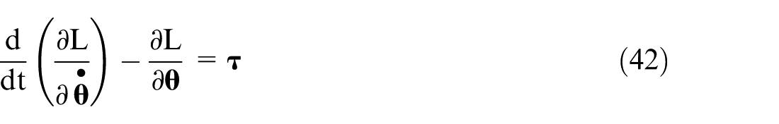
where θ = (θ1, θ2, θ3)T is the generalized coordinate, L is the total energy of the mechanical system, and τ = (τ1, τ2, τ3)T is the external force acting on the generalized coordinate. θ1 and θ2 are the driving joint variables, θ3 is the driven joint variable, and τ3 is equal to 0
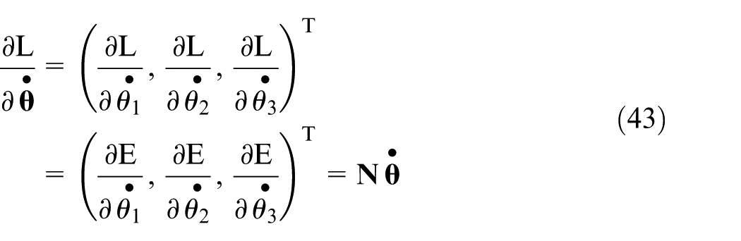
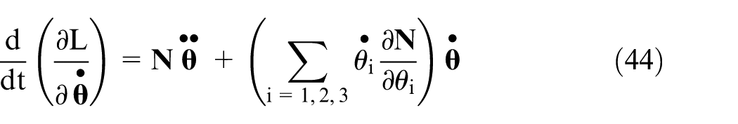
Substituting equations (43)–(45) into equation (38), the kinetic equation of the underactuated robot wrist is then obtained
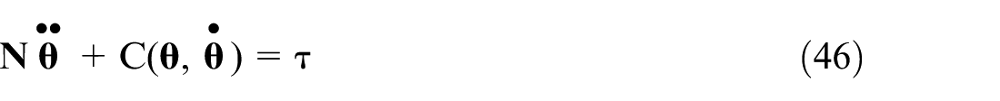
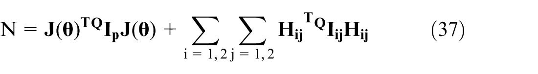
where
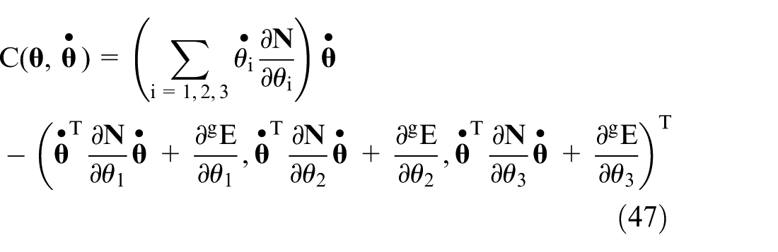
where N is the inertial matrix of the system;


where q = (q1, q2), the item q1 = (θ1, θ2) is the driving joint variable, and the item q2 = θ3 is the driven joint variable
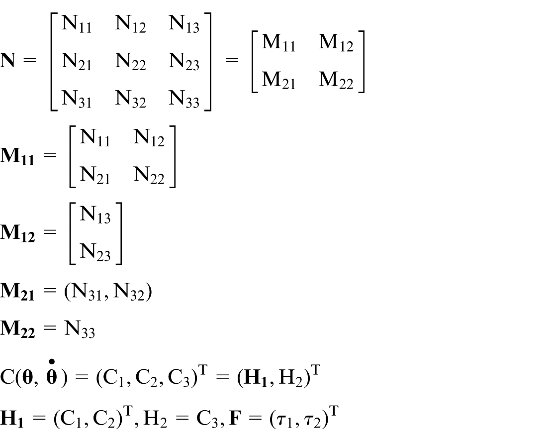
where equation (44) is the driving sub-system of mechanical system and equation (49) is the underactuated sub-system of mechanical system.
In the forward kinematics problem, the input torques of two motors for the underactuated robot wrist are prescribed, and the acceleration of the three driving linkages is then obtained. According to equation (46), the direct kinematics model is given by
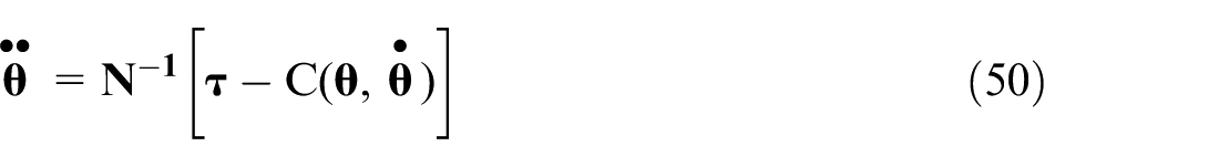
In the inverse kinematics problem, the accelerations of the three driving linkages of the underactuated robot wrist are prescribed, and the input torques of two motors are then obtained. The inverse kinematics model is obtained according to equation (46)
Dynamics simulation of the underactuated robot wrist
The process of dynamics simulation
A Parasolid file of the underactuated robot wrist was imported into ADAMS, which is a dynamics analysis software for mechanical systems. The processes of dynamics simulation are as follows:
1. Set the coordinate system and gravity direction
The spherical coordinate system was set as order 313. Its centre point of the robot wrist is the same as the origin point of the coordinate system. Then set the gravity direction as the Y-axis direction.
2. Change the component name and colour
Change the colour, name, and transparency of each component for easy operations in ADAMS.
3. Specify the material of components
Specify the material of each component. All the components of the underactuated robot wrist are designated as 45 steel (density as 7.8 × 10³ kg/m3).
4. Add constraints and kinematic pairs, then add force, and then add movements
After the coordinate system, gravity direction, component name, and component material are set up; the corresponding constraints and kinematic pairs are set up according to their motion relations. Finally, specify the drive mode of the joints to achieve a predetermined motion. A STEP function is defined in ADAMS, as follows

where x is an autonomous variable, (Begin, Initial Value) decides the information of start, and (End, Final Value) decides the information of end. The value is the initial value when the time’s range is from 0 to Begin, and then increase (or decrease) to Final Value by the time End.
Each input revolution joint driving function is as follows:
Motion-1: STEP (time, 0.0, 0.0, 5, −20d)
Motion-2: STEP (time, 0.0, 0.0, 5, −15d)
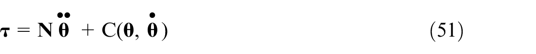
The initial position of the input joint angle is 140°. The driving function Motion-1 represents that one of the inputs is to rotate 20° at 0–5 s from the initial position to the angle of 120°. The drive function Motion-2 represents that another of the inputs is to rotate 15° at 0–5 s from the initial position to the angle of 125°. The simulation model of kinematics analysis has been verified in He et al., 22 as shown in Figure 8. After all the above settings are completed, set the simulation time and the number of simulation steps. Each joint angular velocity, angular acceleration, and joint torque curve over the corner of each joint could be drawn in the simulation processing module ADAMS/PostProcessor.
Virtual prototyping–based underactuated mechanism.
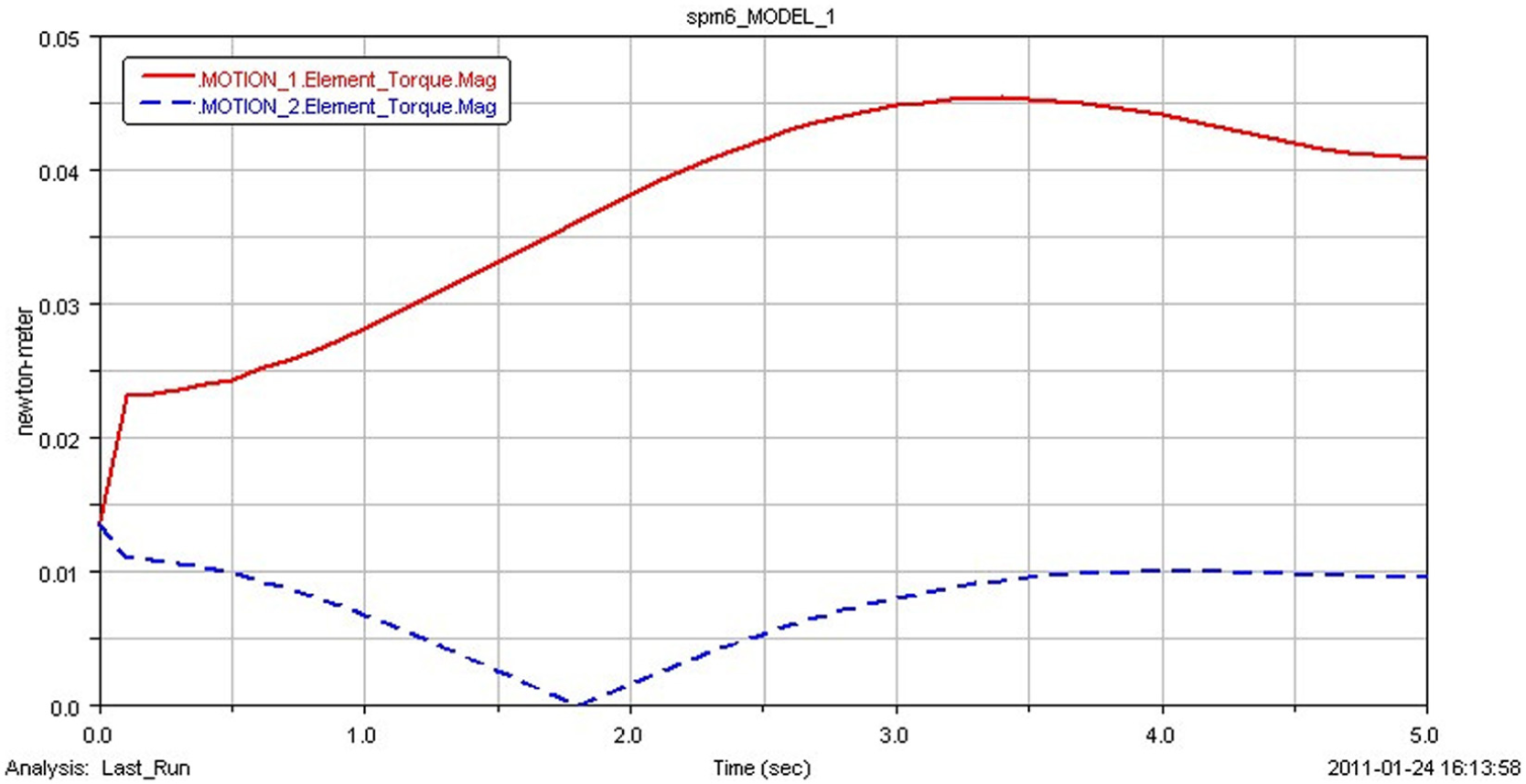
The underactuated robot wrist movement affected by the mechanical friction
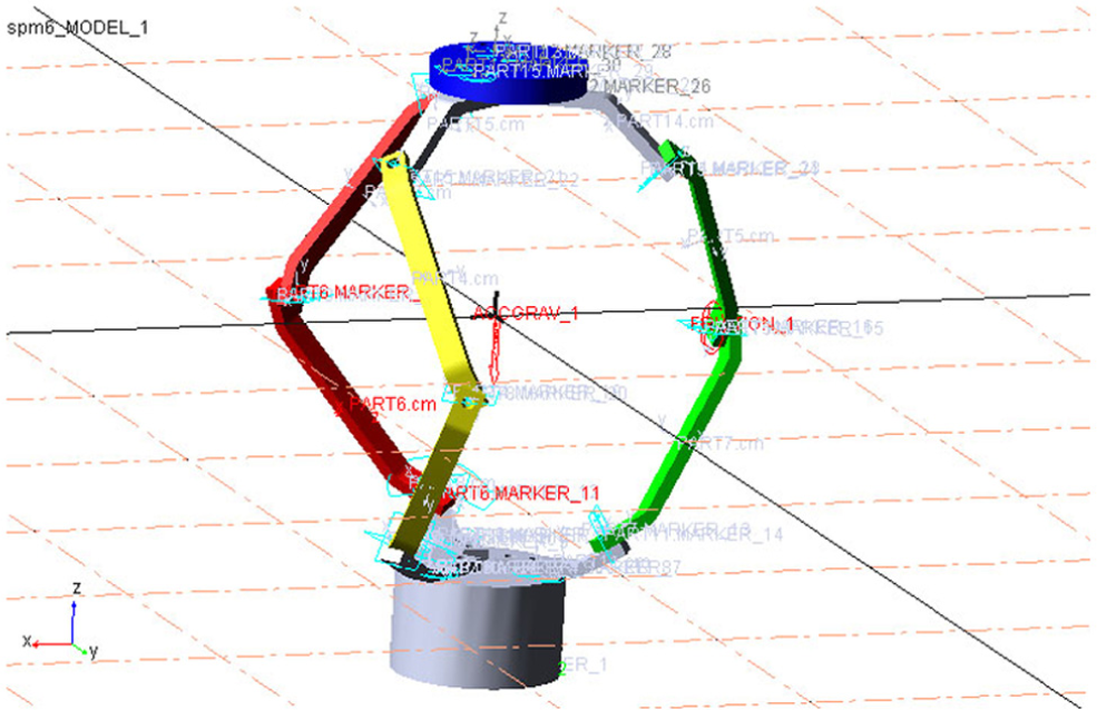
To study the movement of the underactuated mechanism affected by mechanical friction, the mechanical friction of the whole mechanism is ignored at first. The mechanism has a certain oscillation during the process of movement of the driven joints. Figure 9 shows the torque variation curves of two driving joints, which is obtained from the prototype affected by friction in ADAMS.
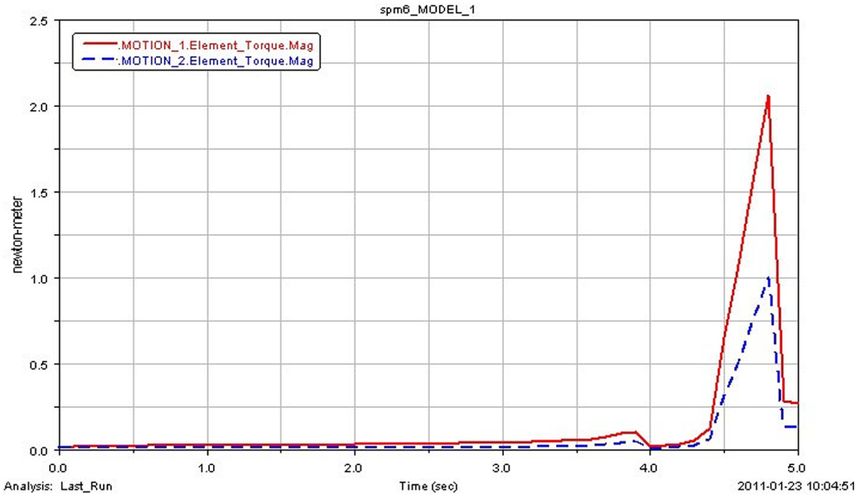
The variation curves of two driving joints.
As illustrated in Figure 9, the torques of two driving joints change between 4 and 5 s frequently, which demonstrates that the mechanism has a slight jitter between 4 and 5 s, because the passive joint is not driven by the motor.
The underactuated wrist movement affected by the speed of the input drive
In comparison, the end time of two driving functions is changed from t = 5 s to t = 20 s in ADAMS as follows:
Motion-1: STEP (time, 0.0, 0.0, 20, −20d)
Motion-2: STEP (time, 0.0, 0.0, 20, −15d)
Meanwhile, when the simulation time is 20 s, other conditions remain unchanged; re-simulate the model and the results are then obtained as below.
By comparing Figure 10 and Figure 9, as the time axis of driving function goes on, the vibration of the passive joint and the moving platform becomes smaller at the end of the movement. It illustrates that the drive speed has some influence on the vibration of moving platform and passive joint.
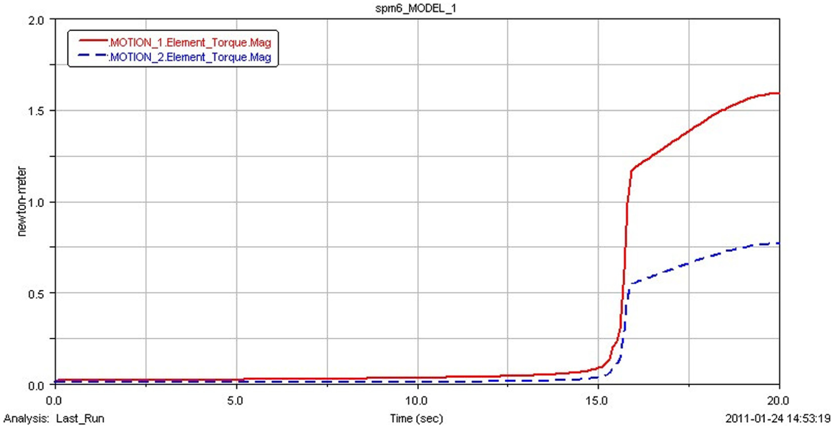
The torque variation curves of two driving joints.
The underactuated wrist movement affected by the input drive
In order to compare the effects of underactuated mechanism movement result from the direction of input drive, the direction of one input drive is changed in ADAMS, that is, the direction of Motion-2 opposites to its original one, as given by
Motion-1: STEP (time, 0.0, 0.0, 5, −20d)
Motion-2: STEP (time, 0.0, 0.0, 5, 15d)
Other conditions remain unchanged; re-simulate the model and the results are then obtained as follows.
As shown in Figure 11, the torque variation curves of two driving joints vibrate at the beginning of the simulation (between 0 and 4 s). The torques of two driving joints are extremely steady between 4 and 5 s during the whole simulation process by comparing Figures 9 and 11. There is no extremely cusp phenomenon in Figure 11, which shows the underactuated mechanism running smoothly in this simulation process. The results mentioned above demonstrate that the drive direction has significant influence on the movement of this underactuated robot wrist.
The torque variation curves of two driving joints with Motion-2.
Estimation of peak value of servo motor
The 3-DOF underactuated robot wrist should have greater velocity and acceleration to achieve quick response. Thus, high driving velocity and torque for servo motor are required. The relations between the movement of the reference point of the moving platform and driving parameters on each joint are analysed, which could provide the basis for the estimation of servo motor parameters. The robot wrist has three branches, in which branch 1 is used to be analysed as an example based on dynamics analysis and symmetry. According to the dynamics analysis, the maximum instantaneous rotational speed of the servo motor on branch 1 is generated in the maximum speed movement process of 3-DOF underactuated robot wrist. From the dynamics analysis, the servo motor of branch 1 produces maximum instantaneous torque when the 3-DOF underactuated robot wrist started up. Consequently, the peak parameters of servo motor could be estimated based on the motion mode that is mentioned above. In order to simplify the calculation and analysis processes, assume that the velocity function of the reference point of the moving platform is a cosine function, and the spatial motion path of reference point is a cosine curve as well. 22
Analysis of driving velocity peak value
In order to analyse the relations between the angular velocity

where J1, J2, and J3 are the velocity transmission Jacobian sub-vector of each driving branch i (i = 1, 2, 3), respectively.
For branch i, the relation between its rotational speed Ni (unit: r/min) of driving motor and the angular velocity

where ni is the transmission ratio of the reducer.
Substituting equation (52) into equation (53), the relation between the driving velocity of servo motor and the velocity of reference point on moving platform is then obtained as

Analysis of driving torque peak value
For branch i, its relation between motor torque

where λi is the transmission coefficient of driving force.
Centrifugal force and Coriolis force are negligible in the analysis of driving torque, because it just considers the rapid start work condition of servo motor. The relation of driving motor and the acceleration of reference point on the moving platform is then obtained as30,31

where
According to the literature,29,30 peak value estimate model of servo motor is given by

Case analysis
On the basis of the parameters in Table 1, the material type is 45 steel, and its density is 7.8 × 10³ kg/m3. Motion functions of the above model in the steady motion period are given as follows
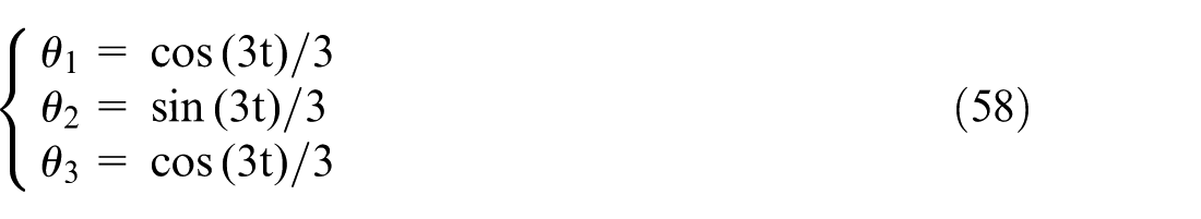
where θ1, θ2, and θ3 are the nutation angles of the first branch, second branch, and the third branch, respectively.
Parameters of the 3-DOF underactuated robot wrist.
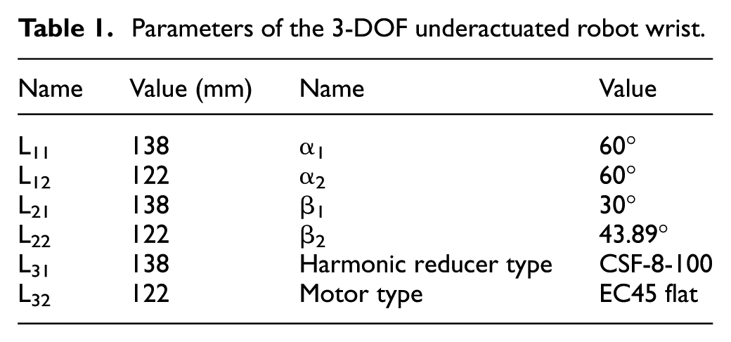
The transmission ratio of the Harmonic reducer CSF-9-100 is 100. The driving rotational speed of servo motors could be calculated according to equation (54). Substituting the motion function, the corresponding rotational speed of servo motor is obtained. The theoretical maximum rotational speed is then obtained accordingly to solve each maximum singular value in equation (54). The maximum rotational speeds of branch 1 and branch 2 are 1630 r/min. The maximum rotational speed of the servo motor EC45 flat is 3000 r/min. Thus, they are smaller than the theoretical maximum speed of the servo motor, which proves the correctness of the theoretical peak estimation of driving velocity.
According to equations (56) and (57), the driving torques of servo motors could be calculated. Substituting the motion function, the corresponding torque of servo motor is obtained. The theoretical maximum torque is then obtained accordingly to solve each maximum singular value in equations (56) and (57). The transmission ratio of the Harmonic reducer CSF-9-100 is 100. The maximum torques of branch 1 and branch 2 are 36.3 m N m. The maximum rotational speed of the servo motor EC45 flat is 58.8 m N m. Thus, they are smaller than the theoretical maximum torque of the servo motor, which proves the correctness of the theoretical peak estimation of torques.
Conclusion
As the existing dynamics models for the full-actuated robot wrists are not suitable for the underactuated robot wrist anymore, the dynamics model of the underactuated robot wrist becomes an important issue. This article is devoted to the dynamics analysis method for an underactuated robot wrist. After a novel underactuated robot wrist was proposed, the inverse dynamics analysis and forward dynamics analysis of the underactuated robot wrist were proposed in detail. The rotational inertia, rotational kinetic energy, and potential energy of rigid body were obtained with the conclusions of kinetics equations. Dynamics equations of the underactuated robot wrist were given through the Lagrange equation, which was divided into actuated sub-system and underactuated sub-system. Meanwhile, the forward and inverse dynamics of underactuated robot wrist were solved. Then the dynamics numerical simulation based on virtual prototyping was also put forward. The underactuated wrist movements with mechanical frictions, different driving speeds, and different driving directions were discussed in detail, and the peak value of servo motor in the joint motion unit was also estimated, which are used to demonstrate the proposed methodology. The dynamics analysis of a novel underactuated robot wrist is used to demonstrate the proposed method.
Several extensions will be done in the future. First, as the underactuated robot wrist has non-holonomic constraints, determining how to achieve the non-holonomic control is a complementarity of the current control theory. Second, since the underactuated robot wrist is a promising area, the type synthesis of the underactuated parallel wrists derived from the full-actuated parallel wrist topology is also an important topic.
Footnotes
Appendix 1
Declaration of conflicting interests
The author(s) declared no potential conflicts of interest with respect to the research, authorship, and/or publication of this article.
Funding
The author(s) disclosed receipt of the following financial support for the research, authorship, and/or publication of this article: This work was supported by National Natural Science Foundation of China (no. 51305249).