
Abstract
The machining of high–added value blades represents a challenge due to the parts’ complex geometry and tight tolerances. Blades are common in the aeronautic, energy or automotive sectors. Nowadays, there is a strong trend towards the integration of all machining operations in the same machine tool platform; this is the so-called multitasking machining. The main advantage is that the part reference system is maintained along all the operations, and it also achieves shorter production lead times. However, milling operations have to be programmed for being performed in machines with a general lathe structure, which must be solved.
For this reason, in this work, advanced programming for the production of blades in turning centres and multitasking machines is developed. Blade machining is developed by successive techniques. This article mainly focuses on the study of the optimal machining strategy for blades turn-milling. For that purpose, different strategies and tilt angles have been tested and applied initially to a test part and finally to a real part. The proposed methodology has been applied to a blade case study in order to obtain the best parameters and toolpath strategies for blades machining. They represent the main novelty and article contribution.
Introduction
State of the art
Machining of complex surfaces is a common issue in several applications such as blades for turbomachinery, forged crankpins, iron casting crankshafts, grooved features of long power shafts and many others. The very complex geometry1,2 of these parts, along with the high material hardness, implies manufacturing complications and therefore high production costs. 3 This is precisely the case of steam turbine blades, whose manufacturing process requires that each blade must be machined starting from a raw black or a pre-shaped forge. Turbine efficiency is higher for lower surface finish roughness; 4 therefore, there is a need of reliable manufacturing processes for these parts. Moreover, global air traffic–level predictions foretell a fast continuous growth, expecting the number of planes to grow at an average of more than 3% each year by 2030.5,6 This rapid growth represents a challenge in aeroengine manufacturing, demanding robust manufacturing, reduction in lead times and cost-efficient solutions. 7 Price is day after day a demanding requirement even in aeronautics, claiming new machining approaches.
Taking this into account, and not only speaking about aeronautical production, there is a global trend towards the performance of all required operations in the same machine tool, following the so-called multitasking approach. The characteristics of the machining centre greatly affect the machining quality of the products it creates, 8 and consequently, traditional machine kinematics has evolved into multitasking machines; even other non-traditional processes such as laser tempering, laser cladding or burnishing are performed in the same machine and workpiece set-up. Computer numerical controls have also evolved to give a solution for turn-mill machining of asymmetric rotational components. 9
Multitasking machines offer many advantages, both economic and technological ones. From the economical point of view, the initial inversion is easily recovered, the production is fastened because operations are performed in the same machine and, at the same time, fixturing times are reduced. 10 Making all operations on the same set-up makes the achievement of design tolerances easy because all machining operations are performed under the same workpiece machining reference. Thus, industrial fair after fair and year after year multitasking machines, turning centres and milling centres are becoming usual in small companies.
Blade manufacturing11,12 must include turning and milling operations. Machining strategies and parameters need to be studied in order to develop turning and milling operations on the same machine. New concepts such as turn-milling, turn-ball-end milling, pinch milling or Y-axis milling turn up when dealing with multitasking machines.
Special attention needs to be paid to multitasking machining operations due to probable interferences between tool and part, or even collisions with machine components. For this reason, virtual verification of the machining process is essential. 13 In addition to that, ‘synchronization’ of machining operations is necessary to reach the shorter production times.
In this work, a new approach for the production of blades is deeply explained. Advanced programming strategies are developed for blades manufacturing in a multitasking machine, by successive application of different operations: (a) turn-milling for cylindrical part definition and (b) different turn-ball-milling strategies with the use of the lathe Y-axis. The outcome of this approach is a reliable process for the production of functional complex part with high integrity, quality and short lead times. In short, the present approach implies a novel way of milling blades in turning centres, by an operation programming based on keeping the tool-axis orientation fixed with respect to part surface, as it is performed in five-axes milling machine, but not done before in a four-axes lathe with living tools.
Advanced programming strategies for blade manufacturing
The production of blades requires successive machining processes. Under the multitasking concept, the main objective is to join all the processes in the same machine. Initially, and as a roughing machining, the raw part needs to be turn-milled to obtain a near-to-net shape. After that, turn-ball-end milling for final part contouring could be applied. On the other hand, whenever balanced milling or pinch milling strategies can be applied, faster cycle times and balanced cutting forces are obtained due to the two simultaneous operations with two simultaneous tools. Turn-milling techniques are explained below, and later on, turn-ball-end milling techniques are also detailed.
Turn-mill
Turn-milling is a relatively new emerging concept within the manufacturing technologies in four- and five-axes multitasking machines. In order to carry out this operation, it is necessary to combine both the rotary movements of the tool and the part. This process, depending on the axis spatial position, can be classified into coaxial or orthogonal turn-milling. 14 In coaxial turn-milling, there is parallelism between the tool and the part rotation axes. On the contrary, the process is named orthogonal when tool is perpendicular to part axis.
Coaxial turn-milling
In coaxial turn-milling, the cutting process is performed by the tool flank. Contouring mills are the best ones for this kind of operations due to their geometry, for example, end mills or square insert discs. This turn-milling is appropriate for external and internal milling when dealing with a revolution part. To perform this coaxial turn-milling, the rotation of the workpiece has to be quite slow in comparison with the tool rotary speed. As a consequence, there are a series of advantages; the kinematics of the process causes shorter chips when the material to be machined is ductile. If it is necessary to machine rotary and slender parts, slower rotary part speeds avoid exciting the part at higher frequencies the same way it happens in conventional turning.
The machine tool needs to interpolate three or four continuous axes to develop coaxial turn-milling operations. The kinematics of coaxial turn-milling is presented in Figure 1. Thus, tool always rotates in the same direction, as a consequence of the spatial location of cutting edges. Therefore, special attention to part rotation needs to be paid. Part rotation direction determines whether machining is up-milling or down-milling. Coaxial turn-milling provides good dimensional tolerance and surface finish.
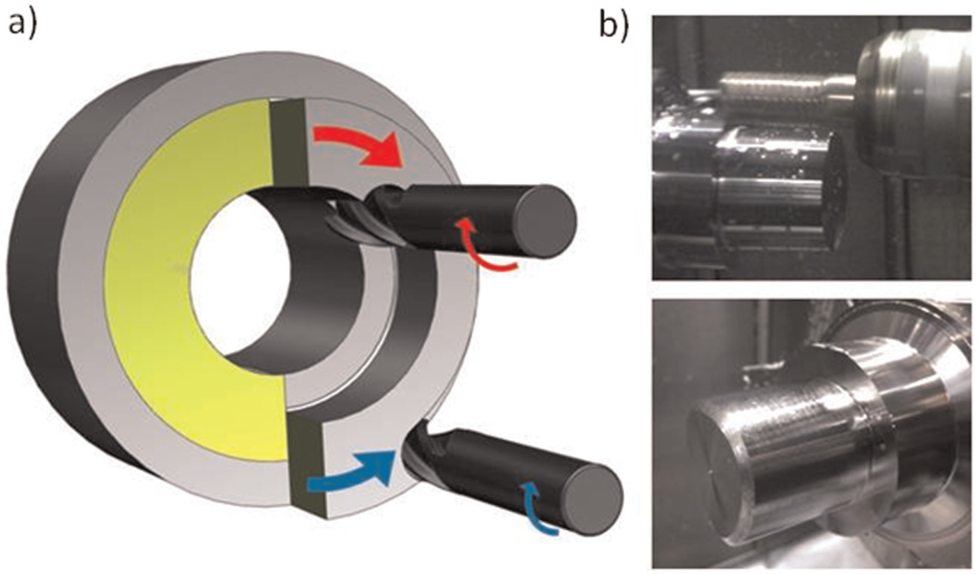
(a) Kinematics scheme of a coaxial turn-milling and (b) practical example for an elliptic section hub.
Some operation aspects can be highlighted: (a) by using appropriate tools, internal machining can be carried out without previous holes; (b) non-cylindrical surfaces can be machined, for example, flat faces are easily machined; (c) narrow channels can be produced and (d) the technique can produce external threads using thread mills. Finally, the principal drawback is the necessity of large tool overhangs for deep cavity milling, which penalize tool stiffness.
Orthogonal turn-milling
The process is named orthogonal when tool is perpendicular to part axis. This technique is only suitable for external milling. There are several advantages related to this technique:
Good results are obtained for thin-wall machining. Cutting forces are lower than those of turning, and therefore, lower deformation errors happen.
Shorter tools are allowed; the milling process becomes stable when chip removal rate is high.
If tool rotary speed is big enough, the quality of final surface is very good, even in comparison with the good finishing of grinding. 15
Chip evacuation is much easier, and cooling is enhanced avoiding problems caused by excessive temperatures. 16
Part rotational speed is very low with low centrifugal forces. In turning, high spindle speeds are always dangerous.
A variation in the orthogonal milling is when the milling tool is tangent to workpiece (Figure 2). This technique has inspired several investigation works whose objective was to analyse machining parameters for achieving a very good superficial roughness. In these cases, tools were finishing mills, usually integral carbide ones.17,18
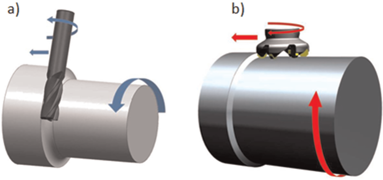
(a) Orthogonal turn-milling with entire tool and (b) orthogonal turn-milling with insert tool.
Orthogonal turn-milling operations can cause a characteristic crescent moon footprint on part surface. This effect is caused by the simultaneous rotation of tool and part. Axial feed direction also shows a peculiar geometric form, depending, in this case, on the tool geometry and the tool Y-axis compensation value, called Ew (mm). Thus, Figures 3 and 4 represent exaggerated cases. One of these extreme cases corresponds to Ew = 0% ∅ef, ∅ef (mm) being the effective diameter of the cutting tool. This spatial position of the tool generates a convex surface in the machined surface, as seen in Figure 3. This operation is recommended for slot finishing generating the fillet radius between the floor and the wall. This way, the cut is similar to a turning operation (ramping), where tool inserts machine with the lower edges, generating high axial forces.
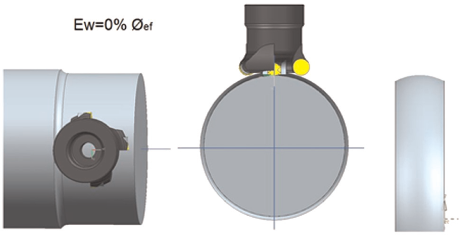
Extreme cutting case Ew = 0% ∅ef.
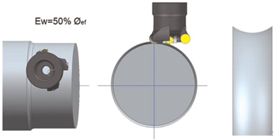
Extreme cutting case Ew = 50% ∅ef.
The other extreme case corresponds Ew = 50% ∅ef. This spatial position of the tool generates a concave surface (Figure 4). This displacement avoids the effect generated in the lower part of the tool and consequently cutting forces are reduced. This position avoids interference risks between the tool centre and the part whatever the axial depth is (ap).
Pinch machining
In general applications, once a part has gone through the roughing process, finishing turn-ball-end milling processes must be applied. In order to obtain low cutting forces during the machining of thin-feature parts, machines with two opposing turrets are a good choice. These machines allow pinch (or balanced) machining, where two tools cut simultaneously on either side of the workpiece. 19 Some CAM software packages such as ESPRIT® have introduced this technology. Pinch machining was used in turning, but recent developments in machine and CAM are expanding pinch machining to milling as well.
Simultaneously cutting with two tools is not only faster, but it does also cause balanced cutting forces. Balanced milling or turn-milling operations lead to faster cycle times. When two tools cut the same profile simultaneously, with one tool above the part axis and the other below, feed rate for each tool can be doubled without affecting tool load. Another technique is to start a cut with one tool, while the second tool waits until a fixed distance is reached. Then, the second tool follows the first in delay to perform a second cut at a different depth, performing two operations in the same pass.
On the other hand, deflection is a serious problem when slender or long workpieces are machined with a single tool. Simultaneously applying two tools on either side of the workpiece balances cutting forces to counteract deflection from uneven tool pressure.
Numerous operations can be performed using the so-called pinch machining concept (Figure 5). For example, balanced roughing that allows the feed rate to be doubled while maintaining the same cutter load. This is by far the fastest way to rough a profile. If the trailing tool waits until the leading tool reaches a user-defined distance before it starts cutting, both tools can cut at different depths to perform a rough and re-rough at the same time. The same concept can be applied to semi-finishing or finishing operations. In addition, inside- and outside-diameter turning is also possible if both operations are synchronized. Pinch grooving can also be performed if both grooving operations have been synchronized at the start of each plunge.
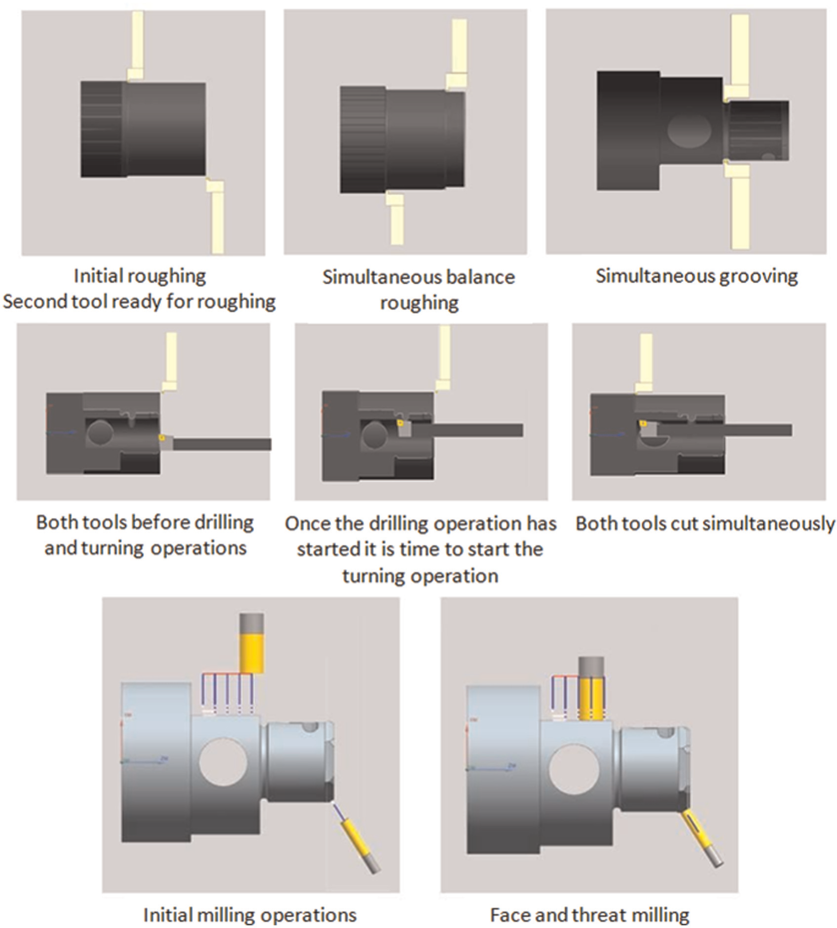
Pinch machining operations: turning and milling operations.
Pinch milling is much like pinch turning except that the operations use live milling tools in the upper and lower turrets (or spindles). Pinch milling and drilling are the most productive when both turrets allow off-centre Y-axis movement. However, even without a Y-axis, pinch slotting and drilling can easily be performed on the centre line.
The movements of the two milling tools must be synchronized by programming. The milling operations can be developed for the lower and upper turrets and then synchronized in the operation manager utility of the CAM software.
Turn-ball-end milling: five-axes pinch milling
Five-axes pinch milling (Figure 6) technology represents a challenge in CAM programming because the upper and lower milling tools follow different contouring tool paths that must be carefully coordinated to synchronize the axis motions. To carry out five-axes pinch milling strategies, a multitasking machine with B-axes head and a lower turret that supports live tooling is required. Having opposing spindles is also recommended. Spindles of multitasking machines provide the C-axis motion and provide balanced support at each end of the workpiece. This type of pinch milling is well suited for producing turbine blades since blades are typically long, thin and prone to deflection. When the blade is supported between opposing rotary spindles, the spindles can clamp and apply torque at both ends of the workpiece. Because the part can be held more rigidly and is subjected to far less deflection, allowable spindle load can be increased on both spindles. This configuration also permits the use of bull-nose end mills, which can take wider passes than ball-nose end mills without increasing cusp height. By keeping a bull-nose tool normal to the surface during simultaneous five-axes machining, the machine can maintain constant cutting speed. The result is faster metal removal and superior finish. Cutting with two tools lets workshops crank up feed rates and maximize throughput with aggressive turning techniques.
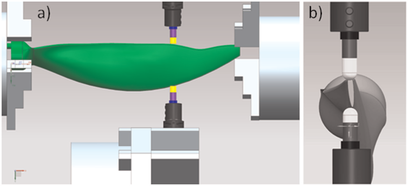
(a) Frontal view of a five-axes pinch milling propeller blade and (b) lateral view of a five-axes pinch milling propeller blade.
Five-axes pinch milling is only possible in very expensive multitasking machines, more oriented to special complex part machining than to high production of blades. Serial production is solved with a not-so-expensive machine asmultitasking machine. This is the case of the next strategy, the so-called off-centre milling.
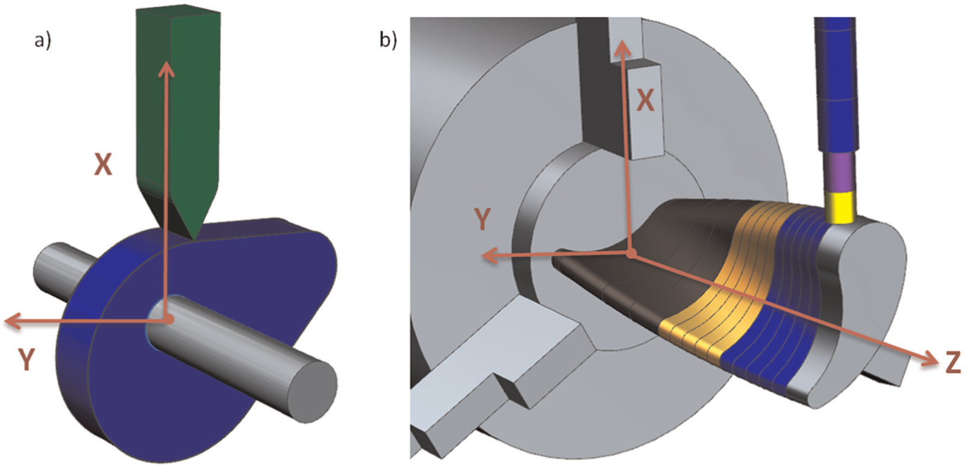
Off-centre milling: Y-axis mill-turn machining
For off-centre milling, a fourth or Y-axis must be added to a lathe, resulting in the so-called turning centre machines. A Y-axis adds a third linear axis to the turret, allowing rotary cutters to machine across the spindle–tailstock centre line. While maintaining the ability to index the part along the C rotational axis, Y-axis provides an additional direction of tool movement. Y-axis significantly increases productivity by allowing workshops to produce parts with geometrical features off the centre line. Y-axis programming lets user to use a lathe as if it was an indexable milling machine to program operations on the diameter or face of the part.
Thus, a Y-axis-equipped mill-turn centre can be thought of as two independent machine tools in one. First, there is a turning centre that operates exactly like any other two-axes lathe, and to that platform, a four-axes machining centre is added.
Nevertheless, from the mechanical point of view, the Y-axis programming operations could be compared to a cam and follower system (Figure 7), in which Y-axis would be the eccentricity of the follower with respect to the cam centre of rotation. Also, for blade manufacturing, in order to obtain an accurate motion follower, the profile of cam must be designed and machined precisely too. 20
Comparison of a (a) cam and follower system and a (b) Y-axis turn-milling operation.
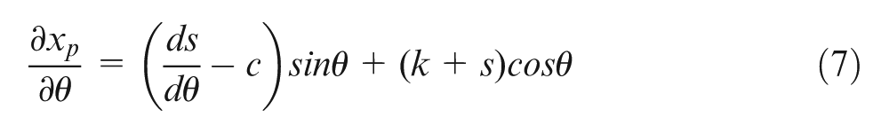
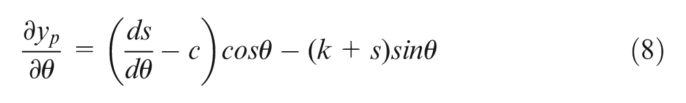
The variation in the follower eccentricity values could be compared to the different Y-axis values in the CNC program. On the other hand, the pressure angle for each cam angle in the cam and follower system (Figure 8) could also be compared to the tool machining angle with the part surface normal line. In both cases, good values for the angle between normal and workpiece (or cam) with the ball-end milling tool (or roller follower) must be kept within ±20 grades for a good function of the system. The milling tilt angle α (equation (1)) could be defined as
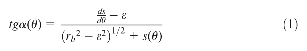
where rb is the minimum inscribed circle radius in a blade, ε is the eccentricity that is achieved by moving the turning centre Y-axis, and s(θ) is the equation of the blade surface. A special algorithm for CNC programming of the ball-end mill contouring of each blade’s traversal section was written. Making use of it, and input parameters being the final blade surface, desired tool tilt angle and radial width of cut, tool paths are defined along blade Z-axis.
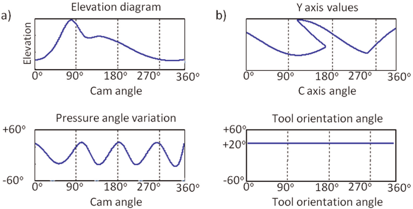
Diagram comparison between a (a) cam and follower system and a (b) Y-axis turn-milling operation.
Therefore, in the blade machining case, the tool orientation angle is desired to be always 20° (15° to 25° are good choices for ball-end mills). So, two possibilities can be applied starting from the blade surface defined in the computer-aided design (CAD).
In finishing operations, the main outcome to achieve is a smoother surface, which is measured by mean of the roughness. Other aspects such as cutting forces that are related with tool deflection or tool wear are not the drivers of the toolpath programming. Anyway, tool deflection can be reduced by applying a tool-axis orientation of approximately 15° to 25°, as it is stated in López de Lacalle et al. 21 and recorded and tested in López de Lacalle et al. 22 These values prevent from cutting with the ball-end mill tip (where the cutting speed is zero), with a good orientation of forces, reducing the force component perpendicular to the tool-axis and surface.
Method 1: based on considering the blade as a cam surface keeping pressure angle constant
For defining an eccentric roller cam, the cam surface is obtained by the theory of envelope curves, using a generic position of the cam-roller. Thus, looking at Figure 9, the centre of the roller is given by


where k is a geometrical relation of basic parameters
The roller generic equation is then
Deriving this equation with respect to the generic angle
The derivatives are as follows
Finally, the cam profile is defined as
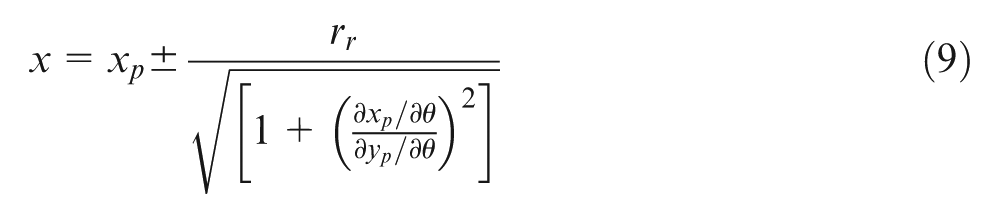
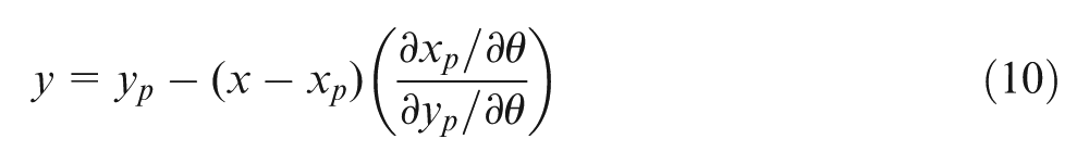
However, only the negative sign is interesting in the equivalency of cams to blades.
The first method for calculating the CNC program, by equivalency to the CAM case.
Therefore, the developed algorithm acts as follows for each sagittal section of the blade:
A point on the blade surface (A) is chosen, using a discretizing step chosen by user.
The maximum inscribed circle (rb) is defined for the blade section in which a point A is located.
The centre of the roller (ball end of the milling tool) tangent to the blade surface for the chosen point is defined. This is the position of the tool centre point (TCP).
The pressure angle is determined by means of equation (1), resulting in the Y-axis position or the eccentricity (ε). The X position is obtained by Pythagoras using the value of the diagonal d and the just calculated eccentricity.
Applying this algorithm for all the blade surface points, both Y-axis and X-axis are obtained, keeping pressure angle constant along all control points.
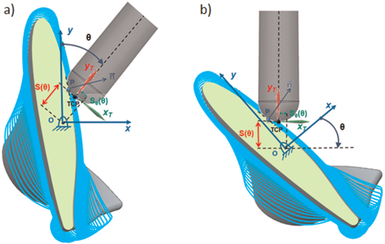
Method 2: based on the use of CAM for milling operations and coordinates change between relative movements in the turning centre
Most CAM softwares are able to define the TCP position and the tool-axis angle in order to keep a contact angle with the surface normal at each control point. However, while the workpiece is quiet, it is the tool that changes position and orientation.
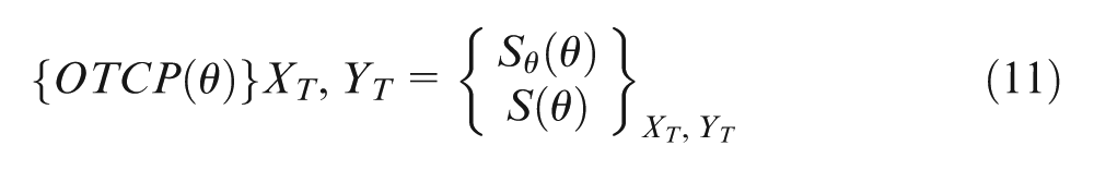
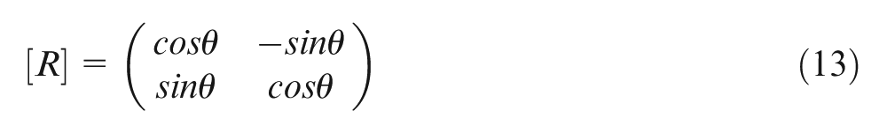
An inverse kinematic transformation must be applied for defining the real movement in the turning centre. For that purpose, two reference systems are defined: as it can be seen in Figure 10, one is associated with the blade (X, Y), while the other is defined on tool (XT, YT). The location vector OTCP(θ) (equation (12)), known in the tool reference, is transformed to X, Y, and a rotation [R] (equation (13)) must be applied

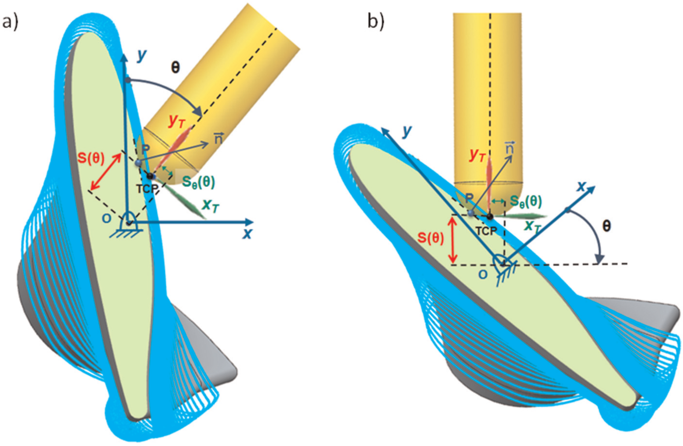
(a) Process definition at the CAM stage; (b) transformation to the turning centre axes.
Experimental tests
The test part was carried out in a turn-mill machining centre TC25BTY from CMZ Machinery with a NC GE Fanuc Series 31i-model A. Machine maximum strokes are X– 315 mm; Y– 80/60 mm; C– 0° to 360°.
The first test part corresponds to a warped geometry where three different strategies were tested for the finishing operations. Workpiece raw material was aluminium 7075-T6. The roughing process corresponded to a three-axes cavity mill strategy whose objective was to obtain a final geometry part close to the drawing one. On the other hand, helical strategies were chosen for semi-finishing operations. For finishing, different strategies were tested: radial helical strategies, radial (X-level) zig-zag helical strategies and longitudinal (Z-level) zig-zag strategies. At the same time, different angle positions (15°, 20° and 25°) were tested for the finishing operations (see Figure 11).
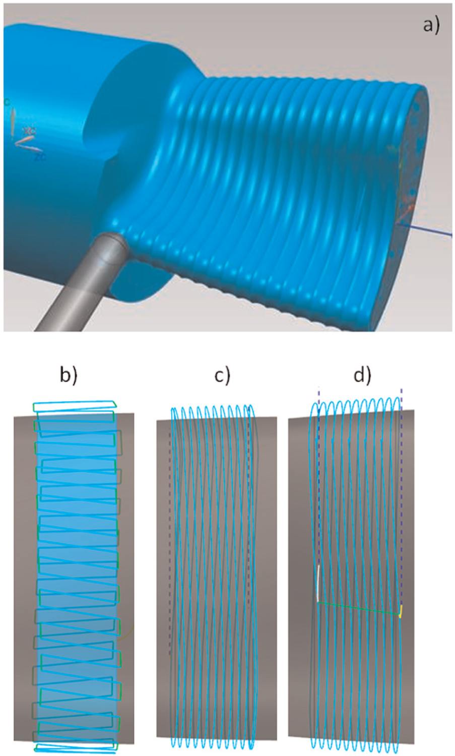
(a) Test part machining simulation, (b) longitudinal zig-zag strategies, (c) helical strategies and (d) ‘helical zig-zag’ strategies.
Regarding nomenclature, according to the machine reference system and machining direction, helical strategies could be defined as ‘Y-level’ strategies because machining direction corresponds to the Y-axis, the Z-axis being the one with less changing values (providing in this case the radial width of cut). On the contrary, longitudinal zig-zag strategies could be defined as ‘Z-level’ strategies because in this case, machining direction corresponds to the machine Z-axis; in this case, the Y-axis being the one with less changing values (giving the radial width of cut). Other machines inside the multitasking group could have different configurations, and this is not a less important issue because machine axes inertias and movements can have a direct influence on blade precision, as it is discussed in the following section.
Figure 12 shows the different machined areas in the test part. Thus, zone 1 represents the longitudinal zig-zag strategies for the different tool-axis angles tested: 15°, 20° and 25°. Zone 2 represents radial zig-zag helical strategies also tested for the different tool angles, and zone 3 represents radial zig-zag strategies.
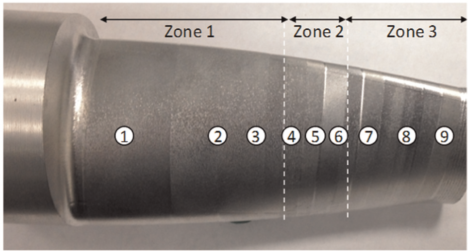
Test part geometry.
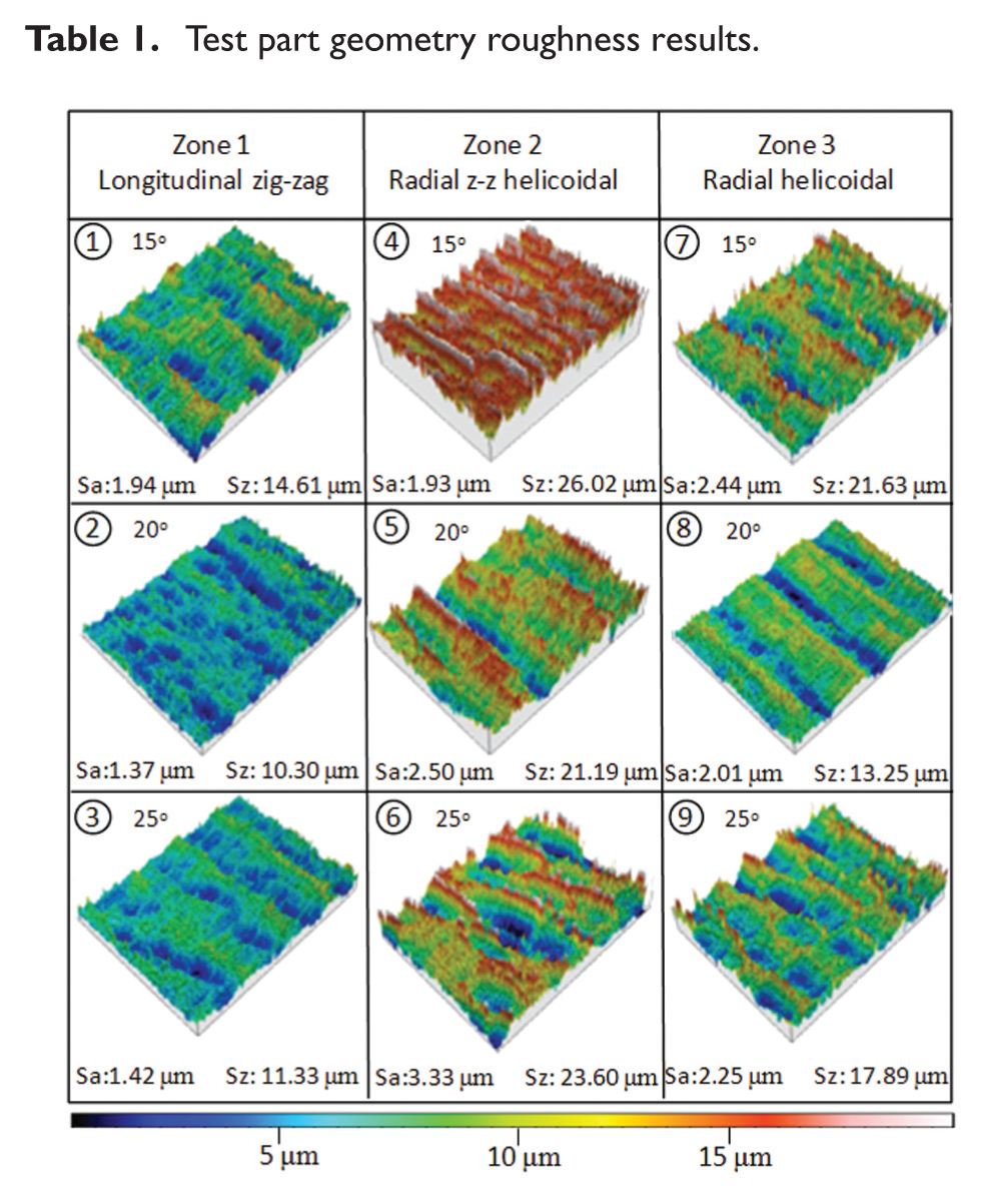
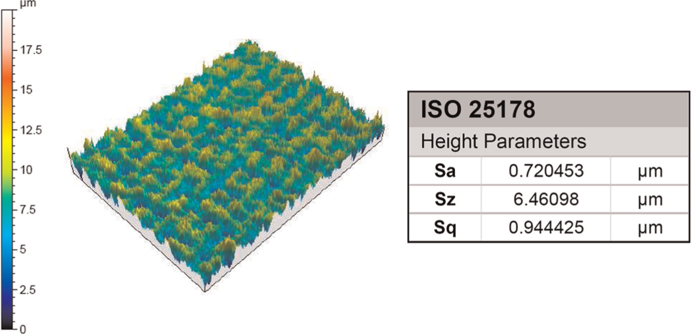
As shown in Table 1, where roughness measurements are gathered, using a Leica DCM high-resolution device, the best surface finish was obtained for the longitudinal zig-zag strategies (zone 1) and 20° tool angle position. It can also be observed that radial helical strategy results were better than those of the radial zig-zag helical strategy. Also, for the cam follower where there is an optimal pressure angle between −30° and 30°, in machining there is also an optimal tool-axis machining angle that in this case corresponds to 20°.
Test part geometry roughness results.
Finally, machined part was measured making use of an optical scanner (ATOS from GOM®), a blue light scanner. After the measurement, a cloud of points was obtained and compared to the original CAD. As seen in Figure 13, zone 1 strategies (i.e. longitudinal zig-zag strategies) matched with the initial CAD geometry within a precision of 20 µm. On the other hand, in zones 2 and 3, which correspond to helical strategies, there was a deviation of nearly 200 and 400 µm. Therefore, and as it has been previously mentioned, it can be concluded that longitudinal zig-zag strategies are the most appropriate ones for this application.
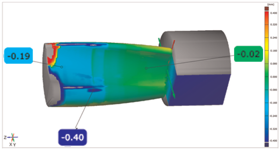
Test part measurement results with the ATOS GOM.
The zone 1 precision level would be enough for general turbomachinery components because working conditions caused bigger deformations or thermal distortions.
Blade case study
A real case study based on a propeller blade geometry of 150mm long was machined and three parts were machined for repeatability purposes. Regarding strategies, initially a roughing turn-milling strategy was carried out to obtain a blade pre-shape, and afterwards, the semi-finishing operation was carried out for blade contouring. Finally, the blade was turn-ball-end milled for finishing. Also in the previous test part case, different strategies were studied for the blade finishing. They correspond to helical strategy (Y-level) and longitudinal (Z-level) zig-zag strategy (Figures 14 and 15) where milling parameters are also shown. In both cases, the tool orientation angle was 20° because it was shown the best in previous test part.
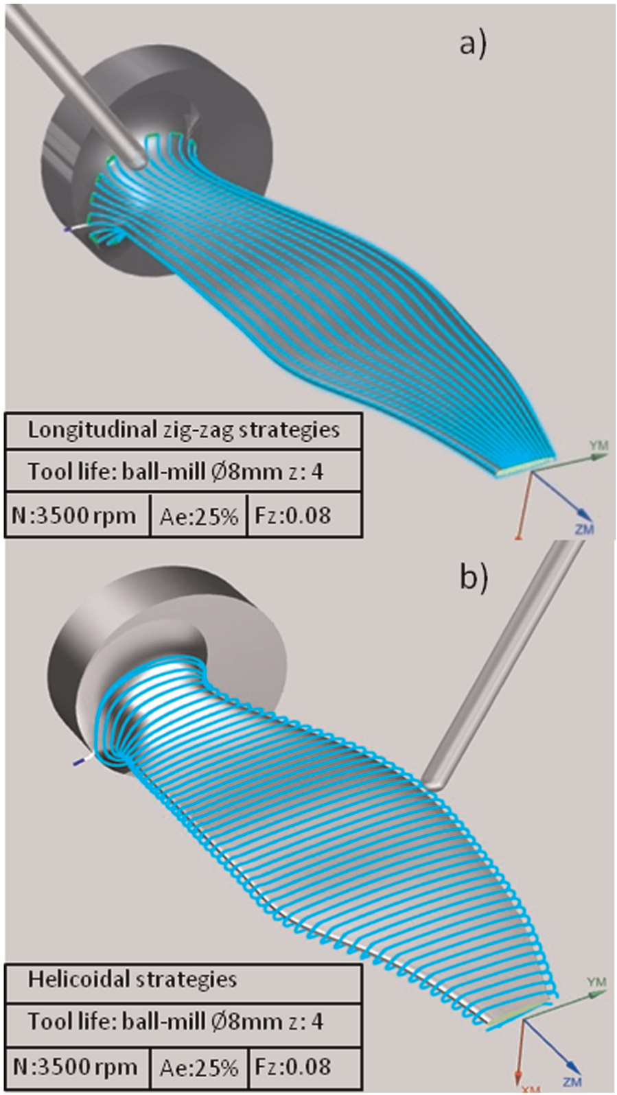
Propeller test part geometry: (a) longitudinal zig-zag strategy and (b) helical strategy.
(a) Blade semi-finishing and (b) blade finishing.
Helical strategy was similar to helical zig-zag behaviour, the difference is that helical strategy maintains up-milling machining along the whole operation, whereas for helical zig-zag there is a continuous change between up-milling and down-milling cases. Therefore, helical strategies were chosen for the blade semi-finishing operation instead of helical zig-zag.
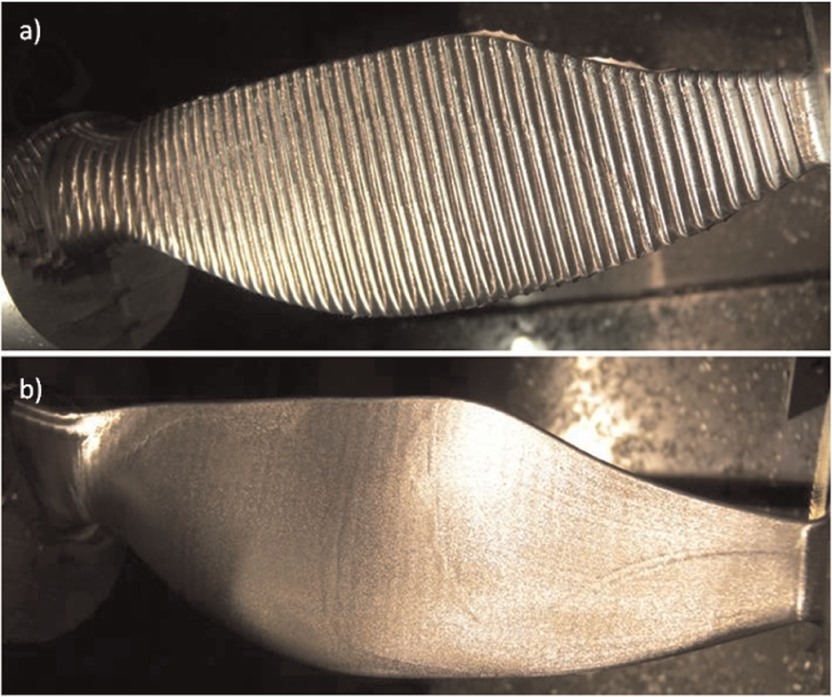
On the contrary, as seen for the test part, the best surface finishing quality (Figure 16) was obtained by longitudinal zig-zag strategies (Z-level) and 20° tool orientation angles, and hence, this strategy was chosen for the finishing operations.
Blade roughness.
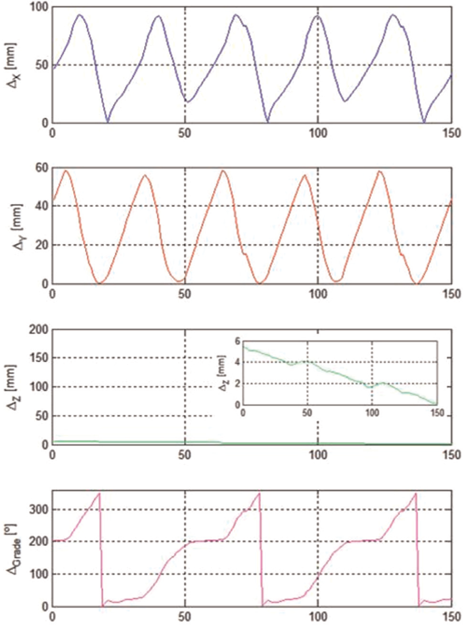
According to the reference system orientation and the machining direction, it can be concluded that helical strategies could be defined as ‘Y-level’ strategies because the machining directions correspond to the Y-axis direction, the Z-axis being the one with less changing values (providing width of cut). On the contrary, longitudinal zig-zag strategies could be defined as ‘Z-level’ strategies because in this case, the machining strategies correspond to the Z-axis direction and Y-axis being the one with less changing values (the radial width of cut).
For this reason, if there would be a comparison (Figures 17 and 18) between longitudinal zig-zag strategies (Z-level strategy) and helical strategies (Y-level strategy), it can be concluded that C-axis movements (Δgrade) are smaller for the longitudinal zig-zag strategy (Z-level). The movements suffered by X-axis (Δx) and Y-axis (Δy) are also smaller, so lower inertias are associated with the longitudinal zig-zag strategy than with the helical strategy. Thus, it can be stated that longitudinal zig-zag strategies (Z-level strategies) are smoother than helical zig-zag strategies (Y-level strategies). The main conclusion is that for this type of pieces, long, thin and with two faces, well-defined, longitudinal zig-zag toolpath programming is highly recommended.
Helical strategy (Y-level strategy).
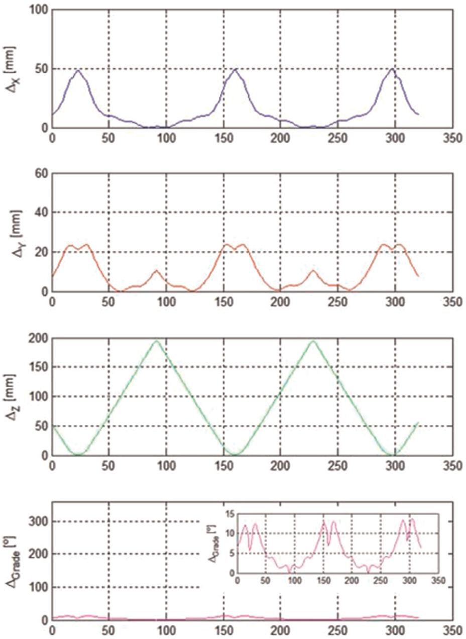
Longitudinal zig-zag strategy (Z-level strategy).
In the mould industry, Z-level toolpath programming in which the stock allowance is left towards the slope is the prime choice when a free-form surface is milled because forces are approximately constant along tool trajectories. Doing that cutting forces change when a new step is performed for removing another Z-level path. Conversely, in the blade case, the movements in the C-rotary axis and in the Y-axis are due to the radial width of cut, usually moving without cutting. Therefore, machine axes movements are less and shorter than those in the forward or downward milling cases, which imply all time both C-axis and Y-axis movements. The latter is more complicated to control and represents a dynamic excitation for the process. In the work by López de Lacalle et al., 23 all inclined plane milling cases were studied, obtaining very good results with Z-level strategies.
In the latter case, blades were also measured with the ATOS GOM system in order to determine whether the blade matched the geometric tolerances required. As seen in Figure 19, where the final results are shown, the final blade matched with the initial CAD geometry within a precision of 40 µm, this value being the mean one of the three blades machined. One practical conclusion is that optical measurement is suitable for these applications, and this kind of measurement systems gives enough resolution for turbomachinery component manufacturing.
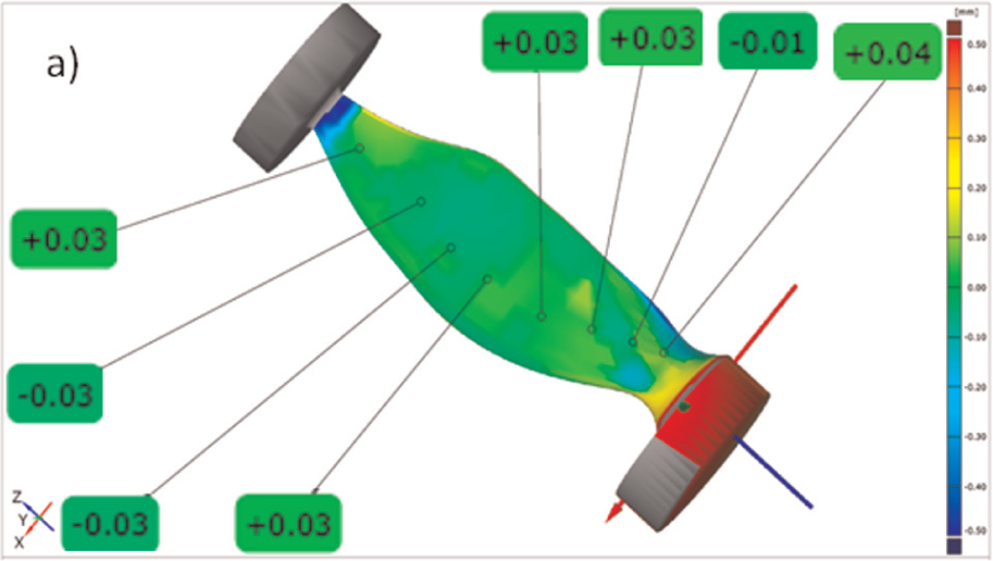
Blade measurement results with ATOS GOM.
Conclusion
In this work, turn-milling strategies for multitasking machines were studied. Orthogonal turn-milling, coaxial turn-milling and pinch-milling operations were described as suitable for the manufacturing of blades or other complex forms. In addition, Y-axis turn-milling operations are also studied from two different points of view: one is based on considering the blade as a cam surface and the other one is based on CAM. The methodology to follow in both cases is also detailed.
On the other hand, a test part whose geometry corresponds to a wrapped feature was machined using different strategies. In this case, longitudinal zig-zag strategy with a 20° tool angle resulted in the best part quality. Finally, the obtained results were applied to a real propeller blade case, applying Z-level zig-zag and reaching good metrological results.
In short, turn-milling operations represent an option to be considered for complex parts such as blades. For this purpose, the required machine is in the group of multitasking new ones; however, a turning centre is also suitable for this application. A turning centre is a lathe with additional C-axis, with Y-axis and living tools in the turret. In both multitasking and turning centres, the key for achieving good results is the programming of CNC for keeping tool tip and axis in the best orientation (20°) with respect to the target surface.
The main conclusion of this work is that for pieces that are characterized for being long, thin and with two faces (such as blades), longitudinal zig-zag toolpath programming is highly recommended. Configuration of machine axes is a key factor for achieving good results. This operation can be applied in turning centres with Y-axis, C-axis and live milling tools or in new multitasking machines. The former is a common machine in a lot of small companies, whereas the latter is an expensive machine.
Footnotes
Declaration of conflicting interests
The authors declare that there is no conflict of interest.
Funding
This study received financial support from the Department of Education, Universities and Research of the Basque Government and from the Department of Industry, Innovation, Trade and Tourism of the Basque Government (through Etortek proFUTURE project). This study was also supported by the Ministry of Innovation of Spain via project INNPACTO Desafio and received funds of the UPV/EHU (UFI 11/29).