
Abstract
The electrochemical discharge machining is a combination of electrochemical machining and electrical discharge machining. The machining is achieved by chemical etching effect and melting of workpiece material due to electrical discharges. This process is used for a variety of nonconductive materials (glass, quartz, ceramic, Pyrex and so on) for the purpose of micromachining and specially for micro electro mechanical system applications. This article presents a comprehensive review of recent developments on tool electrode process parameters, which have resulted in enhanced efficiency and accuracy of the machining process. The tool electrode process parameters are shape, size, roughness, insulation and motion of tool and so on. These process parameters affect the process performance in terms of material removal rate, surface quality and dimensional accuracy of micromachined products. For example, spherical tool geometry provides five times higher material removal rate as compared to cylindrical tool geometry. The impact of electrochemical discharge machining process parameters associated with tool electrode is also discussed. A summary of review and proposed research directions is presented in this article.
Introduction
The electrochemical discharge machining (ECDM) process is a combination of electrochemical machining (ECM) and electrical discharge machining (EDM) processes. This process has very good potential in the area of micromachining nonconductive hard and brittle materials such as ceramic, glass, quartz and Pyrex. ECDM process involves melting and chemical etching of the workpiece due to high electrical energy discharged on the tip of the electrode during electrolysis. 1 The literature reveals that combined metal removal rate in ECDM can be 5 to 50 times over EDM and ECM with decreased electrode tool wear. 2 –5 ECDM process requires two electrodes. One is the tool electrode, which is used to produce desired machined shape, and the other is the counter electrode or auxiliary electrode made as anode.
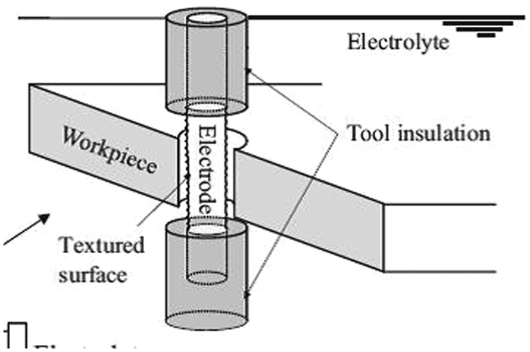
The workpiece and counter electrode (anode) are immersed in an electrolyte solution (typically sodium hydroxide or potassium hydroxide). The tool electrode (cathode) is kept 2–3 mm dipped in the electrolyte. Counter electrode or anode is a large size dummy electrode in general, which is kept at a distance of about 25–50 mm away from the tool electrode. Electrolysis starts when a voltage is supplied by a direct current (DC) power source between the tool electrode and counter electrode. A schematic of the process is shown in Figure 1.
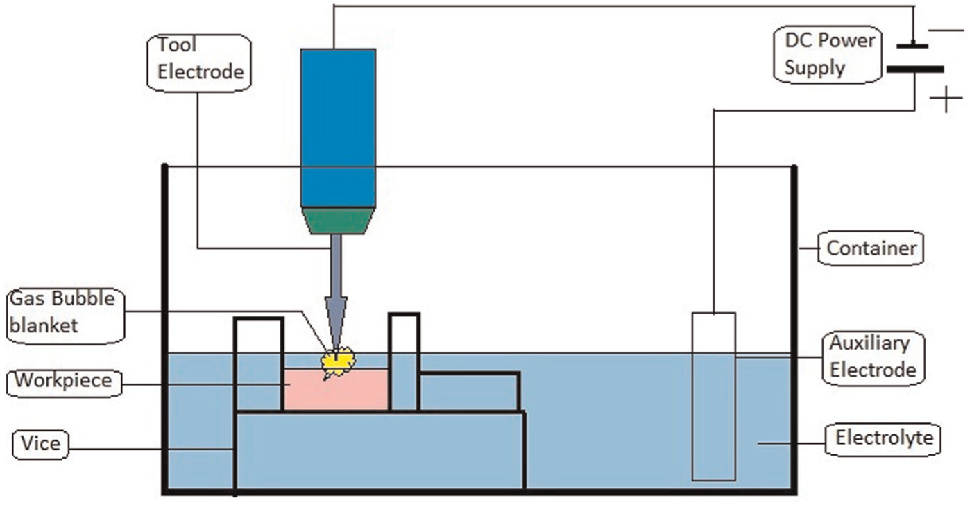
Schematic of ECDM Process.
Surface area of the tool electrode submerged in the electrolyte is kept very small compared to counter electrode (anode). This results in high current density at the cathode. Rapid production of hydrogen gas bubbles takes place at the cathode due to ohmic heating of the electrolyte solution. Surrounding electrolyte insulates the immersed tool electrode (blanketing effect) 6 by a gas film due to bubble coalescence. Gas film plays a key role in machining during ECDM. A stable and dense gas film conditions the machining process. A stable gas film can be achieved by either low terminal voltage with spark generation or periodic formation of the gas film. An unstable gas film results in fluctuating spark and results in nonrepeatable machining. 7
Spark action takes place between the tool and the workpiece when the current density of the tool exceeds the critical value (typically around 1 A) and applied voltage also becomes more than the critical voltage (approximate 25 V). The critical value of current and voltage depends on the geometric shape of the tool point and concentration of the used electrolyte. 7 As the workpiece lies in close proximity (typically within 20 µm) to the tool electrode, material removal takes place by melting and etching of the workpiece. 8 This material removal process mechanism is known as ECDM.
ECDM process has the limitations such as surface defects due to localized overheating, which requires a suitable arrangement of intermittent cooling such as pulse power supply. Low material removal rate (MRR), low depth of penetration, overcut and taper in the hole are major problems in the ECDM. These may be due to lack of flow of electrolyte at tool point during machining. However, these problems can be minimized by a proper design of tool point of tool electrode.
Tool electrode may be given a suitable movement in order to get better results of machining such as rotation. Tools are also vibrated ultrasonically to give linear movement. These tool movements result in reduction of taper, overcut and better surface quality of sidewalls.
Tool and its significance
The tool electrode has a significant role in the machining. The lesser area of the tool cross section is used for achieving higher current densities. Tools with pointed ends are preferred geometries as they concentrate sparking action at the tool point. This results in better machining performances with quality surface of the workpiece.
The size of the counter electrode is kept as large as possible and material of this electrode must not react with the electrolyte used. The current density being less on counter electrode limits its anodic dissolution. Counter electrode should be shaped in such a way that distance between electrodes be constant while machining. A circular hollow pipe or ring can be used as anode surrounding the tool electrode. Such type of electrode can maintain a constant inter electrode resistance. This resistance should be reduced in order to minimize the time for formation of gas film as much as possible.
Materials for both electrodes should be properly selected. The tool electrode material should have the following properties:
It should be rigid as possible in order to resist bending or misalignment during machining.
The material should be chemically inert to the electrolyte used.
Materials have excellent corrosion resistance and good wear resistance.
The electrodes are made of stainless steel or nickel and preferred because these materials have excellent corrosion resistance, chemical resistance to electrolytes and minimum tool wear. 9 Tool wear is negligible in ECDM, which occurs due to chemical etching and anodic dissolution. The spark activity at the tool tip may be a cause of some tool wear. No significant tool wear was observed and has never been quantified. The same tool electrode (stainless steel) can be used frequently. Fabrication of precise shape and size of tool electrodes is a difficult task. However, wire electrical discharge grinding (WEDG) is possible solution and an excellent and flexible method for micro fabrications of tool electrode. 10 Anodic etching of tungsten is also another method for tool fabrication. 11
Physical features of the tool electrode such as geometry, rotation and roughness greatly influence efficiency and accuracy of the ECDM process. The surface roughness of the tool is an index of quality of gas film produced during electrolysis. This influences thickness, stability of the gas film and power supply requirement for spark action also. Geometry of the cathode tip is a measure of dimensional accuracy of the machining structure produced by ECDM.
Hence, tool design or configuration is important for ECDM process for improving machining efficiency and accuracy. This article presents a review on different types of physical features of tool electrode, which have been used in order to improve the machining performance by various researchers.
Tool electrode process parameters
Process parameters are defined as all those ECDM process variables whose variation affects measurable outputs (process responses). A particular type of variation in the physical feature of a tool, which can be observed and whose value influences more or less to the machining performance in terms of MRR, surface quality and dimensional accuracy, can be termed as tool electrode process parameters. All those process parameters, which cannot be covered in electrical and chemical process parameters, are classified as tool electrode process parameters in this article. Following are the different types of tool electrode process parameters:
Shape or geometry of tool;
Size or dimensions of tool;
Surface roughness of tool;
Material of tool;
Rotation speed of tool;
Machining time;
Immersion depth of tool.
The developments of these process parameters are classified into four groups due to the reason that some parameters and their impact on machining performance are similar in nature.
Classification of tool electrode process parameters
Tool electrode process parameters, which are interrelated to each other and similar in physical nature, are classified into one group. Shape, size, geometry and dimensions are interrelated features; therefore, these may be considered in one group and termed as geometry-based process parameters.
Surface roughness of tool materials may vary due to their different crystal structures in spite of the same manufacturing process. Hence, surface roughness and material of the tool are combined in one group, which are referred in subsequent sections as surface roughness–based process parameter.
The motion (rotary or linear motion) of the tool and immersion depth of tool are considered in single group and referred as tool motion–based process parameters. The last group is a general group, in which all those features of the tool covered, which are not considered in above three groups such as machining time.
Recent developments in tool electrode process parameters and their impact in ECDM
This section gives a review of recent studies of various process parameters classified as above in four groups and their impact on machining performance during ECDM.
Tool geometry–based developments
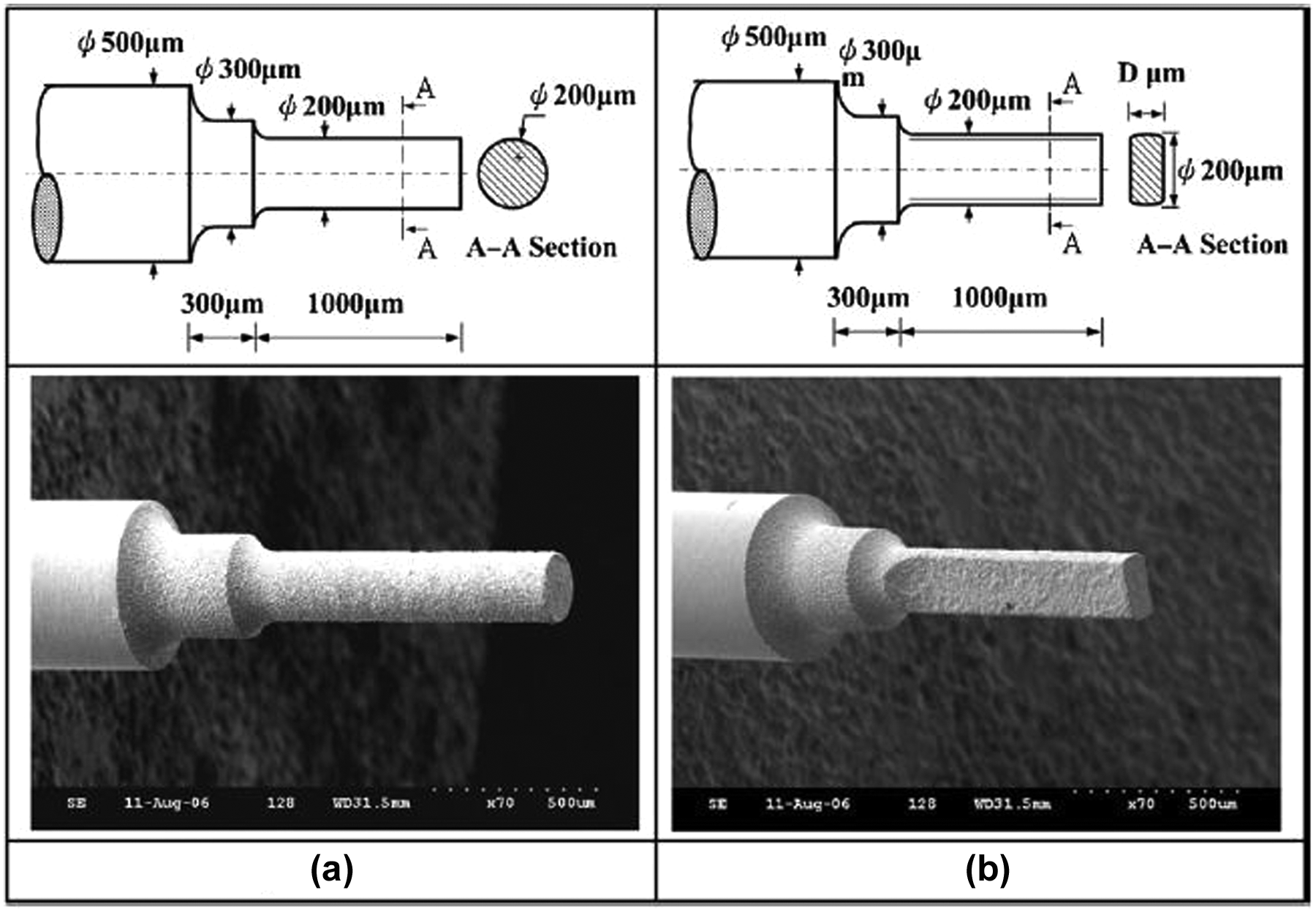
Yang et al. 1 investigated that a spherical end tool electrode (sphere of 150 µm diameter) takes 83% less time in machining a 500 µm depth through hole and hole entrance diameter is reduced by 65% as compared to simple cylindrical tool (100 µm diameter). This happens because the curve surface of the spherical tool decreases the contact area between the workpiece and electrode, which facilitates the flow of electrolyte up to the electrode end and develops the gas film at a faster rate. Curve surface decreases excessive concentration of current density, which results in more uniform speed of bubble formation and increases the discharge frequency. Thus such type of tool electrode drills the micro holes efficiently with improved shape accuracy and machining performance. Figure 2 shows the geometry of the micro tool and Figure 3 shows the impact of tool shape on hole entrance diameter used in machining.
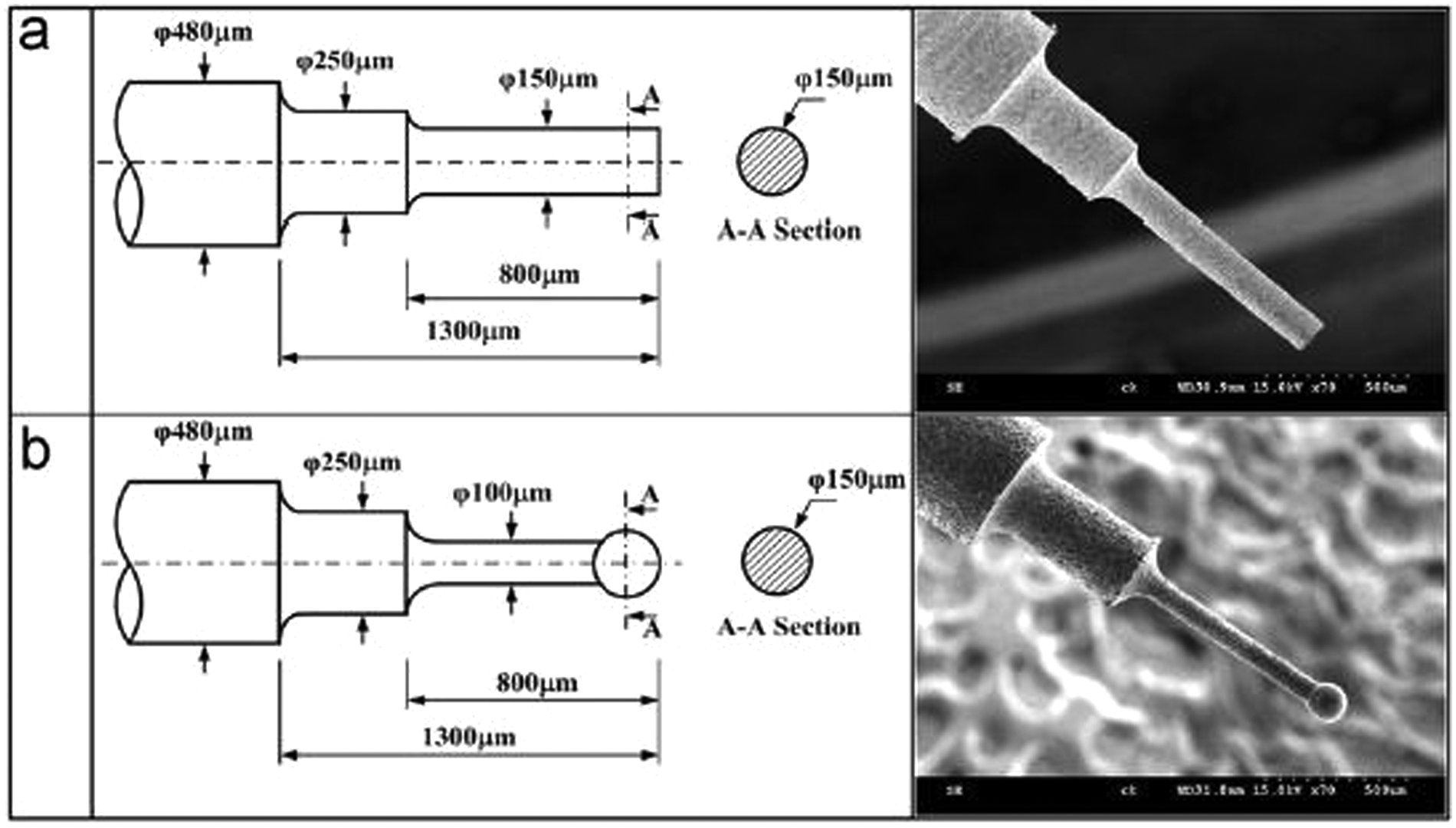
Tool electrode’s dimensions (µm): (a) cylindrical tool electrode and (b) spherical tool electrode (based on Yang et al. 1 ).
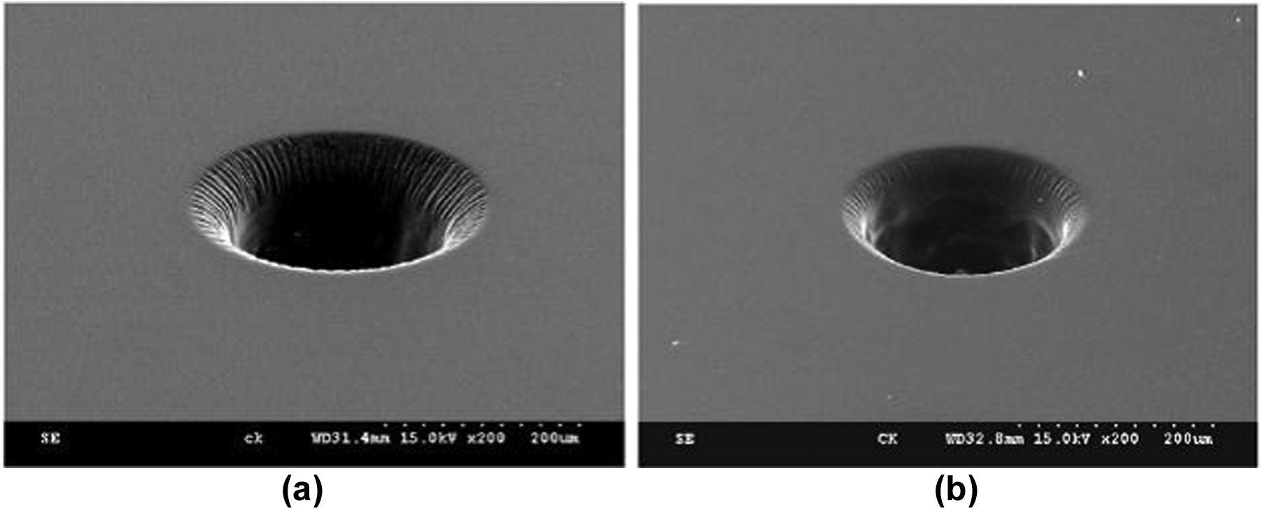
SEM images of micro holes machined by (a) cylindrical tool electrode and (b) spherical tool electrode (based on Yang et al. 1 ).
Cheng et al. 12 investigated that flat sidewall tool as shown in Figure 4 improves the quality of gas film while the drilling process in comparison to cylindrical tool. This results in increase in machining efficiency and accuracy.
Tools electrodes of different geometrical configurations (based on Cheng et al. 12 ).
The quality of gas film is found dense and stable in transition voltage. This transition voltage refers at specific levels above critical voltage. Gas film quality influences the workpiece geometric accuracy and surface roughness. Machined contours and current signals were taken as gas film quality indexes. Increase in electrolyte concentration increases the rate of electrolysis, which results in lower transition voltage with improved chemical etching and better surface finish.
Han et al. 13 studied the effect of using partially side insulated tool electrode as shown in Figure 5 in micromachining of micro channels. Investigations show that such kind of tool decreases the stray electrolysis, minimizes the fluctuation of current peak values and increases the discharge current uniformity of ECDM process. The above phenomenon results in better geometrical accuracy on the surface of micro channels.
Side insulated tool electrode (based on Han et al. 13 ).
Figure 6 shows the geometry of gas film formed on cylindrical tool electrode, which is not uniform, and hydrogen gas bubbles are unable to integrate in upper part of the tool point. Side insulated tool electrode depicts a stable large gas bubble, which covers the tool point completely. Film thickness of this gas bubble is also constant due to stable spark activity. Figure 7 shows the scanning electron microscopy (SEM) image of micro channel machined by above two types of electrodes. Machining by conventional tool electrode lacks the uniformity in width and surface roughness as compared to side insulated tool electrode.
Difference in geometric shape of the gas film produced by (a) conventional electrode and (b) side insulated electrode (based on Han et al. 13 ).
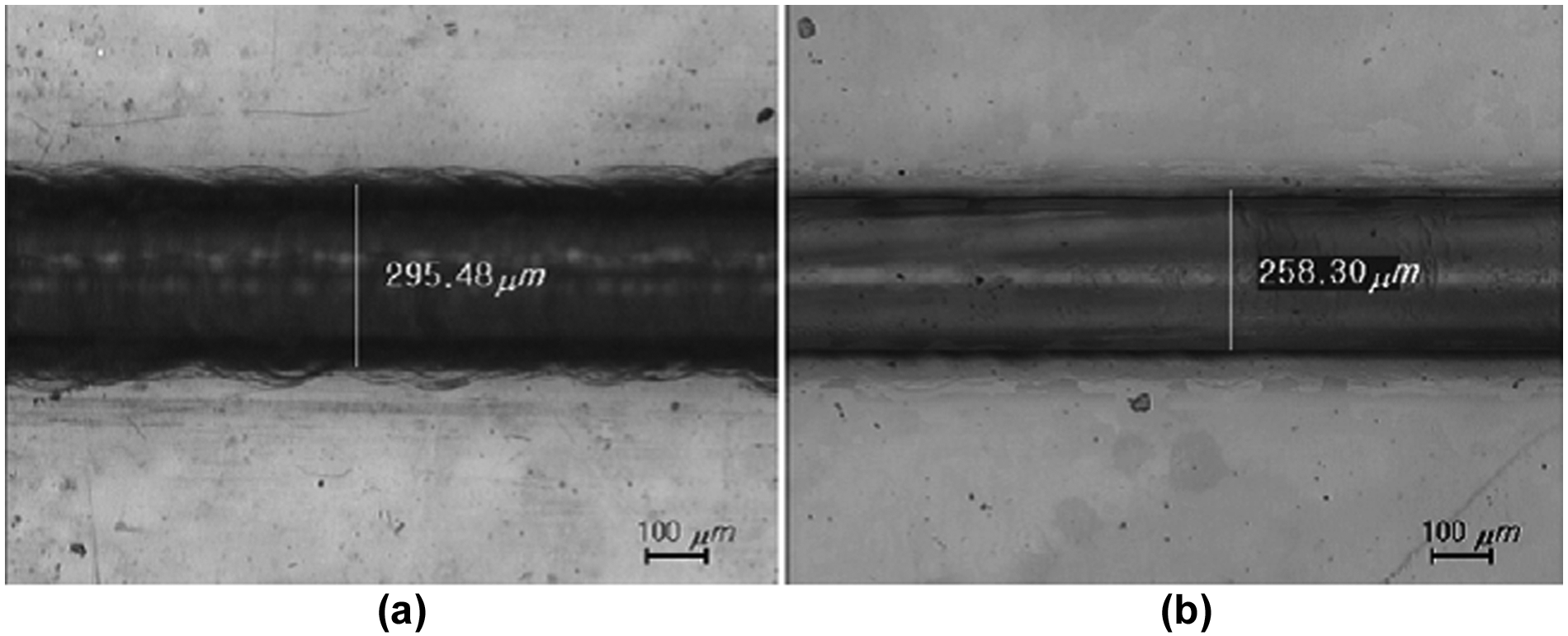
Micro channel fabrication using (a) conventional electrode and (b) side insulated electrode (based on Han et al. 13 ).
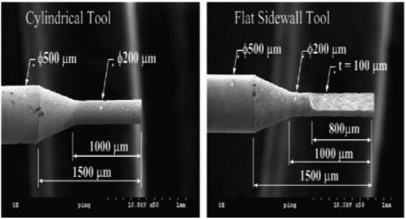
Zheng et al. 14 fabricated a new type of tool, which has flat sidewalls and a flat front, as shown in Figure 8. These sidewalls decrease the discharge around the tool, which results in a decrease in hole taper and increases the machining accuracy. Figure 9 represents a schematic of discharge-affected zone by circular tool and flat front tool in the Pyrex glass. The optimal values of area of cross section of the tool (front flat) and rectangular pulse voltage enhance the machining accuracy. A peak value of the tool rotational rate was observed, which gives the improved process performance with minimum overcut.
Different sidewalls of the tool (Zheng et al. 14 ): (a) cylindrical tool and (b) flat sidewall–flat front tool.
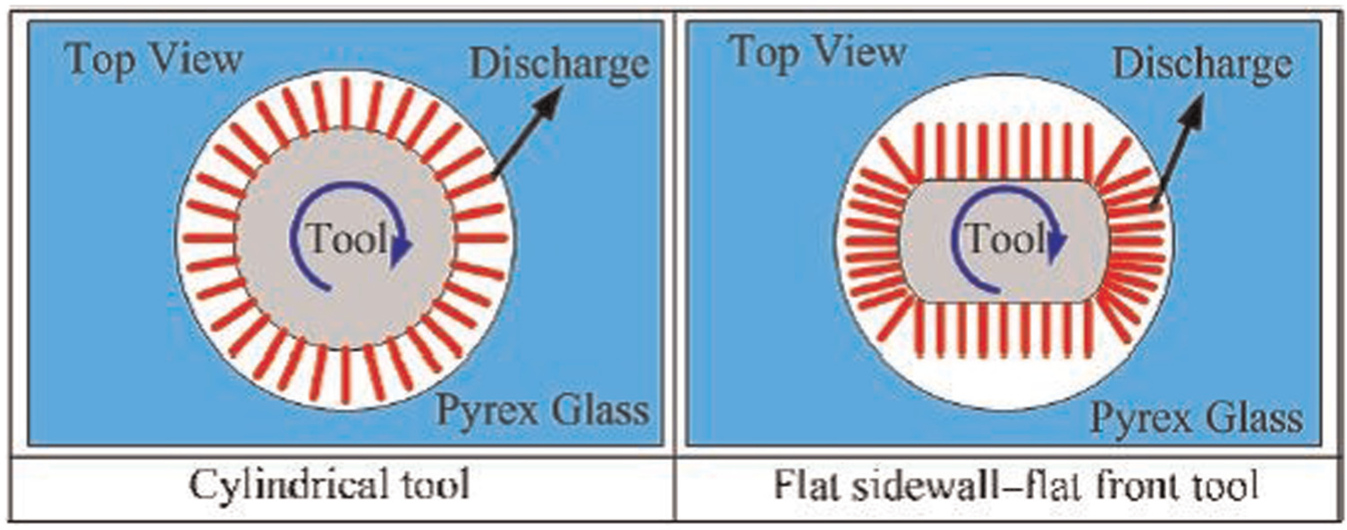
Schematic of the discharge-affected zone for different tool cross sections (Zheng et al. 14 ).
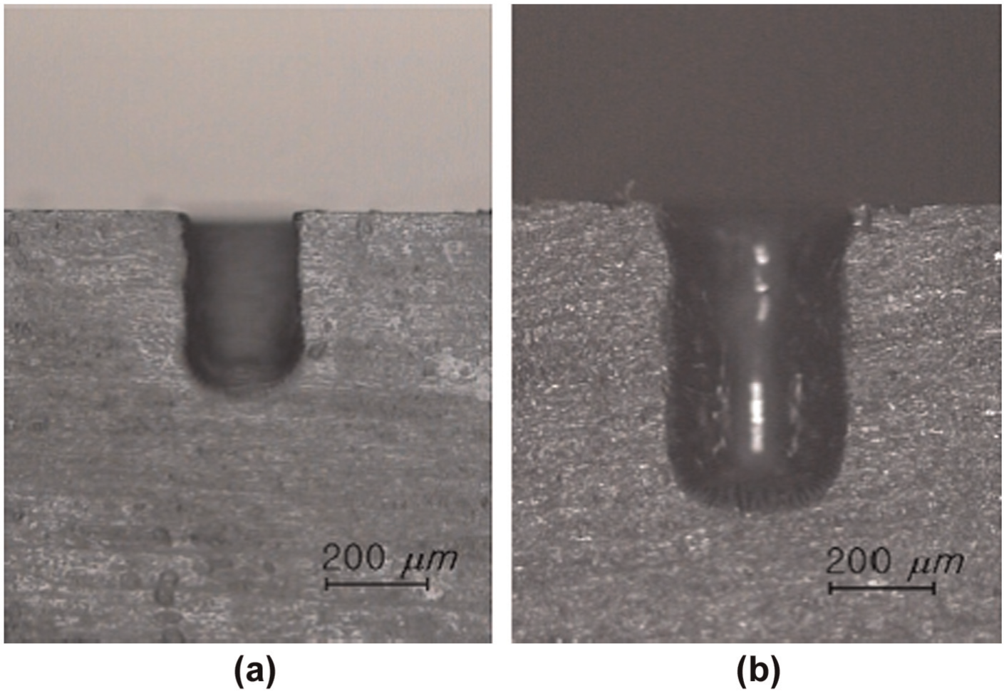
Figure 10 represents the micrograph of the micro hole in which taper of the hole is clearly visible. This taper is reduced using a flat sidewall and flat front tool.
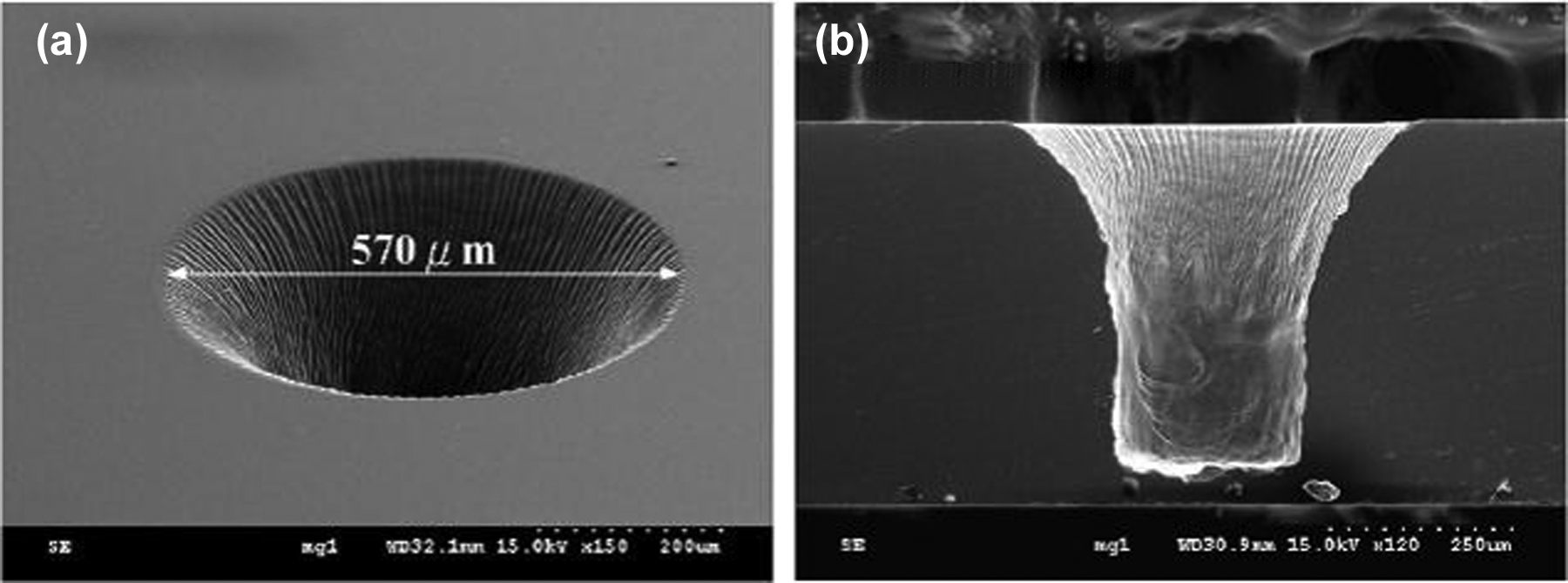
Micrograph of the micro hole in Pyrex glass machined from cylindrical tool (ϕ200 µm) with 500 r/min of tool and 40 V rectified DC voltage (Zheng et al. 14 ): (a) top view and (b) side view.
Tool motion–based developments
Han et al. 15 investigated that electrolyte with ultrasonic vibration causes the adequate flow of electrolyte between the tool and workpiece. The acoustic pressure distribution developed due to ultrasonic energy modifies the bubble layer (Figure 11). Thus, uniform spark is generated (Figure 12). Consequently machining depth increases during hole drilling in ECDM process.
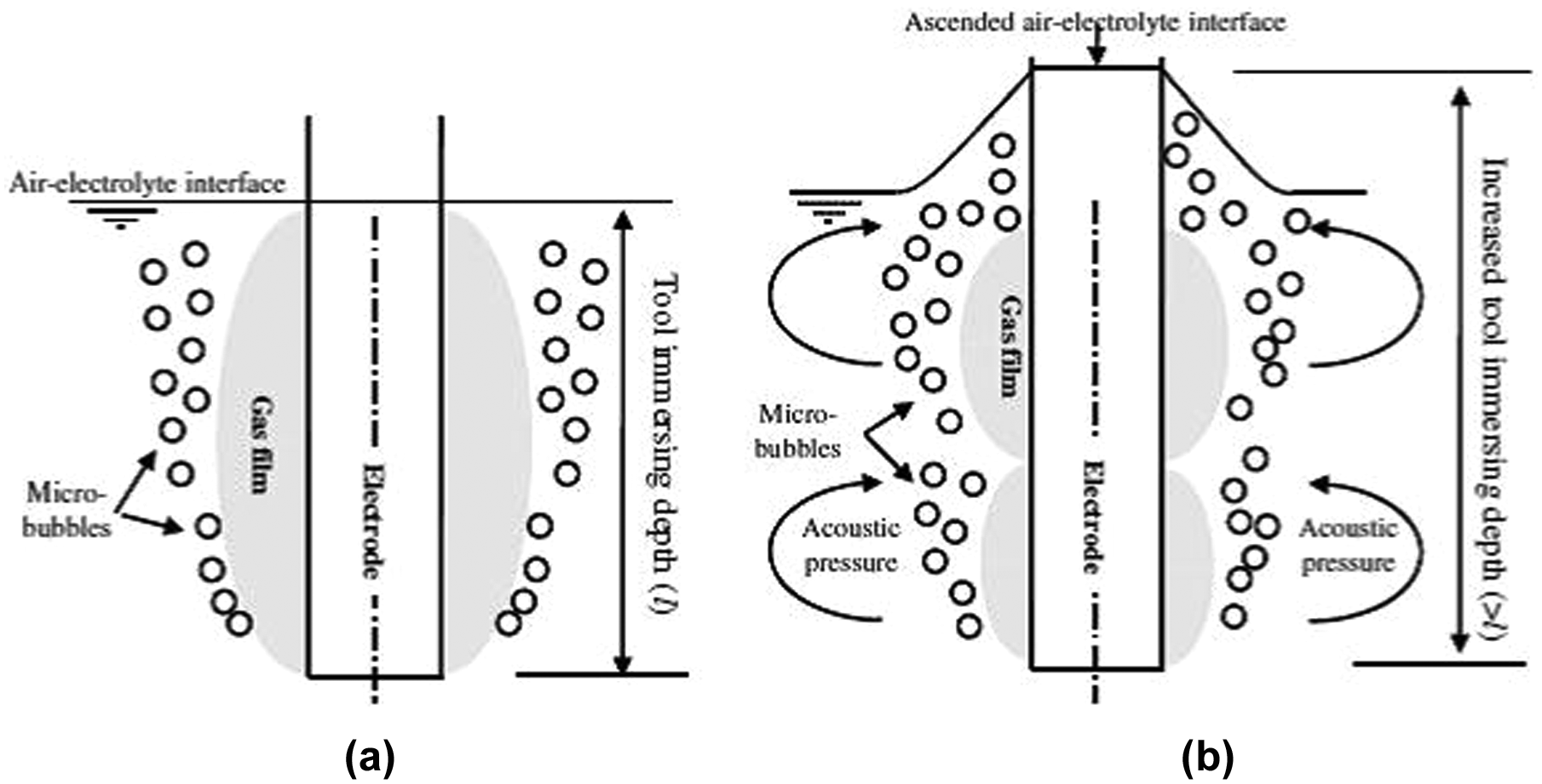
Schematic of shape of gas film geometry (a) without ultrasonic and (b) with ultrasonic vibration of tool (based on Han et al. 15 ).
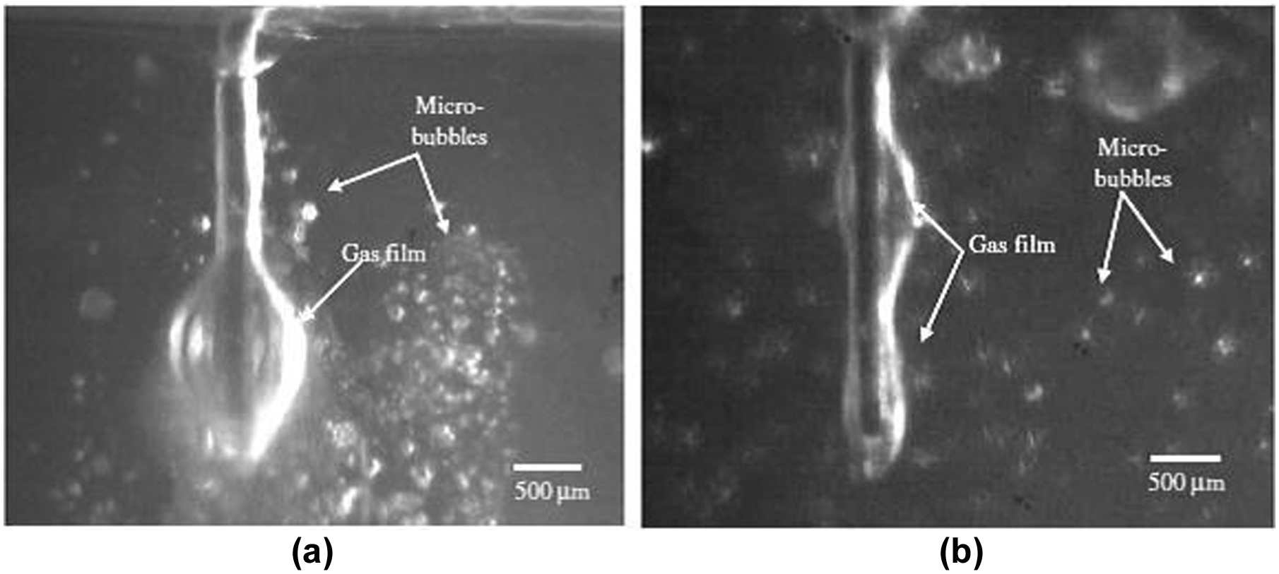
Difference in gas film formation (a) without ultrasonic and (b) with ultrasonic effects (based on Han et al. 15 ).
Tool with side insulation concentrates the spark action at tool tip, which results in minimum stray of electrolysis and reduces the overcut and taper. The intermittent voltage in the form of pulses reduces the thermal damage to workpiece due to cooling action. The impact of side insulation and pulse voltage depicts reduction in overcut and taper. Figure 13 shows improvements in machining depth, reduction in taper and overcut with the use of ultrasonic vibrations of electrolyte.
Shape of machined hole produced with side insulated electrode, 20 wt% NaOH solution, ultrasonic vibrated electrolyte and 35 V DC pulse voltage: (a) tool diameter of 150 µm (b) tool diameter of 200 µm (based on Han et al. 15 ).
Huang et al. 16 investigated that high rotating speed of the tool electrode (cathode) improves the surface quality of walls of micro holes and reduces tool wear when machined an ANSI 304 SS by micro ECDM.
Tool surface roughness–based developments
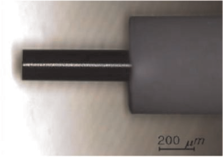
Han et al. 17,18 used a cylindrical tool (brass wire of 50 µm diameter) with microstructures made on the surface of tool as shown in Figure 14 used to machine soda lime glass of 0.4-mm-thick plate. These surface textured tools (Ra = 1.5 µm) enhance the discharge frequency, which results in the improved surface quality of the workpiece as compared to the smooth tool (Ra = 1 µm).
Cutting tool with surface textures (Ra = 1.5 µm) for wire ECDM with a diameter of 50 µm (based on Han et al. 17 ).
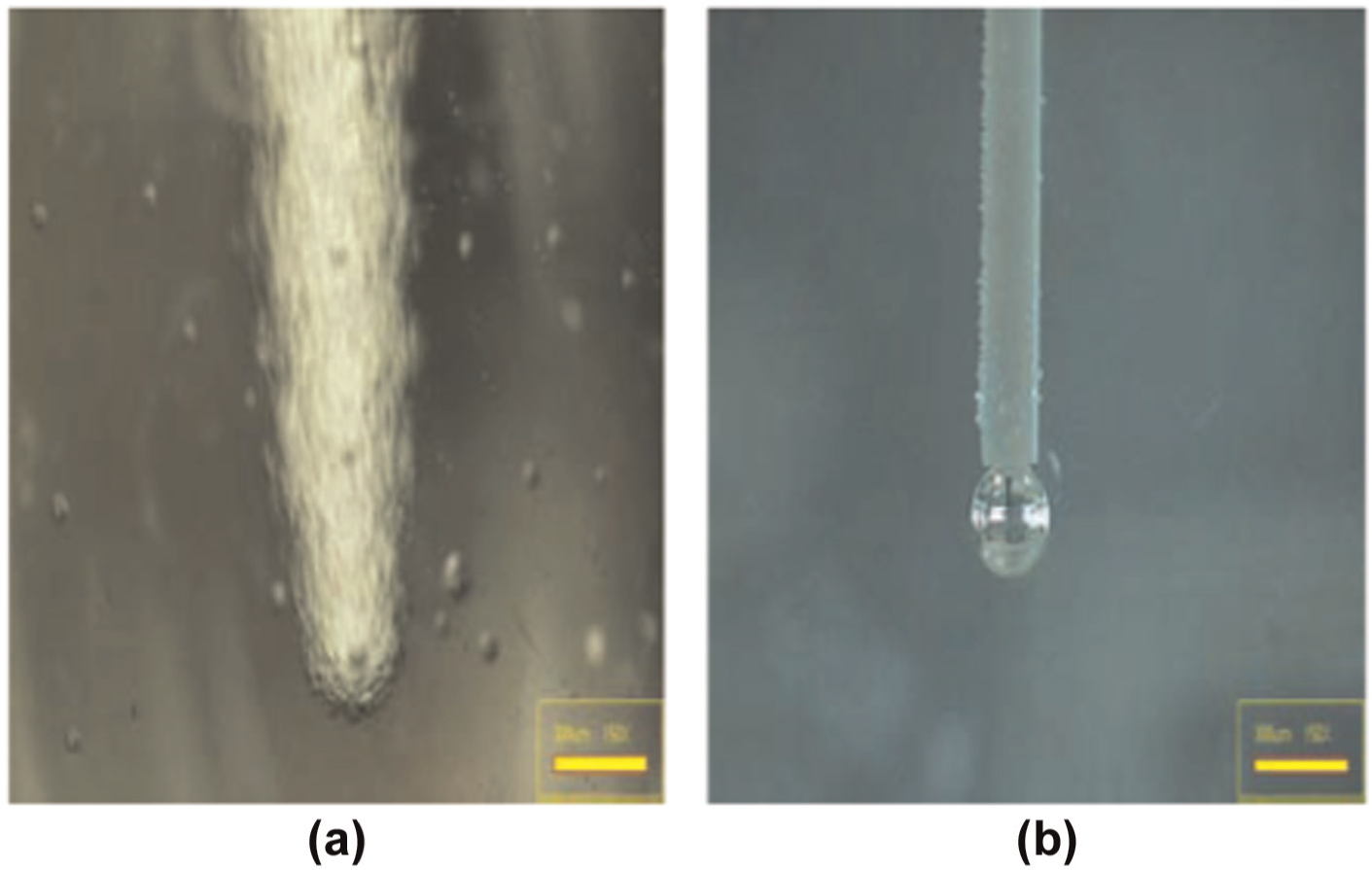
Yang et al. 19 presented in his article the use of three electrodes, that is, stainless steel (SS), tungsten carbide (WC) and tungsten. Surface finish of these tools varies due to physical properties of material in spite of manufactured by the same process (WEDG). Surface roughness affects the wettability of electrolyte, as shown in Figure 15. Poor wettability increases the surface tension of gas bubbles and makes a thicker gas film due to coalescence of more and more bubbles and results in the machining of larger hole diameter. Gas film formation also depends on voltage, which is different for different tool materials. Hence, energy discharge varies with tool material. Tungsten carbide provided the best machining performance in terms of smallest hole diameter achieved and least tool wear as compared to tungsten and stainless steel. Therefore, this makes the WC as the most ideal tool electrode for rapid and precise micro-hole drilling by ECDM.
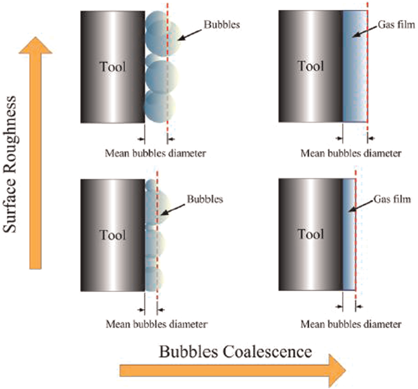
Schematic diagram of bubble coalescence on surface of different roughnesses (based on Yang et al. 19 ).
Chak and Rao 20 experimented drilling of deep hole on Al2O3 using two different configurations of electrodes. A spring fed rotary electrode with diamond abrasive particles embedded on tool improves the cutting ability of the tool due to the presence of abrasive particles and produces an extra electrical discharge as compared to spring fed hollow stationary electrode. Pulsed DC power supply decreases the tendency of cracking and improves material removal at higher supply voltage because of the concentrated release of spark energy and better control of spark stability.
General developments
Jana et al. 21 presented a simplified lumped thermal model for the estimation of tool expansion and tool wear in a gravity feed drilling for few hundred microns in depth. This investigation compared tool wear and thermal expansion for three different tool materials. The materials were stainless steel (SS), steel, and tungsten. Amongst these tool materials tungsten tool had highest tool wear whereas SS tool had almost zero tool wear. Further, SS tool also had highest thermal expansion. Tool length expansion is a function of machining time and pulse off time in pulsed supply. The temperature of the tool is controlled by pulse power supply.
Coteaţa et al. 22 reviewed and experimented on difficult to machine materials by drilling holes less than 1 mm diameter using ECDM. A spring was used under the workpiece to obtain the feed along Z-axis in upward direction. This removed the insulation film on the workpiece including the layer formed at the end of machining. It was revealed that axial tool wear is a function of process parameters such as applied voltage, the capacitance, tool electrode diameter, electrolyte density and depth of machined hole.
Jawalkar et al. 23 presented in his article the fabrication of micro channels on soda lime glass workpiece. Observations show that above 80 V power supply, material removal and tool wear decrease due to dominance of chemical effect of the electrolyte. In the case of higher level of electrolyte concentration, more material is removed and tool wear is increased because of the higher chemical etching effect. Higher feed increases material removal and marginally tool wear because of the fact that it freely escapes the gasses and bubbles, which leads to a stronger and stable gas film and better sparking. His results using the design of experiment (DOE) conclude that MRR and tool wear are maximum affected by applied voltage.
Wei et al. 24 experimentally studied that use of a micro drill increases the machining depth and decreases the radial overcut. Material removal is improved due to generation of chips when gravity feed micro drilling tool is used. Hence, MRR and machining accuracy are improved in micro drilling ECDM.
Cao et al. 25 found that better machining and surface finish are obtained when the tool electrode immersion depth is kept low. It also reduces the required voltage. Pulse voltage increases the surface finish and decreases the hole expansion.
Future scope of work
The present trend of research in ECDM is more emphasized on tool electrode oriented in area of design and configuration of tool. Following are the points, which refer for future scope of work from the literature survey done here, which can carry forward the research in this direction:
Change in tool length can be estimated by measurement of tool wear and thermal expansion during the machining process with respect to time. This will result in increased precision and correction of the measurements of the machined holes.
Tool wear can be considered as a function of process parameters and can be optimized, which are the most influential tool electrode process parameters for the wear.
Wettability of tool electrode can be increased by a suitable manufacturing process or addition of texture. Wet ability influences the rate of bubbles and gas film formation. Such type of surface of the tool affects the machining performance during ECDM.
Different combinations for the tool motion had been presented in various investigations. The process could be based upon the combination of the hybrid of hybrids such as ECDM and ultrasonic machining with an objective of improved surface quality.
A proper shaped cross section of the tool and tool point can be designed for reducing the taper and overcut of hole in ECDM. Therefore, to overcome poor performance of machining and thermal damage of workpiece, a better tool design with optimum process parameters is required.
An orbital motion of the tool for machining process may another alternative to enhance the productivity of ECDM process.
Surrounding of the tool by a magnetic field in ECDM process may result in improvement in surface quality and MRR.
Literature reveals that very rare research work is carried out on ECDM of conductive materials. Therefore, it is recommended that there is ample opportunities exist for electrochemical discharge machining of conductive material as well as semiconductive materials and metal matrix composites (MMCs).
Conclusion
The tool electrode–based process parameters have pronounced effect on ECDM process.
It was observed that tool geometry–based process parameters affect the geometrical accuracy as well as efficiency of the process. The tool geometry refers to suitable design of cross section at the tool point. The improvement in geometrical accuracy is achieved by the use of side insulated tool electrode.
Tool motion during machining may result in better surface quality with enhanced efficiency. This implies that the effect of tool motion needs to be investigated for case to case. The hole geometrical accuracy and increase in depth is achieved with ultrasonic vibration of tool. This effect is pronounced with the use of pulse voltage and side insulation of tool.
Surface roughness of the tool plays a prominent role in ECDM process. Surface roughness–based process parameters affect the process in terms of MRR, tool wear rate and surface integrity of the workpiece. Higher surface roughness of the tool improves the wettability of the tool. Therefore, machining performance can be increased by the optimum surface roughness. Thus, it can be recommended that textured tool can provide better surface finish and machining efficiency.
The general developments in the process include reduction in tool wear, tool expansion and increases in machining depth. This is achieved by suitable modifications in the feed, temperature and electrolyte concentration of the process.
The major capabilities of ECDM are microelectromechanical systems (MEMS) applications such as localized surface modifications, microstructure fabrication, micro-accelerometers, micro-reactors, micro flow sensors and micro-pumps.
Footnotes
Acknowledgements
The corresponding author sincerely acknowledges to Elsevier and IOP for permissions regarding reprint/reuse of figures from publications.
Declaration of conflicting interests
The authors declare that there is no conflict of interest.
Funding
The authors would like to gratefully thank for financial support by Science & Engineering Research Board (SERB), Department of Science & Technology, India (Grant Code SR/S3/MERC/0070/2012).