
Abstract
In the joinery sector, several tons of wood are processed every month. Exploitation costs must be kept low for achieving reasonable margins. Therefore, tool life is an important issue to study, looking for ways of making it longer. There are different types of wood involved in this application, and a value to establish the difficulty of machining one or the other is interesting. For this purpose, the concept of specific cutting force is introduced in this work. In the work presented here, three issues are regarded: (a) three typical woods are characterized by means of the specific cutting force as it is commonly done in the metal industry, (b) coatings are tested for high-speed steel and cemented carbide tools, and (c) tool performance is defined by admissible values of flank wear. The field tests performed showed that the coating of tools could be a good choice for this application.
Introduction
In 1906, F.W. Taylor presented the basis and fundamentals of speed-and-feed-calculating slide rules, still used in machine shops today. Among Taylor’s multiple contributions to the machining science was the basic formula that relates cutting speed with tool life, the tool life being determined by the physical measurement of flank wear. Since then, a lot of contributions lead machining to be considered a mature technology concerning metals and metal alloys. Thus, in the 1940s, machining models based on analytical approaches appeared, 1 starting previously with kinematics of process. 2 The specific cutting force (or energy) was defined as a way to obtain machining forces, and so providing a relative value of the machinability of different alloys. 3 Nowadays, no one could comprehend machining of metal alloys without these approaches. Similar concepts to metal machining were also investigated in the case of wood machining, 4 in which the chip formation process, the three different types of chip of the wood machining, and the specific cutting force were analysed.
Woodworking origins were different to metal machining ones. The current field of composites, both carbon or glass reinforced fibre ones, is a bridge between the traditional gap separating the metal and wood applications, with experts of both field working hard on the trimming, routing, and drilling operations on composite boards.5–7 There are recommendations about how to perform machining tests, as the ASTM D1666-11 8 where the main outcomes from testing are defined (roughness, surface aspects, fibre damages).
Compared to metal alloys used in mechanical engineering, wood is an anisotropic and heterogeneous material. Besides, in wood processing applications, dimensional accuracy is much lower than in metal machining, but many other problems that are not present in the machining of metals may appear. Moreover, cracks may occur in workpiece below the working plane due to different reasons such as fibre orientation, wood knots, or excessive humidity in the workpiece. Generally, these cracks make the piece rejected, especially if the wooden piece is relatively thin. Furthermore, a chip thickness too small or too much moisture can cause the wood tissues to be deformed instead of cut. Coolants are not used in wood cutting due to their effect on wood.
In wood machining, taking into account the usual classical applications, that is, for log or trunk’s peeling, furniture making, sawmills for construction lumber, or joinery applications, there is not a general tradition of considering tool life as the key aspect for cost optimization. The concept of specific force to determine forces and therefore torques and power consumption is not used very often, surely because there are practical difficulties for measuring cutting forces at high cutting speeds and because power consumption is not a sensitive indicator for tool wear. An exception is sawing, where a few works tackled this concept, as is the case of study by Porankiewicz et al., 9 and turning as in the study by Wu et al., 10 in the latter a parabolic increase in tangential cutting force with layer section is stated. Sawing was studied in the literature, 11 applying process knowledge to reduce vibrations and tool wear. Nevertheless, in wood machining, tools are often replaced by immeasurable criteria, such as ‘bad noise’, ‘high vibration’, ‘smoke’, or ‘smell of burnt wood’ or others derived from user’s previous experience. Of course some companies make recording of tool changes and sharpening cycles, especially if very expensive polycrystalline diamond (PCD) tools are used, as it was the case shown in Figure 1 for routing of Formica™ boards. However, this is a big company, not representative of small and medium enterprises, as usually sawmills, furniture makers, or joinery shops are. Other tool makers are introducing technical reports for the adequate use of tools, given values of recommended cutting speeds, 12 ranging from 50 m/s with high-speed steel (HSS) tools to 100 m/s with hard metal (carbide) tools for softwoods, and a 30% lower speed for hardwoods. The use of downmilling (climb milling) and upmilling types of milling is also related with the final finishing of surfaces.
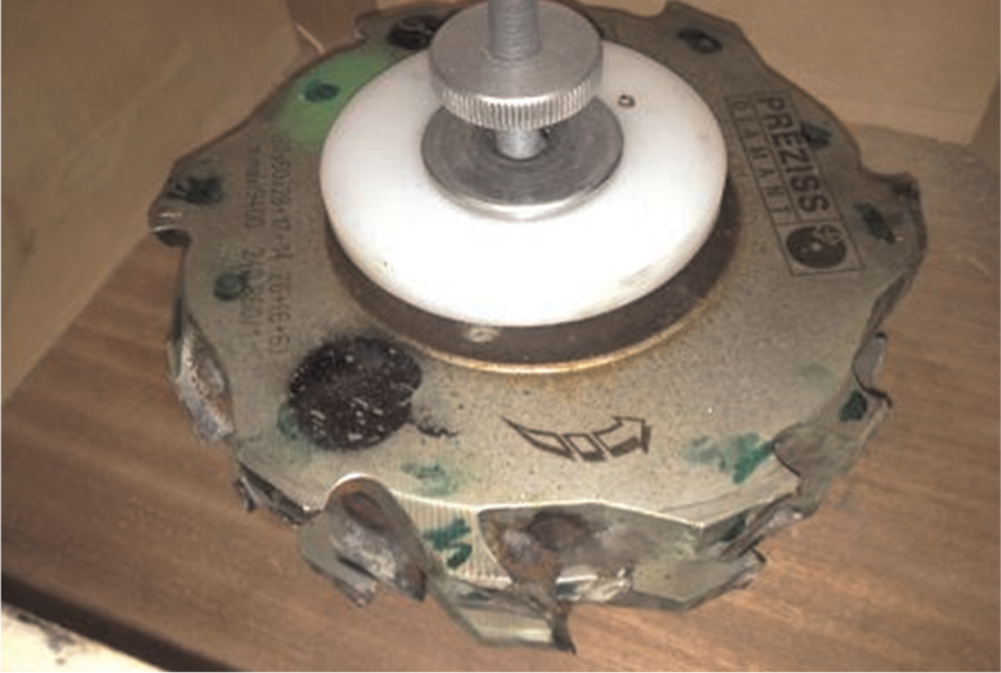
A ∅ 280-mm disc with 18 PCD inserts for routing compacted laminated boards.
Joinery is a part of woodworking that involves joining together pieces of wood to produce more complex items. Some wood joints employ fasteners, bindings, or adhesives, while others use only wood elements. The elements are machined to obtain the joint profiles (for example, male–female shapes), and the required lengths and thicknesses for each beam or pillar. Computer numerical control (CNC) commanded machines are used, in which several milling heads or drilling stations are employed. Usually, the process is fully automatic and with a high production rate. The list of all components and specifications is defined by powerful design software. The flexible CNC machines are used in all timber construction sections from carpentry joining, contract joining, log house construction, prefabricated house construction, and glulam joining to the production of playground equipment. Thanks to the machine handling systems, round logs, log house profiles, T-sections, or multiple layers (stacks) can be fed in. All items are manufactured in the final dimensions and shapes from the computer-aided design (CAD) and the following bill of materials list.
The best cutting performance in wood business is provided by PCD tools. Grades with medium-size grains (bigger than 2 µm) and high cobalt binder content (in excess of 20%) are usual. PCD offers several advantages over cemented carbide, including increased abrasion resistance and longer tool life – typically 100 times or even greater. Some authors studied the causes of premature wear and damage of the PCD cutting edges. Common damage mechanisms are microcracks and chipping due to process vibrations, or originated from a not accurate insert set-up at the tool pre-setting stage.13,14 PCD always suffers from its low toughness, so a correctly balanced tool must be used in order to reduce vibration issues.
On the other hand, cemented carbide inserts are much cheaper, but with a lower performance than PCD tools. However, their superior toughness makes them appropriate when continuous hits on cutting edges must be undergone. This is the case in the joinery application; cutters are used on single-side and double-side edger machines for milling different panel materials and varying layers. Figure 2 shows two carbide inserts of K20 grade, square of 30 mm side, new and worn, after 2 months of work in two shifts per day, 5 days a week. Other forensic analyses are shown in Figure 3 for other similar inserts. It was impossible to obtain more information of the amount of work made by them, for the lack of tool control of the company, in this case a 45-worker joinery workshop.
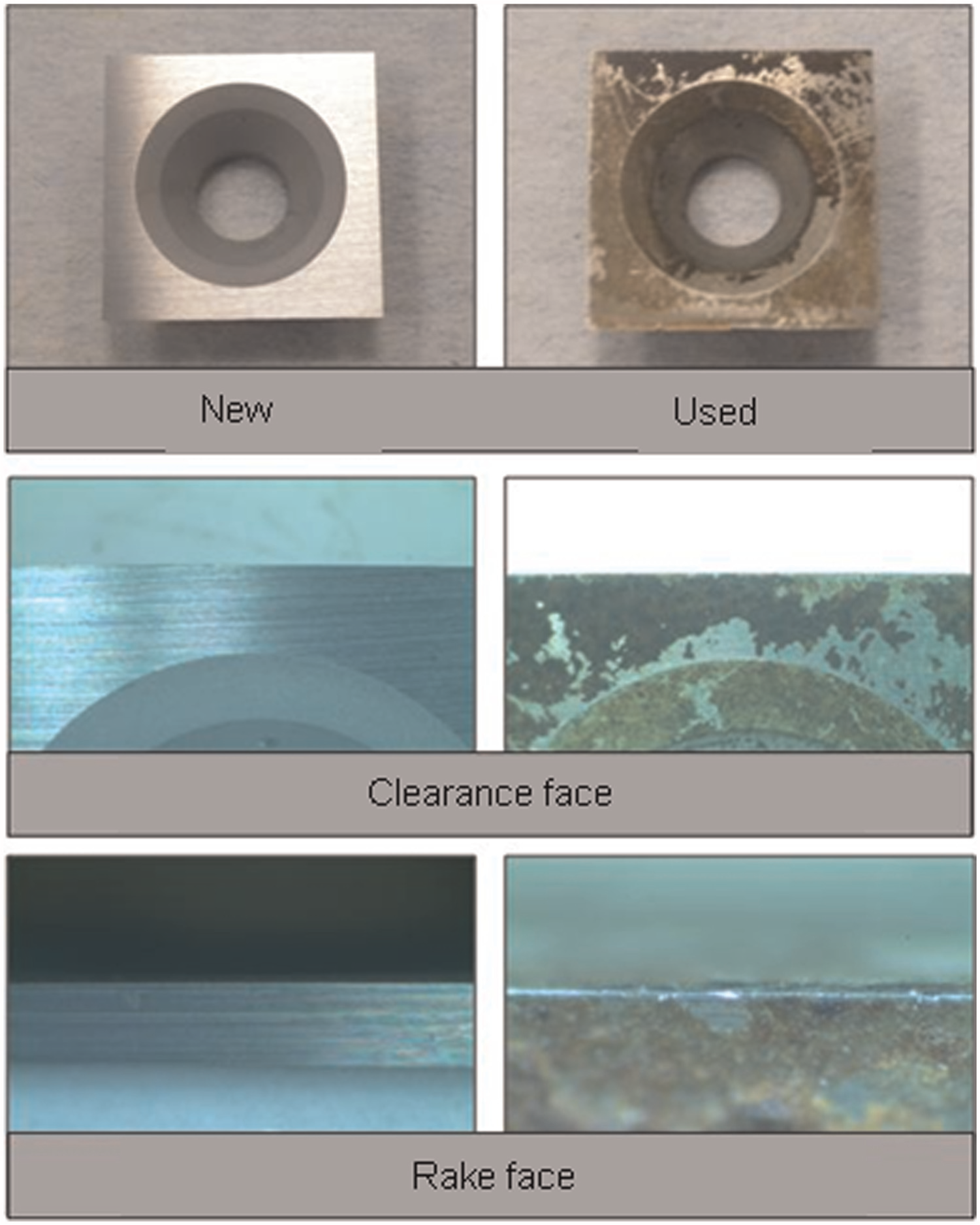
New and worm square carbide inserts after routing 2 months, two shifts per day.
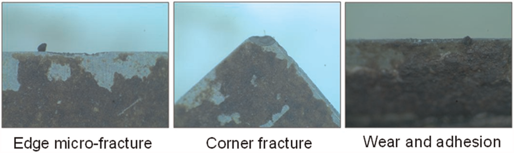
Three typical failures of carbide inserts after 2 months of work.
In joinery, operations are similar to face milling and peripheral milling of metal machining. Therefore, tools require different size and configuration, from large-diameter polygonal discs with inserts located at boundary edges (in the same way shown in Figure 1), up to small-diameter integral tools similar to endmills for slotting and routing operations. In the former, cutting edges are provided by cemented carbide inserts (with several cutting edges per inserts and easily replaceable), whereas in the latter single or two flutes endmill-like tools are manufactured in carbide or HSS. Nowadays, there is a clear tendency to use carbide tools, with works published about the carbide behaviour on wood. 15
Sintered carbide tool is the first choice today when machining metals. Tool performance improves by applying a surface coating, made with chemical vapour deposition (CVD) or physical vapour deposition (PVD) technologies. 16 Carbide is also a prime choice for wood cutting. Sheikh-Ahmad and Bailey 15 concluded that the main wear mechanism for cemented tungsten carbide (WC) tools in machining particle board is the removal of the binder phase by plastic flow and micro-abrasion, which is followed by fragmentation and dislodging of the WC grains.
The positive balance between the coating cost and the increased tool performance lead users to ask for coating application. Thus, in Benlatreche et al., 17 CrAlN was used; nose width (round edge) versus the cutting length after routing was analysed, for medium density fibreboard aimed at furniture production, resulting that a CrAlN film with 5% of Al improves the wear resistance of carbide inserts in the routing of standard and fireproof boards but not in the case of the waterproof one. Similar outcome is referred by Faga and Settineri; 18 here different surface modifications such as nitriding, application of anti-wear DLC and CrN mono and multilayer coatings on HSS18 and alloy steels were analysed, with no clear improvement in tool life. Warcholinski et al., 19 Labidi et al., 20 and Sheikh-Ahmad et al. 21 also presented a better behaviour of tools coated in wood machining. The use of new advanced monolayer, multilayer, or nanostructurated anti-wear coatings22,23 seems also feasible for joinery. In Beer et al., 22 a main conclusion is that after 1600 m of cutting, the tool edge wear of tools covered with CrN was reduced by 50%. Besides PCD and cemented carbides, some testing also was performed with Al2O3 inserts, as shown in Gogolewski et al. 24
Tool degradation is related to abrasive phenomena on one hand and chemical attacks by the wood natural resins on the other. Kusiak et al. 25 studied the influence of CrN coating on the thermal phenomena during wood composite cutting (in this case medium density fibreboard). The heat flux in the knife was used as the thermal indicator of the coating impact. Slight increases in temperature below 50°C were recorded using micro resistor with weak thermal inertia. Even with the usual drift derived from the distance between sensor tip and cutting edge, these increments explain that temperature is not the key factor for tool degradation. HSS and carbides withstand much higher temperatures without damage.
In works oriented to furniture manufacturing, the main outcome considered was the final surface aspect, including roughness. This is the case of the work done by Malkoçoğlu. 26 This study was carried out to determine the properties and surface roughness of naturally grown different woods, such as Oriental beech, Anatolian chestnut, Black alder, Scotch pine, and Oriental spruce, completing a previous contribution. 27 A main conclusion was the relation found between cutting edge geometry and surface quality in planning operations, recommending low rake angles (15°–20°) for hardwood, and a slightly higher rake angle (15°, 20°, and 25°) for softwoods. At the view of these rake angles, it can be said that tools for wood machining are more acute than those for metal cutting in order to avoid wood damage, as it will be shown in Figure 4. Thus, in the metal machining, case values of 20° are only suitable for light alloys machining without thermal treatment. Neutral (0°) or even negative rake angle tools are not unusual for difficult-to-cut alloys. Another key work for understanding surface roughness is that by Sütçü, 28 for edge-glued panels, regarding all relations about input parameters and final roughness. Ra values for walnut and beech (3–4 µm) were found and slightly higher ones for chestnut panels (5 µm approximately). Models for roughness in milling were investigated, 29 but they are difficult to be applied in wood milling.
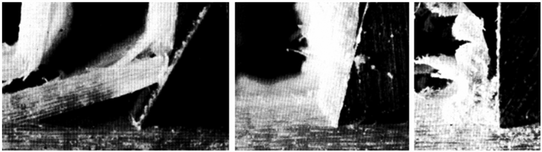
The three types of chips and cracks in wood machining: type I (left), type II (middle), and type III (right). 1 In the cutting perpendicular to fibres, type III is the most usual, but in milling the cutting direction is always changing.
The work presented here is focused on defining three useful aspects to export the ‘way of working’ in the metal machining to the field of joinery applications. Joinery business has increased in size and investments in the last 10 years due to the good adaptability of wooden structures to ecological issues. For instance, in the Basque Country (Spain), it is an increasing activity, where companies are demanding reducing exploitation costs. Other wood sectors are also working on optimization as is the case of the wooden furniture manufacturing industry concerned about how much wood is wasted into the production process and how this is translated in financial issues. 30 The results in this work indicate that during processing, 7% up to 40%–50% of the annual supply of wooden raw material become residues.
In joinery, tools are now being considered a consumable instead of a fixed cost, analytically imputable to removed wood volume. For this very purpose, three aspects are addressed hereinafter:
Determination of an equivalent specific cutting force for three common wood types, namely, old oak (Quercus robur), and dual opposite laminate (DUO) usually made by gluing two Douglas fir timbers and straight Douglas fir. DUO increases the bending strength of wooden beams. The wood main characteristics are gathered in Table 1.
Laboratory testing of a PVD coating, making use of HSS endmills with a high rake angle cutting edge. Tool life is measured, recorded, and plotted to obtain the typical flank wear versus cutting length curves.
Field testing performed in an end user, of tools with several coatings applied on cemented carbide inserts. Along with the above coated HSS tools, the scope of this work thus covers the most common joinery operations.
Three woods for joinery.
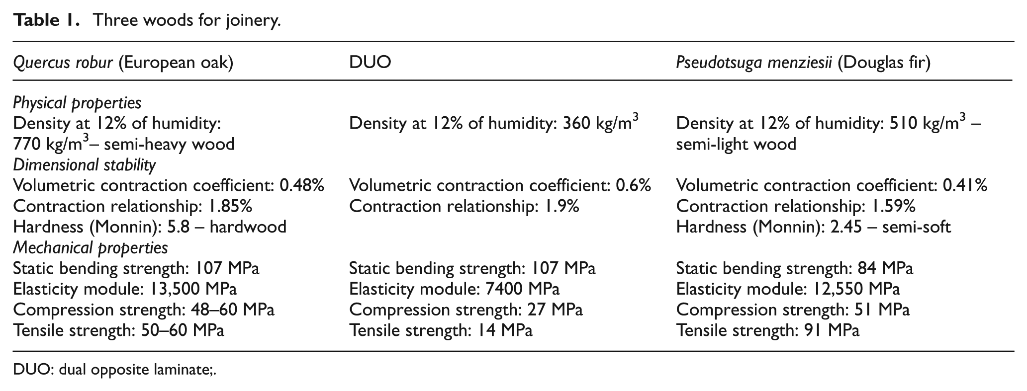
DUO: dual opposite laminate;
Wood machining characterization
The first task of the approach was to apply a concept commonly used in metal machining, specific cutting force – the amount of force measured in Newton to remove a section of 1 mm2– to wood machining. Table 1 shows the basic characteristics of the three different woods used in this article. On one hand, European oak is a leafy tree, typical in construction of houses in central Europe and northern countries, very common in the past centuries for beams and pillars. In renovation of these buildings, civil regulations force to use or even reuse this wood due to its consideration as historical heritage.
On the other hand, DUO is a class C-24 resistance wood, obtained from Douglas fir. These types of wood are classified relating to their structural resistance, in EN 338:2009, Structural timber. Strength Classes. The Douglas fir is another example of a coniferous species used in joinery, usually in a laminated form, or as a part of DUO products. DUO is in the group of glued laminated timber, also called Glulam, a structural timber product comprising a number of layers of dimensioned timber bonded together with durable, moisture-resistant structural adhesives. As shown in Table 1, the compound DUO presents an enhanced tensile strength, meanwhile oak is a classical high-resistance wood as well, and the Douglas represents an intermediate. However, for machining issues, straight Douglas fir and DUO are expected to behave the same because they are the same raw wood.
The set-up for testing and recording of cutting forces when machining the three woods was the following one:
Machine: a three-axis milling centre was used, with a high-speed spindle reaching 24,000 r/min and providing power 24 kW, the latter much higher to that demanded by the wood milling process. Linear feed was able to reach 24 m/min.
Wooden workpieces were rectangular-section prismatic blocks, bolt on a dynamometer plate using ∅ 12-mm screws, inserted in holes previously drilled in the required plate positions (see Figure 5). Wood fibres were perpendicular to toolpaths, for reducing the risk of suffering longitudinal cracks along tool trajectories, as it is shown in Figure 4. Type II shown in this picture is the usual recommended method for wood cutting.
Kistler® dynamometer plate of type 9255B was connected to an amplifier and used for measuring and recording of cutting forces during experiments. Special care was taken about the tooth impact frequency, to avoid resonance with the dynamometer natural frequencies, with values of 2 kHz in X- and Y-axes and 3.3 kHz in Z-axis. These values led to use of rotational speeds below 13,000 r/min, with four-teeth tools.
Tools were four-teeth ones, in HSS, ∅ 20 mm, helix angle 30°, with high positive rake angle of 30°. Tool tip corner was very sharp, radius approximately 0.
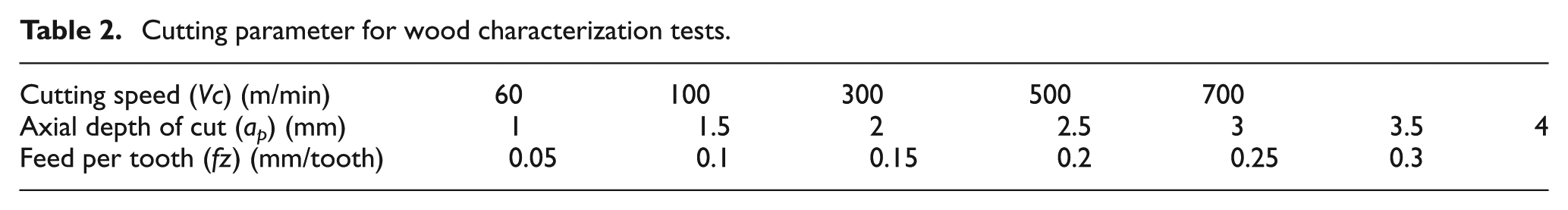
Operation was slotting, as shown in Figure 5, applying the cutting speeds (Vc), feed per tooth (fz), and axial depth of cut (ap) in Table 2.
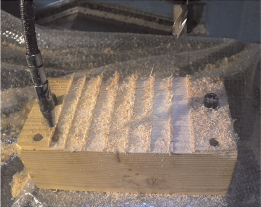
View of the experimental set-up of the slotting test.
Cutting parameter for wood characterization tests.
Cutting force components were recorded in slotting, making it easy to match the maximum value of Fy with the maximum value of tangential force because they both match when values of Fy are maximum. Tangential force can be expressed as
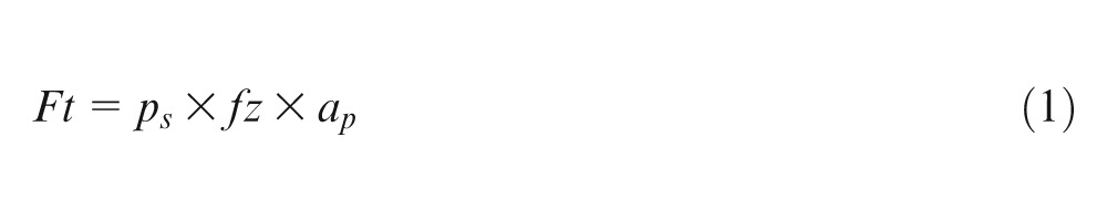
from which the value of ps is directly obtained.
If maximum Ft is obtained, the values of maximum torque T and maximum power consumption are easily calculated as
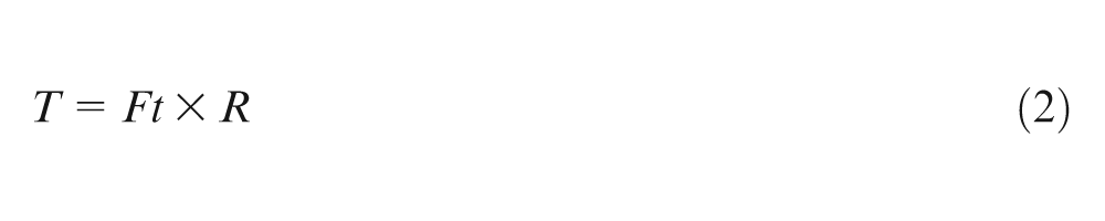
R being the tool radius and ω the spindle rotational speed. These values could be useful to define the machine spindle requirements for industrial applications, but the machine used in this work had torque and power in excess of the calculated values.
Oak wood
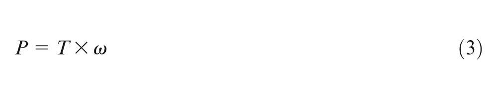
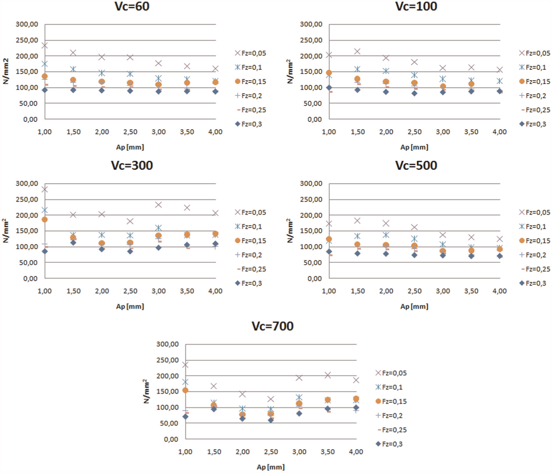
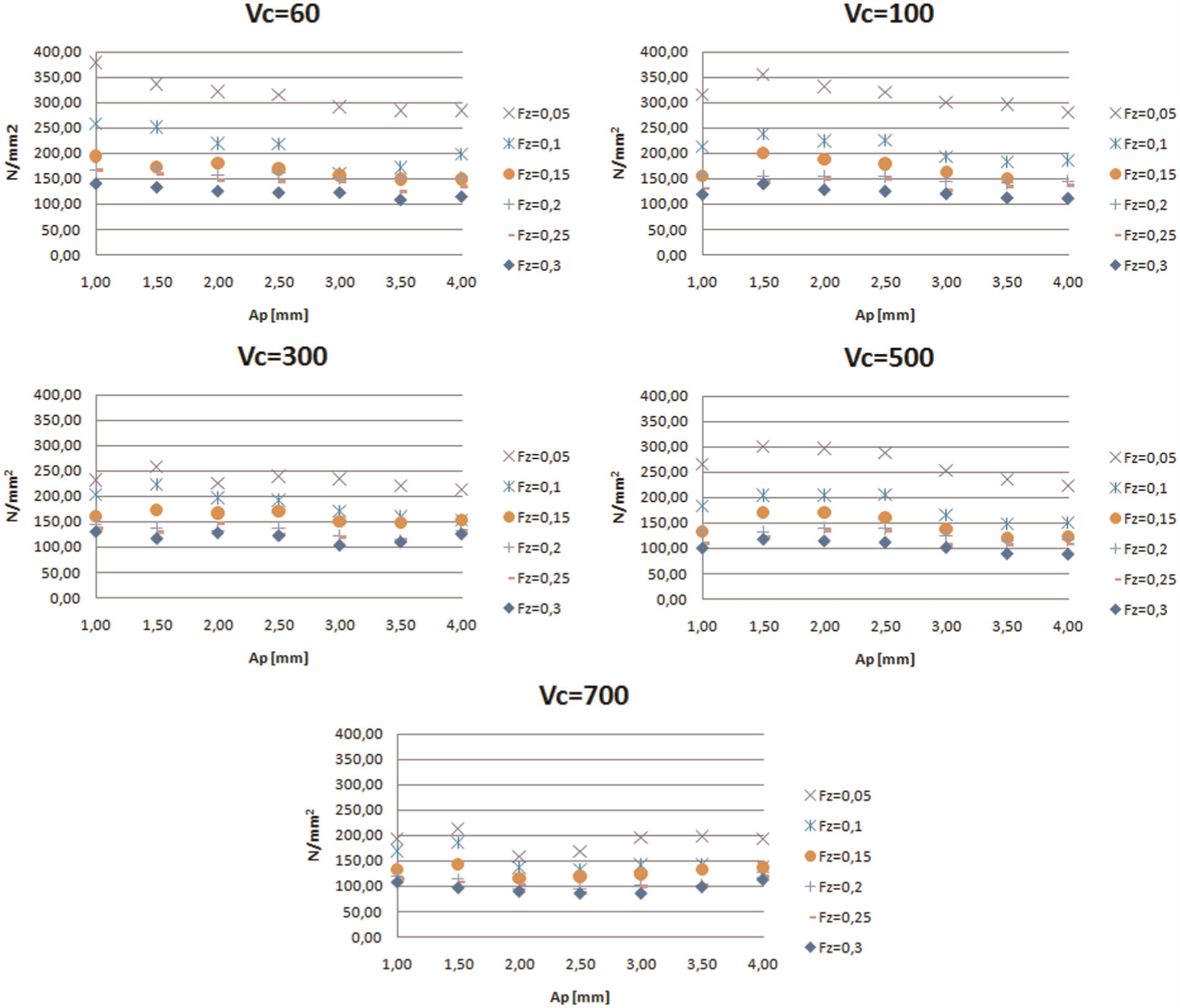
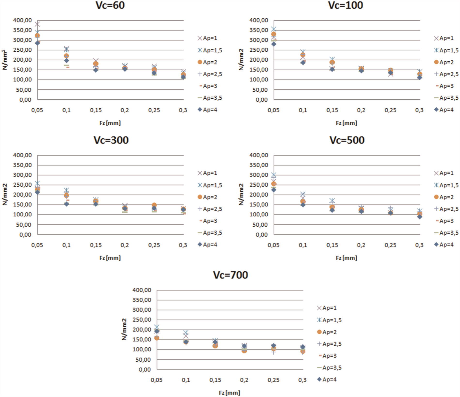
Values of specific cutting force for oak are shown in Figure 6, in this case plotting results for different speeds, and each of them for several values of feed per tooth versus axial depth of cut. In Figure 7, specific cutting force is plotted for several axial depths of cut versus feed per tooth. From Figures 6 and 7, it is conspicuous that there is no constant value for ps, showing a great reliance on fz and a much less one on ap. As in the case of metal cutting, specific cutting force is not affected by axial depth of cut, with the exception if it is of the same magnitude as the tool tip radius. This fact explains the slight increased values when ap is low.
Values of the specific cutting force for several values of axial depth of cut at different feeds per tooth, in the case of oak wood.
Values of the specific cutting force for several values of feed per tooth cut at different axial depths of cut, in the case of oak wood.
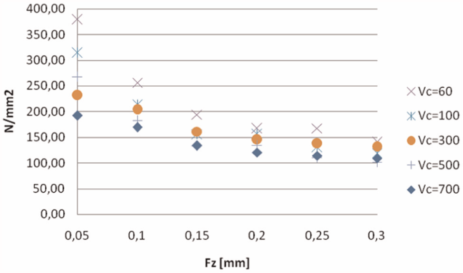
In Figure 8, specific force is plotted versus feed per tooth, for the tested cutting speeds, showing a great reliance on values of feed lower than 0.2 mm. This is also a well-known fact in the case of metal cutting being called ‘size effect’, explained as when the chip section is small; the cutting edge tends to rub instead of to cut. This effect increases forces in the cutting speed direction, as Milton C. Shaw in 1952 defined: ‘It is generally believed this is due to the fact that all metals contain defects (grain boundaries, missing and impurity atoms, etc.), and when the size of the material removed decreases, the probability of encountering a stress-reducing defect decreases’. Wood and especially old oak contain defects, microcracks, and fibres, along with an elastic deformation capacity, all these aspects contributing to this ‘wood size effect’.
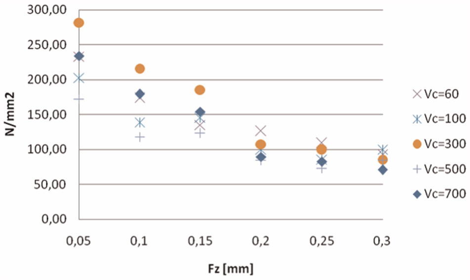
Values for specific cutting force for several values of feed per tooth at different cutting speeds, for an axial depth of cut of 1 mm, in the case of oak wood.
Taking into account the trends shown in the previous figures, two provisional considerations were taken:
Wood machinability should be defined by the value of ps related to a feed per tooth of 0.2 mm or higher and axial depth of cut higher than 3 mm. Using these values, woods can be compared among themselves.
For oak wood, the higher the cutting speed, the lower the forces, as it is also known in the case of metal cutting, in the current technology known as ‘high-speed machining’. In metals, the decrease is explained by the softening effect caused by the generated heat in the shearing zone associated with the chip removal process. This could be a hint for explaining the decrease in forces in wood cutting, but further experimental tests are really needed.
DUO
Just the same graphs were obtained as in the case of oak for the DUO wood: in Figure 9 specific cutting forces versus axial depth of cut, for each tested feed per tooth; in Figure 10ps versus fz for several axial depth of cut values; and finally Figure 11 shows the influence of cutting speed for a fixed value of depth of cut.
Values of the specific cutting force for several values of axial depth of cut at different feeds per tooth, for the DUO wood.
Values of the specific cutting force for several values of feed per tooth at different axial depths of cut, for the DUO wood.
Values for specific cutting force for several values of feed peer tooth at different cutting speeds, for an axial depth of cut of 1 mm, for the DUO wood.
Looking at Figures 9–11, similar conclusions can be made as for the oak case because tendencies were just the same. Some tests carried out on straight fir were in the same order of the magnitude that is absolutely understandable because DUO is made with two fir beams glued together.
Comparing values in Figures 8 and 11, cutting force is 50% higher for DUO than old oak wood at feeds above 0.2 mm, for all the cutting speeds.
Laboratory testing for coating evaluation
After force measurement, a research focused on the increment of tool life using coatings was conducted. In a first stage, the coating used was a PVD of TiCN composition, provided by Metal Estalki®, with a thickness of 1.2 µm. Milling test was made on Douglas fir, the properties of which are gathered in Table 1. Due to the large amount of material needed for wearing the tools, only one coating was able to be tested, and this drawback will require a further research. Tool substrate was HSS, chosen for suffering a higher level of wear and to make evaluation easier (see Figure 12).
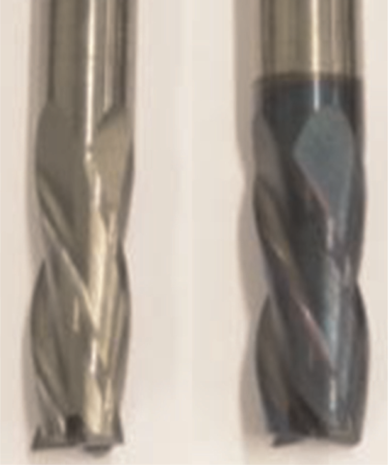
Tools used in the test, without coating (left) and coated with TiCN (right).
The set-up was arranged on the same machine and force measurement plate, for comparing one uncoated tool versus one tool with TiCN coating, as shown in Figure 5. In order to use less wood, tools were modified to leave only a single cutting edge, relieving the other edge using a grinder. Another advantage was that the effect of tool runout was thus avoided. Tests were repeated twice for statistical soundness, thus if the results varied by more than 10% between the two similar tests, a new tool was tested again in the same conditions, rejecting the previous one that was different from the repetitive test.
The operation was face milling, with a Vc of 1508 m/min, which corresponds to 24,000 r/min, with a feed per tooth of 0.3 mm, radial depth of cut of 10 mm, and axial depth of cut of 2 mm.
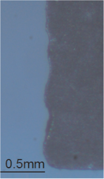
In all the cases, instead of a neat and plane flank wear, the rounding of the cutting edge was the predominant wear. For making a measurement of that rounding, a visual comparison was done using the uncoated tool as a reference. In the test, 30,200 m of Douglas was machined using a TiCN-coated tool, without any signs of extreme damage in the coating film. In Figure 13, for the same machined length, the lower flank wear of the TiCN tool with respect to the uncoated one can be easily noticed. Despite the roundness pattern of wear, the projection under the microscope can be measured as flank wear.
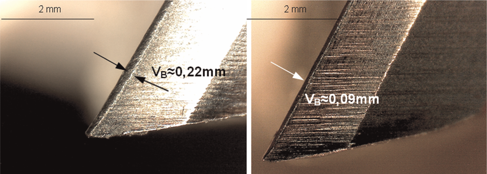
View of the cutting edge for 30,200 m of Douglas fir machined, with tool without coating (left) and with TiCN coating (right).
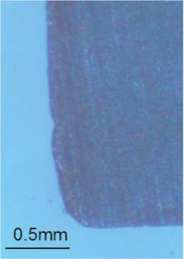
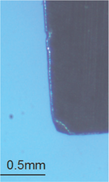
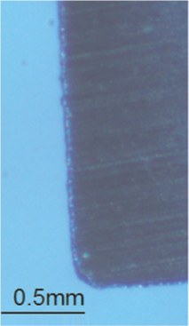
Taking into account tools with the same wear land, as shown in Figures 14 and 15 measured in intermediate states, it gives a ratio of cutting length for TiCN coating/non-coated tools of 2.51 (at 3100 and 7800 m; Figure 12), 2.03 (at 7700 and 15,600 m), 1.97 (at 11,151 and 22,650 m), and 2.23 (at 13,500 and 30,200 m; in Figure 13), respectively, giving an estimate mean ratio of 2.16. That is, a coated tool performs a 2.16 times longer cutting length than an uncoated one for the same cutting edge flank wear, which implies a 116% of improvement.
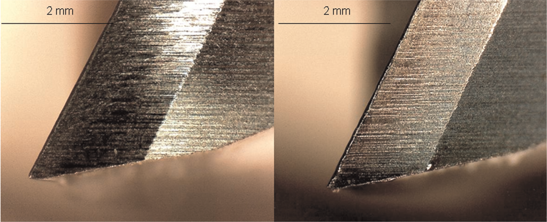
View of the cutting edge after 3100 and 7800 m machining length in Douglas fir, with the tool without coating (left) and the tool with TiCN coating (right), respectively.
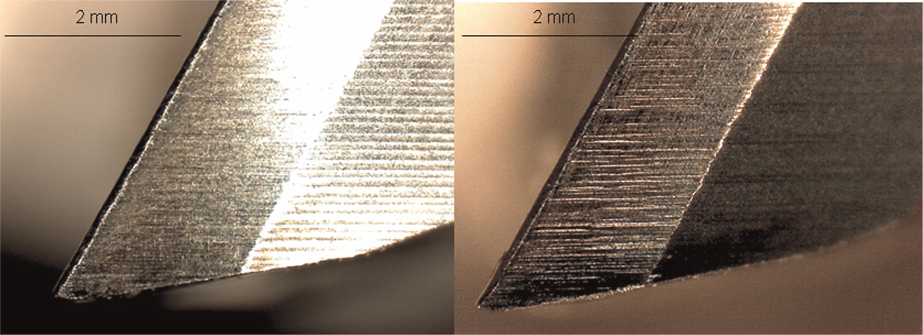
View of the cutting edge for 13,500 and 30,200 m machining length in Douglas fir, with the tool without coating (left) and the tool with TiCN coating (right), respectively.
The good behaviour of coated tools points in the same direction of improvements by Sheikh-Ahmad and Morita, 31 but here the improvement provided by coatings was limited to carbide grades with fine and extra fine grain size and low cobalt content (less than 4%). Coatings applied to grades with higher cobalt content actually resulted in decreasing the wear resistance of the tools, surely due to the difference of hardness between substrate and coating. In this aspect, results with HSS-coated are not in direct agreement with this aspect because HSS is even softer than carbides with 30% cobalt content.
The good behaviour of TiCN coating brought the possibility to propose it and other coatings for real applications, in this case tested in an end-user application, as it is presented in the following section.
Field test for coating performance
A test campaign was performed in real production in a company that used straight carbide inserts without coating. Several cemented carbide inserts for the Hunddeger® CNC machine were coated with the same TiCN as in the previous laboratory test, and two other coatings provided again by Metal Estalki, in this case AlCrSiN coating with a thickness of 1.7 µm and AlTiN coating with a thickness of 1.3 µm. Non-coated inserts were also clamped in the disc-type tool along with coated ones for making comparison easier. Hence, four non-coated inserts and two inserts of each coating were mounted in the same milling plate and put to work in a heavy-duty condition for 1 week.
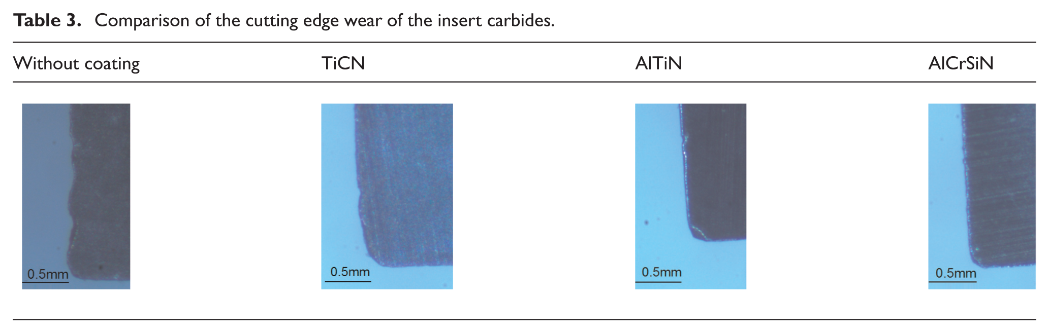
Several factors seemed to affect the condition of the inserts during machining, being disproportionately worn in some of the inserts, probably because a misalignment made in the set-up, so some of the inserts were disregarded. In Table 3, the carbide inserts’ performance can be seen; the lowest wear was in the AlCrSiN-coated insert, followed by the TiCN-coated insert and the AlTiN-coated insert, and finally the non-coated insert. Tool wear was 35% lower in the former case, measuring flank wear directly on the clearance insert face. This fact probably implies an increase in tool life of 40% because the criterion for tool replacement was only defined by this end user as ‘when noise is not good enough’.
Comparison of the cutting edge wear of the insert carbides.
Regarding economic issues, coating could be valued as a 5%–8% of increase in cost with respect to the usual price of carbide inserts, taking into account the commercial price of inserts and the costs provided by the coater provider involved in the project. Therefore, economic performance of this coating was demonstrated and this is a solution worth considering to be used.
Conclusion
A general conclusion is that wood machinability should be defined by the value of ps related to a feed per tooth of 0.2 mm or higher and axial depth of cut higher that 3 mm. Cutting force is 50% higher for DUO than oak wood at feeds above 0.2 mm, for all cutting speeds. On the other hand, for the two woods tested in this work, oak and Douglas fir (in straight and DUO forms); the higher the cutting speed, the lower the forces, as it also occurs in metal cutting. In the metal case, the force decrease is explained by the softening effect caused by generated heat in the shearing phenomenon associated with chip removal. This could be a hint for explaining the decrease in forces in wood cutting, but further experimental tests are needed. However, not only force but other degradation phenomena are involved in tool life.
Thus, TiCN coating improved tool life of the HSS tools in 116%, reaching more than 30 km of cutting length. The results using carbide inserts in a direct final application were not as good as in the laboratory test, but tool life improvement was a real result of the experiment. AlCrSiN coating represents a choice for achieving a tool life improvement, with an expected better performance than the TiCN coating for the carbide insert case.
Wood machining is going to increase in volume in the non-distant future due to the good ecological balance of wood structures. Here, joinery is a key operation and machining an operation to be optimized.
Footnotes
Acknowledgements
We are grateful to Zurtek for allowing to perform final tests in its factory.
Declaration of conflicting interests
The authors declare that there is no conflict of interest.
Funding
The authors are thankful to funding from Basque Government, in the project Manunet WOODCUT. UFI of University of the Basque Country funded this project as well.