
Abstract
Laser irradiation de-coating is a promising new approach for effective coating removal of cutting tools. While this method has demonstrated feasibility for conventional coatings, its use and efficacy on lubricant coating is however yet to be ascertained. This paper reports on the results of excimer laser de-coating of hard DLC from DLC-coated tungsten carbide (WC) substrates. A range of fluence and pulse was studied to evaluate the effectiveness of the de-coating process. Result shows that laser parameters of 7 J/cm2 fluence, 400 pulse and 25 Hz frequency were found to yield optimum results in removing hard DLC coating of 3.2 μm thickness from WC substrates. The experimental work indicated successful laser de-coating of hard DLC coating without noticeable damage to the WC substrate. The capability of this new de-coating process is significant in the aerospace industry as it could facilitate re-grinding and recoating of drills thereby improving economics of manufacturing. The process windows could also be applied in the removal of DLC from other cutting tools and applications.
Introduction
Diamond-like carbon (DLC) coatings are utilised in various applications in the manufacturing industry. In cutting tools, DLC coating is integrated into the design structure specifically to reduce cutting force and tool wear, and prolong tool life. The carbon-based coating offers high wear resistance as well as high hardness with low friction.1–4 However, after extensive use in machining with high cutting speed, the cutting tool will experience significant wear 5 which subsequently leads to non-uniformed delamination of coating. A recent study by Pervaiz et al. 6 has reported that metal cutting also contributes to environmental effect where it generates waste stream outputs in the form of worn cutting tool. Therefore, it seems that the processes of de-coating, re-grinding and re-coating cutting tools for re-use remain more viable economic or cost-saving options for manufacturers. Aside from the economic and tool wear factor, in certain circumstances at industry level, de-coating might also be necessary due to poor initial coating quality or some characteristics of the coating layer being different from the required properties.
A de-coating process is deemed efficient and superior when it is able to remove the coating without inflicting damage to the substrate.7,8 De-coating is usually carried out by means of a wet chemical process, an oftentimes challenging procedure due to (1) the stringent control necessary to regulate reactions between chemical solutions, and ensure no excessive corrosion occurs to substrates and no hazard is posed to operators, and (2) proper disposal procedures necessary in disposing the waste or residue after the de-coating process is completed.
Drawbacks related to chemical de-coating have been reported in several researches. Conde et al. 9 for instance noted that electrochemical de-coating of multi-layered Cr–N based coatings could induce corrosive attack on the substrate. Ardila et al. 10 pointed to the critical need for timing control as current increase for electrolytes in chemical solutions would lead to substrate corrosion while de-coating AlCrSiN from WC-Co substrates. Toboła et al. 8 reported that subsequent coatings deposited on PVD de-coated inserts after chemical coating removal in baths which contain hydrogen peroxide had a marginally lower rate of adhesion. The use of the wet chemical technique could sometimes cause bad contamination to substrate surface due to the cleaning medium. For instance, in cleaning optical elements using chemical cleaning methods, re-deposition of impurities from the chemical solution could re-contaminate the cleaned surface and change the surface topography of the element itself. 11 These factors create an urgent necessity to develop more compatible methods for the cleaning and de-coating processes. In manufacturing industry, the capability of this new de-coating process is significant as it could facilitate re-grinding and recoating of drills thereby improving economic aspects. This chapter thus proposes laser ablation as a viable solution to overcome the shortcomings encountered in chemical de-coating processes.
Literature reviews for laser de-coating
In the early 1990s, lasers were used for removal nano to submicron contaminated layers of semiconductors, electronics and data storage devices. Studies by Tam et al. 12 and Zapka et al. 13 were among the earliest works in the use of lasers in removing nano level contaminate particles from micro semiconductor electronic devices. Both studies reported that particles such as alumina or gold, both about 0.1 to 0.3 μm in size, could be successfully removed from silicon wafer substrates with various types of laser such as Excimer, Er:YAG and KRF laser. In another study, 11 demonstrated that 0.02 μm thick carbon layer could be completely removed from gold film using Nd:YAG laser at 0.1 J pulse energy.
Seo et al. 14 compared the efficiency of three types of laser with different wavelengths in removing 1 μm Cu oxide from copper semiconductor substrates and found Ti:Sapphire femtosecond laser offered better performance in the removal of oxide layers compared to Nd:YAG nanosecond laser and KrF excimer nanosecond laser. Besides cleaning purposes, laser ablation also induces microstructures that could lead to notable improvements in tribological aspects. Detailed examination of crater depth and morphology of irradiated surfaces by Kononenko et al. 15 and Dumitru et al. 16 highlighted the relevance of laser irradiation for microstructuring on either coating or substrate material to improve friction and wear behaviour at reduced lubrication level.
Zhou et al. 17 in their attempt to clean an area of radioactively polluted facilities at a nuclear electrical power industry evaluated a range of fluence to determine the most optimal ablation rate for removing 13 μm-thick Zn coating from carbon steel substrates. The researchers found the coating adequately removed when Nd:YAG laser at wavelength 1064 nm and 470 J/cm2 laser fluence was administered. Ragusich et al. 18 reported on their attempt to remove 20 μm thick TiAlN coatings with Ti:Sapphire femtosecond laser and KrF excimer laser (GSI Lumonics) from titanium aerospace parts. The authors found the ablation rate dependent on laser wavelength, frequency and pulse range. Comparing between two lasers, Ragusich et al. 18 concluded that the excimer laser was more superior and adapting better to the de-coating process of selected coatings.
Using an excimer laser, Sundar et al.19,20 reported that 3 μm thick TiN and 2 μm thick CrTiAlN coatings were successfully removed from WC and HSS flat substrates, respectively. In a subsequent study, the authors evaluated laser de-coating processes on micro milling cutter tools. By optimising the number of pulses, scan speed and beam overlap percentage, they demonstrated that 2 μm TiN and TiAlN were completely ablated from 0.5 mm diameter WC flat end mills. Evaluation of surface roughness (Ra) after the de-coating process showed the value of the de-coated tool well within the permissible range reported for high-speed machining.
In view of all that have been presented so far, the assumption here would then be that laser ablation provides an established method for the removal of layers or coatings from substrates. Depending on the particles or coating to be removed, the mechanism of the de-coating process is varied. Tam et al. 12 and Zapka et al. 13 used steam laser cleaning in the removal of particulates from silicon wafers. Under this method, a thin or liquid film is deposited over the contaminated surface during laser irradiation after which pulsed laser heating of the surface is then applied. This would cause superheating and explosive evaporation of the thin film; the subsequent rapid ablation would lead to the production of large transient forces that overcome the particle-substrate adhesions thereby causing particle ejection.
Literature review on dry laser cutting in many studies pointed to the high propensity of laser wavelengths to be absorbed by coatings or substrates. In this technique, a laser beam is focused on a workpiece material which results in sudden expansion of the surface. Due to the thermal coefficient mismatch between the coating and substrate, cracking on the surface of the material would occur. Explosive removal of coating followed by evaporation is evident by the absence of material re-deposition once the process is completed.11,16–20
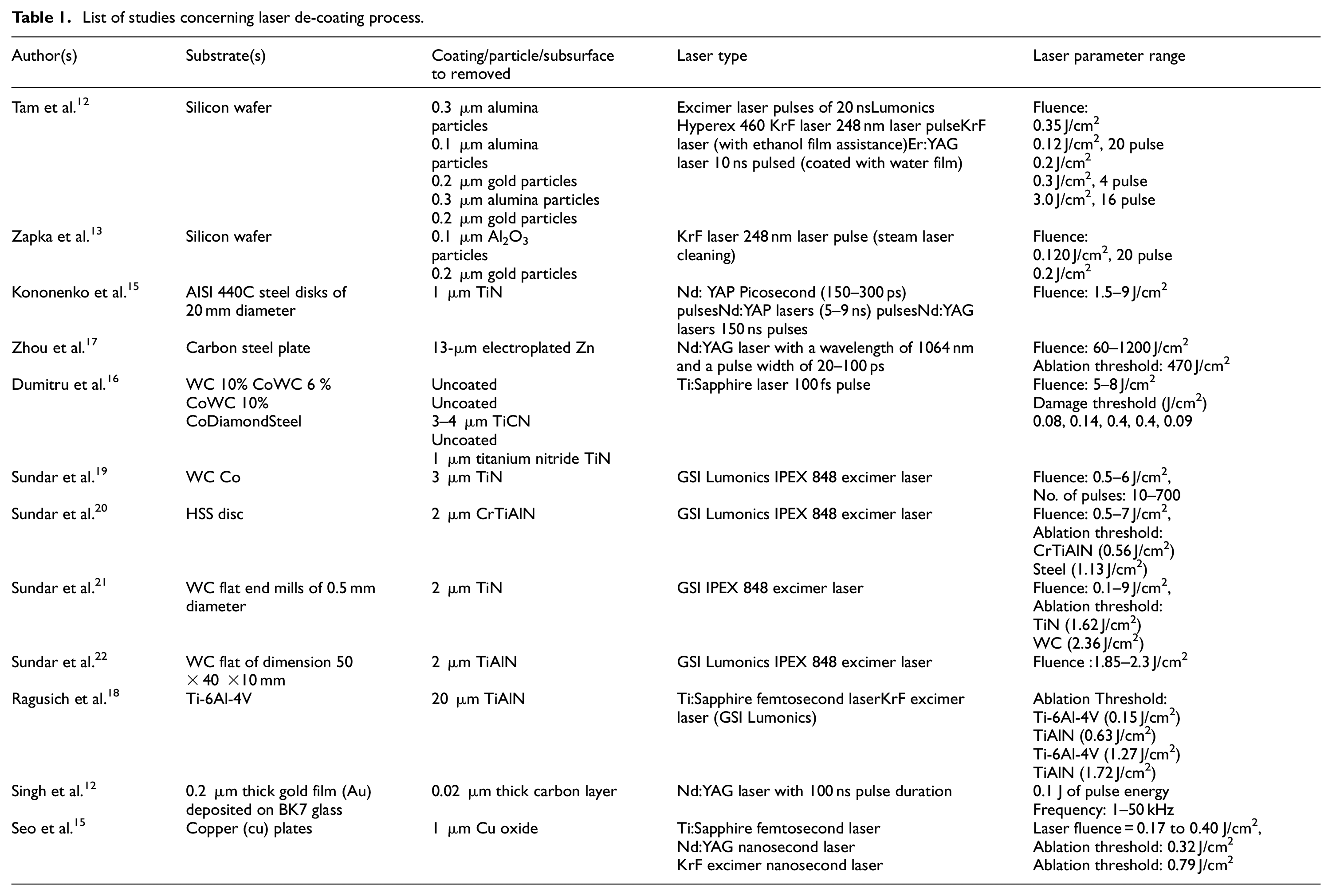
Latest developments in cutting tool de-coating have led to a renewed interest in de-coating studies. Table 1 presents a summary of the studies that investigated the use of lasers for de-coating various substrate types. However, compared to this body of studies on tool de-coating processes which utilised titanium-based coatings in their tests, this current work examined the removal of 3.2 μm thick hard DLC coating from WC substrates using an excimer laser. The effects of various laser fluence and pulse required to strip hard DLC coatings were studied from which the optimum laser parameter required for de-coating could then be established.
List of studies concerning laser de-coating process.
Experimental details
A tungsten carbide (WC) insert coded as TCMT3(2.5)1-MP4 WPP20S – 60° Triangle/Indexable Carbide Turning Insert by WALTER which was previously coated with TiCN+Al203 was used as a sample in the experiment. The thickness of the original coating was 4 μm. DLC coating consisting of hard DLC, CrN and adhesive layers with a total thickness of 3.2 μm and hardness of 2288HV was deposited on the uppermost layer to create a multilayer coating. Coating deposition was performed using a closed field unbalances magnetron sputter ion plating system UDP 850/6 with carbon targets and chromium targets. A chromium interlayer was deposited first followed by a hard underlayers including carbides and nitrides of graded composition to achieve excellent adhesion. Finally, the main carbon layer was deposited from hydrocarbon gas. Electromagnetic coils were used to control ion current density at the substrate during deposition. The accumulated coating thickness for the insert therefore was 7.2 μm. Figure 1 shows the insert substrates after laser irradiation and the thickness layer of each individual coating.
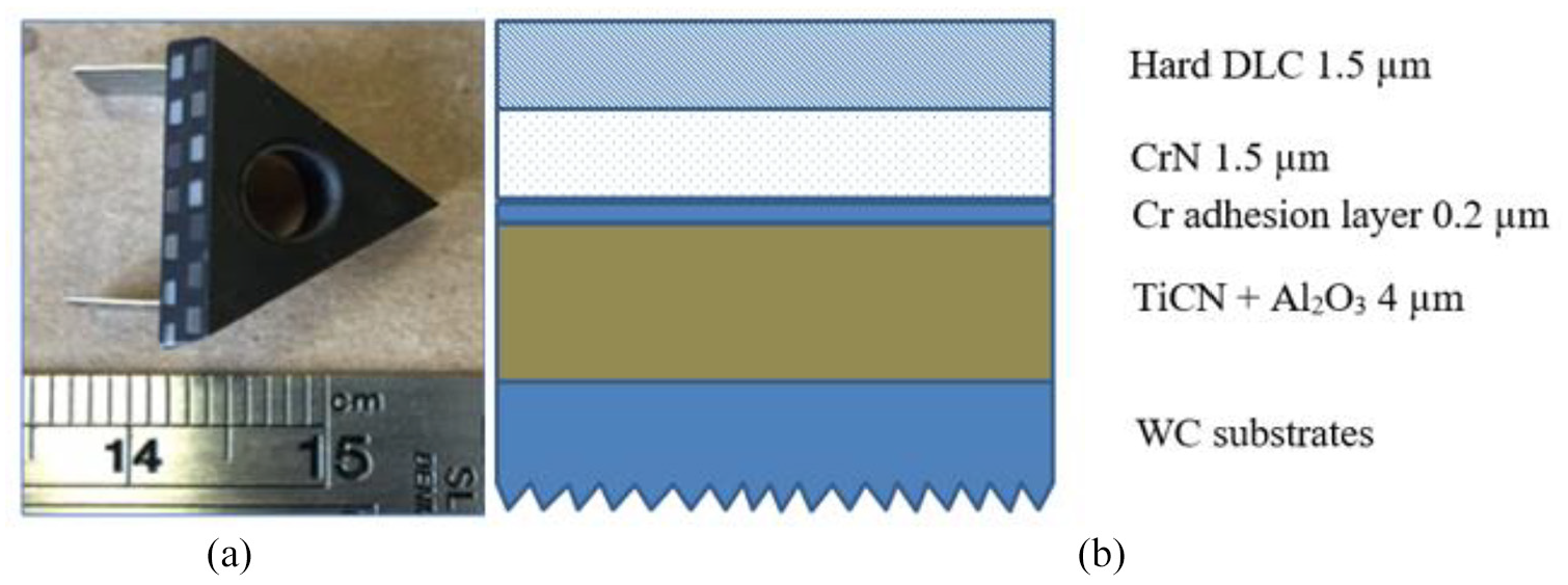
WC insert substrate (a) after irradiated with laser on the side and (b) thickness layer for each coating on the substrates (image not to scale).
GSI Lumonics PM-840 KrF excimer laser emitting output wavelength of 248 nm and 560 mJ maximum power was used as an energy source for the de-coating process. The range of fluence used to irradiate the surface varied from 2 to 9 J/cm2 while the number of pulse ranged from 50 to 400 with the frequency constant at 25 Hz. The selection of fluence parameters was derived from previous studies that performed de-coating from cutting tools. Due to the higher thickness of coating used in this study, a relatively higher fluence was tested. Information given in Table 1 indicates the laser fluence range used in previous studies that served as the benchmark for the current research.
The stationary laser beam de-coating process was performed at room temperature and atmospheric pressure. Figure 2 shows a schematic diagram and the experimental set-up. A laser light was emitted from the main source, directly incident on an objective mask of 1 × 1 cm, which passed through focusing lens (focal length of 100 mm) before hitting the target surface. The distance between the focusing lens to target (u) and objective mask to lens (v) was based on the ratio of 1:10 therefore producing a laser spot of 1 × 1 mm spot size on the target surface. The workpiece was held on a CNC stage which consisted of X and Y axis. The X-axis would move the insert left and right while Y-axis allowed for upward and downward movements. The insert was mounted in a vertical position, allowing laser irradiation on the flank face in perpendicular beam incidence.
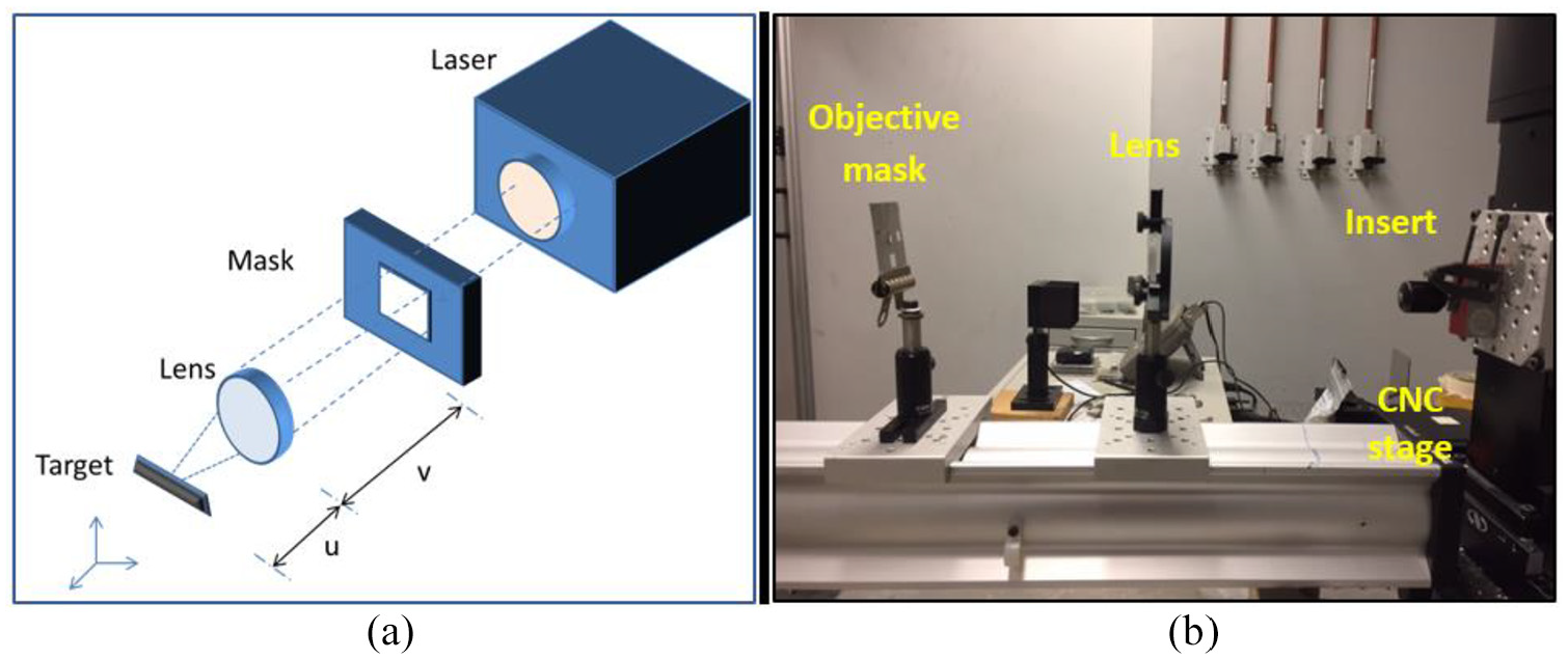
(a) Schematic illustration and (b) experimental set-up of the excimer laser de-coating system.
After the trials were completed, the ablation depth for all irradiated surfaces was examined using a white light optical profiler (Wyko NT1100). This was then followed by a validation of the remaining element composition on the ablated area by elemental energy dispersive spectroscopy (EDX) analysis performed on XL 30 scanning electron microscope. Assessment on surface roughness (Ra) was conducted using a VK-X100K/X200K 3D Keyence laser scanning microscope.
Results and discussion
Ablation depth
Figure 3 compares the variation of ablation depth with fluence and number of pulse for hard DLC de-coating on TiCN+Al203-coated WC insert at a constant frequency of 25 Hz. From the graph it is evident that the ablation depth increased rapidly above 7 J/cm2 as function of number of pulse. This increase in ablation depth could be attributed to the increase of laser absorptivity as the energy became greater. At number of pulses 50, regardless of laser fluence value, the ablation depth was at such a minimal level that its effect on coating irradiation was negligible. An increase of pulse number produced a significant increase in ablation depth.
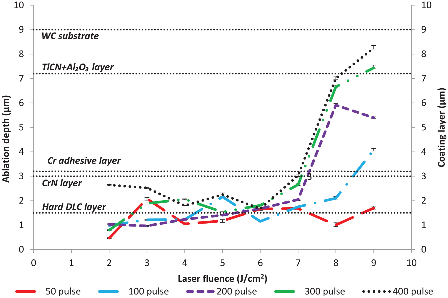
Variation of ablation depth with fluence (Frequency = 25 Hz).
Figure 4(a) to (h) presents the selective optical microscopic images of stationary laser beam de-coated samples using a fluence of 7, 8 and 9 J/cm2. To understand better the excimer laser ablation phase, damages induced on samples with increased pulse energies are depicted. Since material removal rate is very low at fluence of less than 6 J/cm2, the suggested optimal level for removing a selective spot is at 7 J/cm2 upwards. Detrimental effects on the surface were indicated when the sample was irradiated at number of pulses 50. As the number of pulses increased to 100, some parts of the surface demonstrated changes in colour appearance. At number of pulses 200, the entire laser-spot appeared slightly dark (see Figure 4(c)). A noticeable colour contrast in the images was observed as the number of pulse further increased to 300; this suggested that the penetration of laser energy had increased and reached deeper coating layers. When the pulse number reached 400, the incident energy distribution became dominant in the ablation effect as depicted in Figure 4(e). At the same time the carbon film had disappeared entirely from the ablated sample. No significant change in terms of colour contrast was observed when fluence was further increased to 8 and 9 J/cm2.
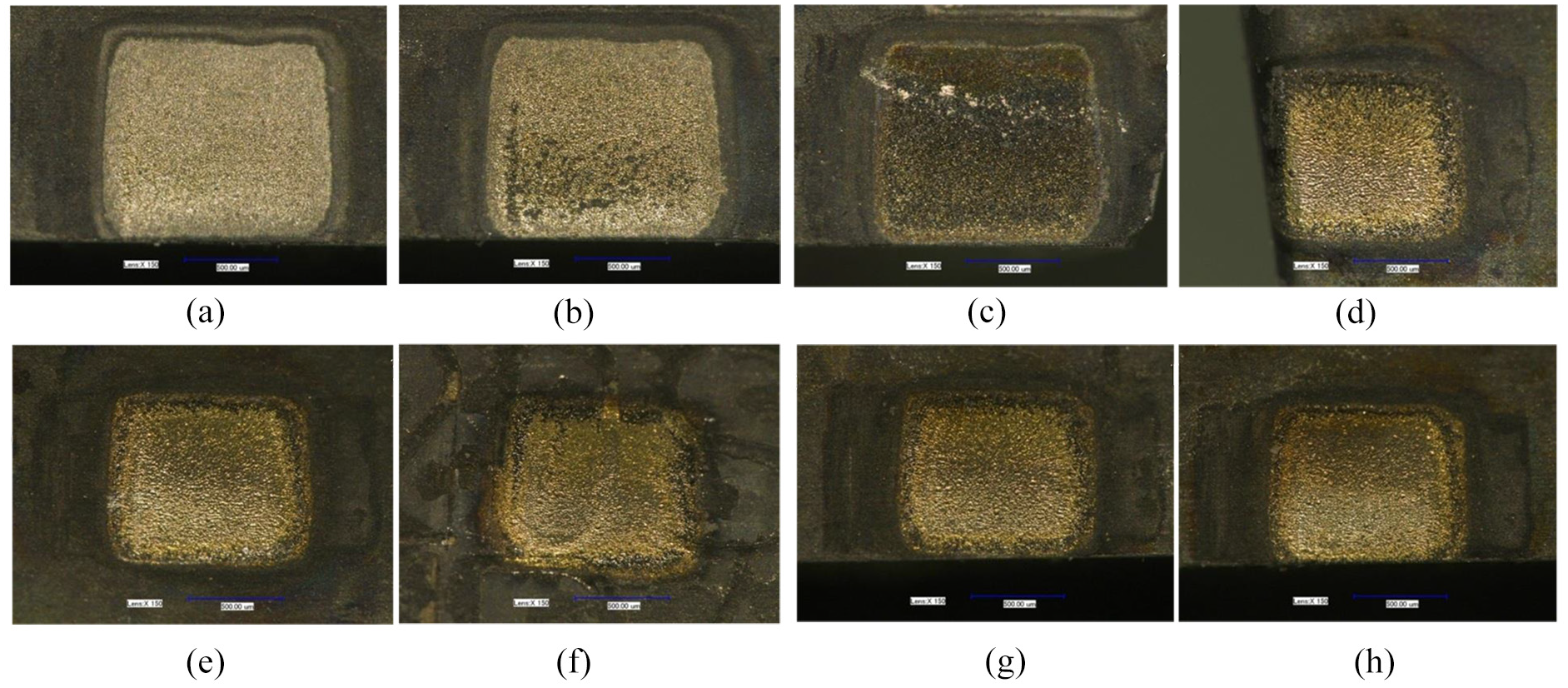
Optical images of laser irradiated area at laser parameter (a) 7 J/cm2, no of pulse = 50, (b) Fluence = 7 J/cm2, no of pulse = 100, (c) Fluence = 7 J/cm2, no of pulse = 200, (d) Fluence = 7 J/cm2, no of pulse = 300, (e) Fluence = 7 J/cm2, no of pulse = 400,(f) Fluence = 8 J/cm2, no of pulse = 200, (g) Fluence = 9 J/cm2, no of pulse = 300, and (h) Fluence = 9 J/cm2, no of pulse = 400.
Using SEM investigation, it was possible to accurately observe the sub-surface modifications and the resultant data used for the determination of the ablation threshold. Initial cracks in the top layer of hard DLC were shown at fluence 7 J/cm2 and number of pulses 50 to 100 (see Figure 5(a) and (b)). The surface crack formation in the coating was due to the thermal stress gradient between carbon and chromium brought about by thermal expansion. The cracks became more pronounced when the number of pulses were increased to 200 as shown in Figure 5(c). It could be seen from the optical images that the increase of fluence affected coating ablation. The cracked film completely disappeared as pulses number were increased to 300 and 400 suggesting that particular layer coatings had been fully penetrated and removed (see Figure 5(d) and (e)). The appearance of pores on the samples at much higher fluence confirmed that the substrate had been exposed (see Figure 5(g) and (h)).
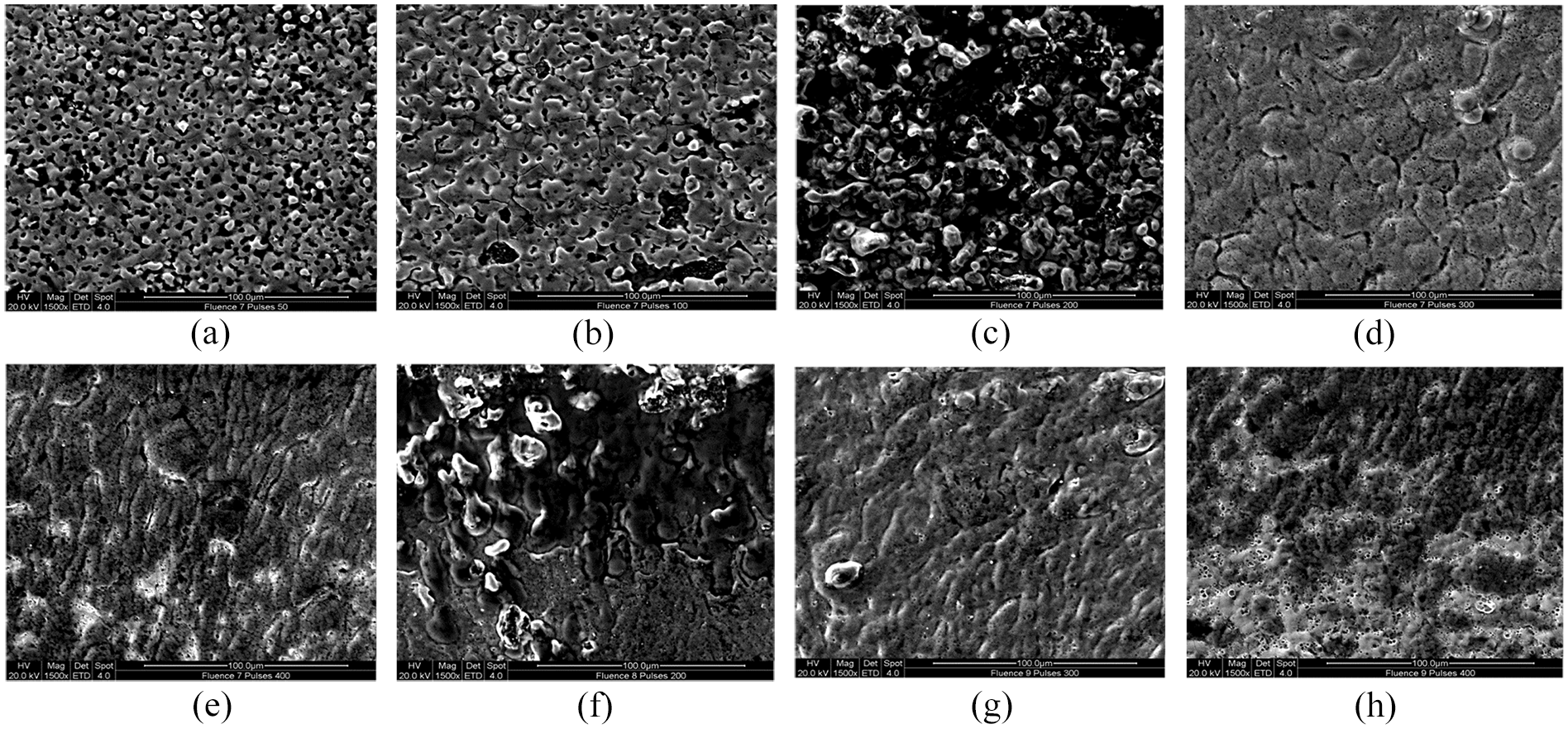
SEM images of laser irradiated area at laser parameter (a) 7 J/cm2, no. of pulse = 50, (b) fluence = 7 J/cm2, no. of pulse = 100, (c) fluence = 7 J/cm2, no. of pulse = 200, (d) fluence = 7 J/cm2, no. of pulse = 300, (e) fluence = 7 J/cm2, no. of pulse = 400,(f) fluence = 8 J/cm2, no. of pulse = 200, (g) fluence = 9 J/cm2, no. of pulse = 300 and (h) fluence = 9 J/cm2, no. of pulse = 400.
To confirm the removal of the coating layers, an elemental energy dispersive spectroscopy (EDX) line scan analysis was performed outside and within the stripped area. By scanning the beam and displaying the intensity of specific X-Ray line (denoted with point x and y) on the sample, the percentage count of element distribution was produced. Figure 6 illustrates how the measurement was conducted with some of the characteristics of the samples.
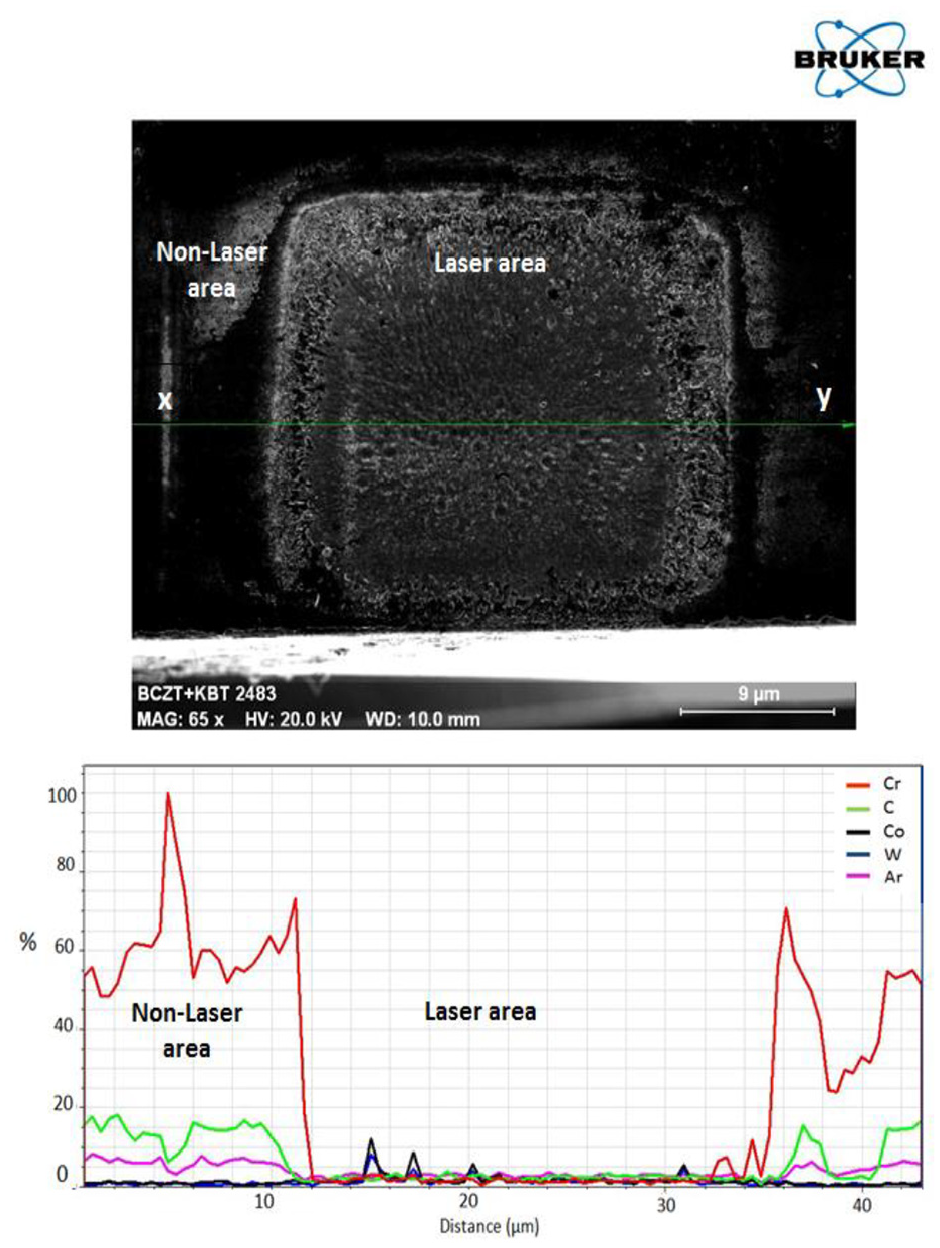
Elemental energy dispersive spectroscopy (EDX) line scan.
Analysis from the EDX spectrum shown in Figure 7 provides an in-depth explanation of the activities that occurred when the laser was administered on the workpiece. As for the DLC coating, the top layer of hard DLC coating started cracking at 50 to 100 number of pulses; however, at this lower pulse, the energy from the laser was not sufficiently strong to penetrate further into the bonding layer of the hard DLC coating. No significant change was recorded by the EDX line spectrum analysis as the pulses number increased to 200. In Figure 7(d) a noticeable drop of carbon elements percentage was captured at pulses number 300. Nevertheless, the traceability of chromium (Cr) adhesive layer in the EDX spectrum indicated that the ablation process was still incomplete. In Figure 7(e) the de-coating process using 400 number of pulses indicated the removal of the hard DLC layer as evidenced by the weight percentage count. It is notable that the level of chromium adhesive layer also dropped to almost zero to indicate the completion of the de-coating process. As illustrated in Figure 7(f), subsequent trials using 8 J/cm2 fluence with 200 number of pulses demonstrated that complete removal of hard DLC coating was achieved; however, the laser pulse energy was unable to go beyond the titanium film layer. Further increase in fluence and number of pulse resulted in damage to the WC substrates as shown in Figure 7(g) and (h).
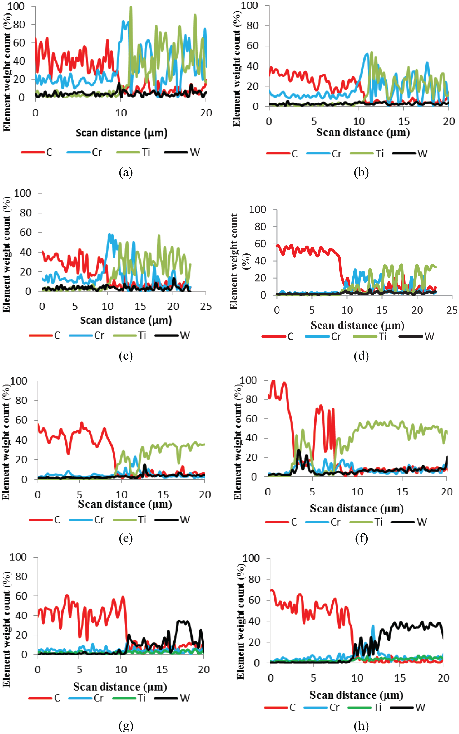
EDX line scan analysis at laser parameter (a) 7 J/cm2, no. of pulse = 50, (b) fluence = 7 J/cm2, no. of pulse = 100,(c) fluence = 7 J/cm2, no. of pulse = 200, (d) fluence = 7 J/cm2, no. of pulse = 300, (e) fluence = 7 J/cm2, no. of pulse = 400,(f) fluence = 8 J/cm2, no. of pulse = 200, (g) fluence = 9 J/cm2, no. of pulse = 300 and (h) fluence = 9 J/cm2, no. of pulse = 400.
Evaluation of surface textures on ablated spot
Apart from reaching 3.2 μm ablation depth, another successful criterion for the de-coating process is surface profile. The etched area has to present a good surface finish without any significant detrimental flaw. Typical surface profile for several laser conditions are shown in Figure 8(a)–(d) in which the texture of the un-laser insert is compared to the roughness that results from de-coating. In general, a relatively high average surface texture caused by the laser irradiation was captured. What also became apparent was that surface texture increased in tandem with a rise in fluence and pulse number. The increase in surface texture could be attributed to the evaporation mechanism in the laser process: when the laser was pulsed on the selected area, the heat generated was diffused to the underlayer coatings to create a molten area. At high fluence and pulse, there is a possibility of significant recoil pressure precipitated by a high degree of vaporisation which expel the earlier molten phase from the ablated area. Such interaction is likely to result in increased surface texture on the ablated area.
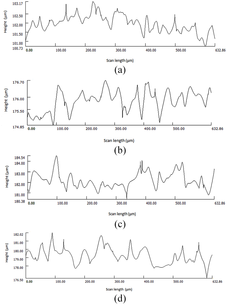
Line profile of surfaces showing the size of different surface features that be used to measure the surface roughness of (a) un-laser, (b) fluence = 2 J/cm2, number of pulse = 50,(c) fluence = 7 J/cm2, number of pulse = 400 and(d) fluence = 9 J/cm2, number of pulse = 400.
Conclusion
A method of de-coating hard DLC coating from tungsten carbide (WC) substrates using KrF excimer laser at the wavelength of 248 nm has been successfully demonstrated. From the range of laser parameters tested, fluence of 7 J/cm2 with frequency 25 Hz and the application of 400 number of pulses were found as the most optimum laser parameters to selectively de-coat 3.2 μm thick hard DLC coating. Operating beyond this specific laser fluence would irradiate TiCN+Al203 underlayer and possibly cause substantial damage to WC substrates. The none traceability of carbon re-deposition from the EDX line analysis suggested that evaporation is a possible mechanism to facilitate coating removal.
Footnotes
Acknowledgements
The authors would like to thank Teer Coatings Ltd and Kyocera Unimerco Ltd for technical support.
Declaration of conflicting interests
The author(s) declared no potential conflicts of interest with respect to the research, authorship, and/or publication of this article.
Funding
The author(s) received no financial support for the research, authorship, and/or publication of this article.