
Abstract
The pillow is a defect that adversely affects the geometrical accuracy as well as the formability in single-point incremental forming. With a main objective to control this defect, the effects of mechanical properties of material on pillowing are examined in this work. To identify the mechanical property that significantly affects pillowing, single-point incremental forming tests are conducted using a variety of materials (i.e. 11). It is found that a property (i.e. area reduction at tensile fracture) that controls the formability of a material in single-point incremental forming does not have any significant effect on its pillowing tendency. Interestingly, hardening exponent (i.e. a property that has controlling influence on the stretch-ability of material) appears to be the most influential property that determines the pillowing tendency of sheet metals in single-point incremental forming. Furthermore, the pillowing tendency of a material decreases with the decrease in this particular property. This, according to finite element analysis, occurs because strain localization around the tool/sheet contact correspondingly increases. To select and rank materials with respect to the pillowing behavior, a formula describing the property–pillowing relationship is proposed. As a secondary objective, the correlation between pillowing and forming depth is also investigated in this work. It is shown that initially the pillow progresses as the forming depth increases. However, after forming has been carried out to a certain depth, the pillow begins to regress, most likely due to strain hardening of sheet metal. In conclusion, it is suggested to lower the hardening exponent of sheet metals in order to control pillowing in single-point incremental forming.
Introduction
Single-point incremental forming (SPIF) is a process of converting a flat sheet-blank into a contoured shape through successive increments of deformation, which are imposed making use of a simple hemispherical-end cylindrical tool. The motion of the tool is controlled by a predefined trajectory, generated from the computer-aided design (CAD) model of the component to be produced. The process is assumed to belong to the metal spinning family. 1 However, unlike spinning, it does not employ any counter mandrel to form a part. Moreover, contrary to spinning, the SPIF process can also perform asymmetric forming besides axisymmetric. Owing to these characteristics, the process has potential to replace not only spinning but also press forming, a group of classical sheet forming operations characterized by high tooling cost and long lead time.
In addition to simplicity, the higher formability compared with that of conventional pressing is another interesting and promising aspect of SPIF. Shim and Park 2 and Allwood et al. 3 have proposed the localized deformation and through-thickness shear as the major reasons of the increased forming limits of SPIF process, respectively. As far as the capability to process different materials is concerned, SPIF can deform almost all types of ductile materials including metals.4–8 To attract the manufacturers’ attention, several industrial applications (e.g. car-body panels, customized leg and dies) of the process have been demonstrated in the literature.9–11 More details on the applications and advances made in the process have been provided in review articles by Jeswiet et al. 12 and Echrif and Hrairi. 13
Where SPIF offers benefits, it also suffers from serious drawbacks of slow forming speed, poor profile accuracy and defects which question the industrial viability of the process. The latest efforts reported in Ambrogio et al. 14 have shown that the issue of slow speed can be overcome by employing high-speed incremental forming equipment (i.e. computer numerical control (CNC) turning center). The subject of accuracy has been addressed in Ambrogio et al., 15 Bambach et al., 16 Hussain et al., 17 Malhotra et al., 18 Verbert et al., 19 Duflou et al. 20 and Allwood et al. 21 According to these studies, the accuracy can be improved by modifying tool path, optimizing parameters, employing multi-stage forming, using counter tool, introducing feature-based approach, laser heating and making holes in the blanks, respectively. The last issue of defects has been lately studied by the authors of this work to introduce three defects, namely, wall, back-fold and pillow.22,23 To minimize these defects, they suggested to process sheet metals with optimal parameters. Hot forming has been proposed as an alternative approach 24 to control the last of the aforementioned three defects. However, adaptation to this method will not only increase the product cost but also adversely affect the strength of formed component and the process simplicity, a salient feature of SPIF.
The pillow, as schematized in Figure 1(a), is an SPIF defect which develops due to the bulging of sheet-blank while forming a part (say cone). In our previous study, 23 it was experimentally demonstrated that excessive pillowing, besides profile accuracy, causes premature sheet fracture especially at low wall angles (say 20° as depicted in Figure 1(b)). Consequently, the forming limit, which is usually defined as the maximum wall angle without sheet fracturing, reduces to a range between the maximum and minimum wall angle (i.e. θmax−θmin). In an attempt to overcome pillowing, the effects of some process parameters were investigated, and it was found that tool diameter is the principal parameter that can control pillowing. Finally, it was proposed to employ large-size tools to reduce pillowing. The study of the reason of this finding, however, was left for future.
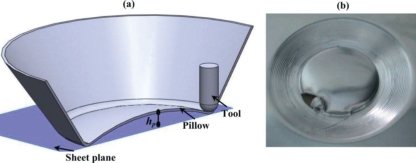
(a) Schematic of pillow in the cone geometry and (b) sheet rupturing due to pillow. 23
This study has been primarily undertaken to propose an alternative solution to control pillowing through controlling material properties. A limited amount of work to identify the most influential property was performed earlier using one material, that is, Aluminum AA1060.22,23 To vary the material properties, the test material was cold rolled to three different levels. As a result, the material strength increased, while the ductility and hardening exponent decreased correspondingly. Due to this reason, the material property controlling pillowing in SPIF could not be clearly identified. Therefore, further work using various materials needs to be carried out. To do so, a number of SPIF tests using 11 different materials with a variety of physical conditions obtained by employing work-hardening and heat treatment processes are conducted. And a general correlation between the size of pillow and the most influential property is established. As a secondary objective, investigations into the effect of forming depth on pillowing are also carried out. Furthermore, an attempt is made to find the cause of a previous finding that was left as future work (i.e. the size of the pillow reduces as the tool diameter increases 23 ). To know the mechanisms for the experimental results and to fulfill the aforementioned future work, the finite element analyses (FEAs) are performed. As a result of this study, the role of mechanical properties on the pillowing tendency of materials has become clarified. Thus, an alternative solution to control pillowing in SPIF has been revealed.
Experimental and FEA procedures
Table 1 presents the mechanical properties of 11 different materials employed in this study. As can be seen, materials with a variety of conditions were chosen so that generalized conclusions could be drawn. Of these materials, one is tempered, two are work hardened and the rest are in annealed condition. This selection provides a wide range of mechanical properties such as the yield strength from 54 to 296 MPa, the percent elongation from 5.5% to 63%, the hardening exponent from 0.04 to 0.53 and the percent reduction in area at tensile fracture from 24.7% to 81.5%.
Average mechanical properties of sheet metals and the corresponding pillow height.
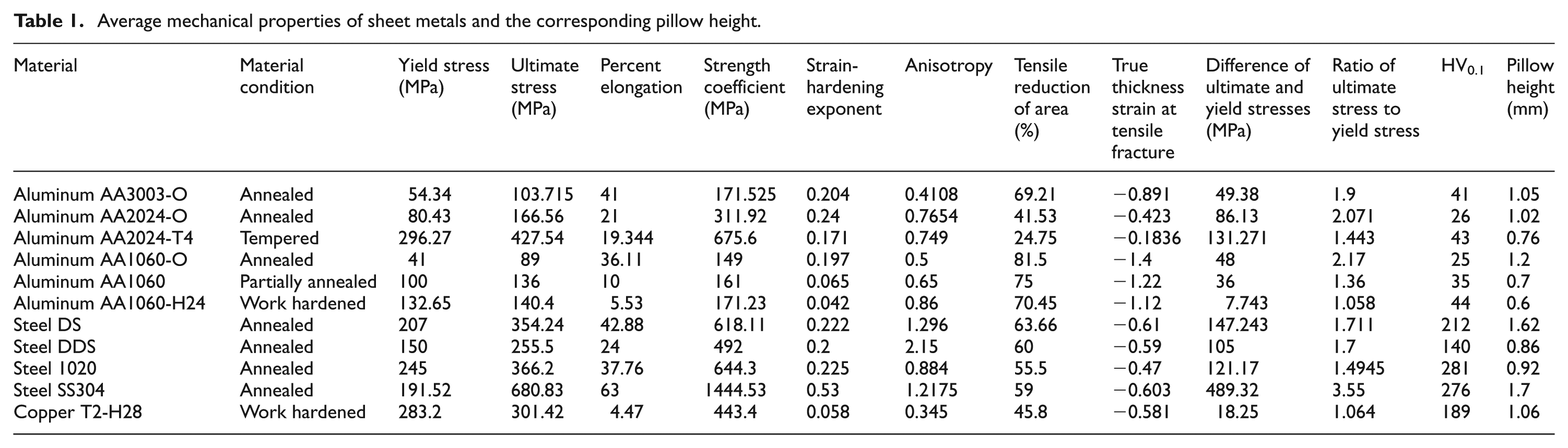
To determine the mechanical properties of materials, the uni-axial tensile tests were performed. The test specimens (three samples along each of 0°, 45° and 90° to the rolling direction of sheet) with 50 mm gauge length and about 1 mm sheet thickness were cut, according to ASTM E8 standard, on a CNC milling machine. The tensile tests were conducted at the cross-head speed of 2 mm/min with an MTS 810 tensile testing machine. In addition to tensile tests, the hardness tests were also performed using a Vickers hardness tester to clarify the influence of metal hardness on pillowing, if any. The various mechanical properties were determined following the well-known procedures detailed in the international literature.
For the sake of simplicity, the frustum of cone with major diameter of 110 mm was employed as the test geometry. To investigate the effect of mechanical properties on the pillowing tendency, the wall angle and the depth of frustum were kept constant at 20° and 10 mm, respectively. However, in order to determine the influence of forming depth, the depth of test specimen was varied from 2 to 18 mm. To examine the correlation of mechanical properties with the pillowing tendency, 1-mm-thick sheets were used. But for the rest of tests, sheet with 3 mm thickness was employed. The other parameters were set fixed as follows: step size = 0.8 mm, tool diameter = 8 mm and feed rate = 3 m/min. For all materials, except stainless steel, the mineral oil was used as the lubricant. For stainless steel, to reduce galling, an aqueous suspension of graphite was employed as a lubricant. In order to provide statistical means, at least two replicates were produced for each test. The pillowing tendency of the material (or part) was defined as the maximum height of pillow (hp) as indicated in Figure 1(a). The pillow height in each test was measured from the center of part’s bottom, using a depth gauge, with an accuracy of ±0.01 mm.
The FEAs were performed using a commercial FE package LS-DYNA. The sheet discretization was done using shell elements with (1 × 1) mm size of each element. The simulations were carried out with comparatively large feed rate (i.e. 15 m/min), as compared to 3 m/min employed in the physical tests, so as to reduce runtime. 25 The coefficient of friction, which was experimentally determined employing pin on a disk apparatus, was set as 0.12. The other parameters were set to the same values as adopted in the experiments. The necessary mechanical properties required for the FEAs were obtained from Table 1.
Results and discussion
Effect of mechanical properties on the pillowing tendency in SPIF
In Hussain et al., 6 it has been shown that the percent reduction in area at tensile fracture (a mechanical property) is a general indicator of formability in SPIF (i.e. spif-ability). This finding dictates that besides having controlling influence on the formability, the said property might also control pillowing tendency of materials in SPIF. Therefore, in an attempt to identify the most influential property, the correlation of percent reduction in area at tensile fracture with the pillow height (i.e. hp) was examined to begin with. It can be seen from Figure 2(a) that the datum points are randomly scattered, interestingly revealing that the formability indicator of SPIF does not constitute any meaningful relationship with the pillow height. However, a thorough observation of Table 1 shows that it may be used to rank the condition of a particular material with respect to the pillowing tendency. For example, as can be noticed from Table 1, when the condition of AA1060 alters from annealed to work hardened (i.e. AA1060-O to AA1060-H24), the percent reduction in area decreases from 81.5% to 70.45%, and correspondingly the pillow height decreases from 1.2 to 0.62 mm. Likewise, the pillow height of AA2024 in the annealed state (percent reduction in area = 41.53%) is higher than that in the tempered state (percent reduction in area = 24.75%). Nonetheless, as obvious from Figure 2(a), the percent reduction in area does not form general relationship with the pillow height, and therefore, it cannot be employed as a pillowing indicator (or to rank different materials) of the overall SPIF process. The same applies to the fracture strain in tension test (Figure 2(b)), the second property reported to be significant with respect to the influence on the spif-ability in Hussain et al. 6 Hence, it can be said that none of the two formability indicators of SPIF can be used as a general indicator of pillowing behavior of materials in SPIF.
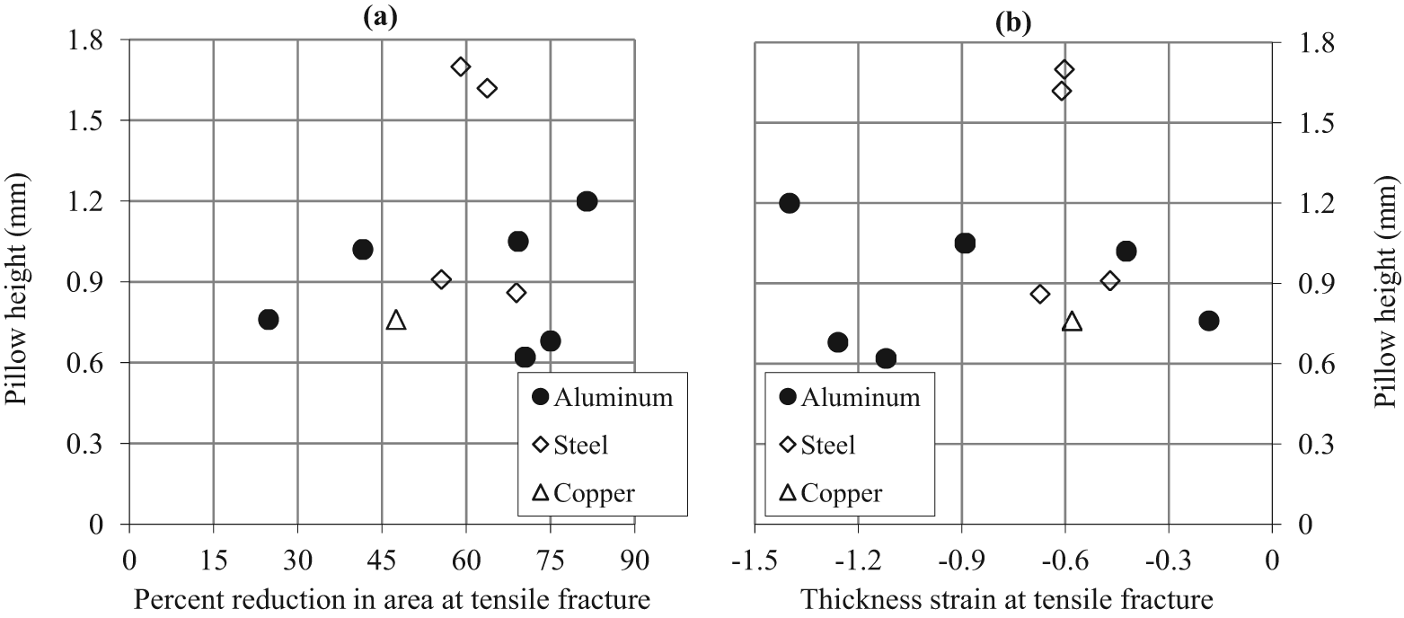
Correlations of (a) percent reduction in area at tensile fracture and (b) thickness strain at tensile fracture with the pillow height.
To find out the most appropriate property affecting pillowing in SPIF, the correlation of each of the remaining mechanical properties, listed in Table 1, was examined against pillow height. Based on R2 value (multiple correlation factor), it was found that no relationship exists between the pillow height and quantities such as anisotropy, hardness, ultimate tensile stress and even yield stress, which determines the initial yielding of a material, as evidenced in Figure 3. However, the hardening exponent and percent elongation constitute fairly consistent relationships with the pillow height, as depicted in Figure 4. Though the latter can also be employed, the former being larger in R2 value seems to be more reasonable candidate as a pillowing indicator in the SPIF process. It is to be noted down that the hardening exponent, consistent with Hussain et al. 6 , does not constitute any meaningful relation with the formability in SPIF. But, as found herein, it has amazing controlling influence on the pillowing tendency of materials in SPIF.
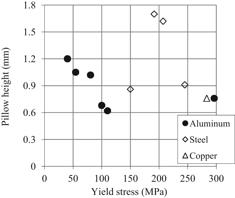
Correlation of yield stress with the pillow height.
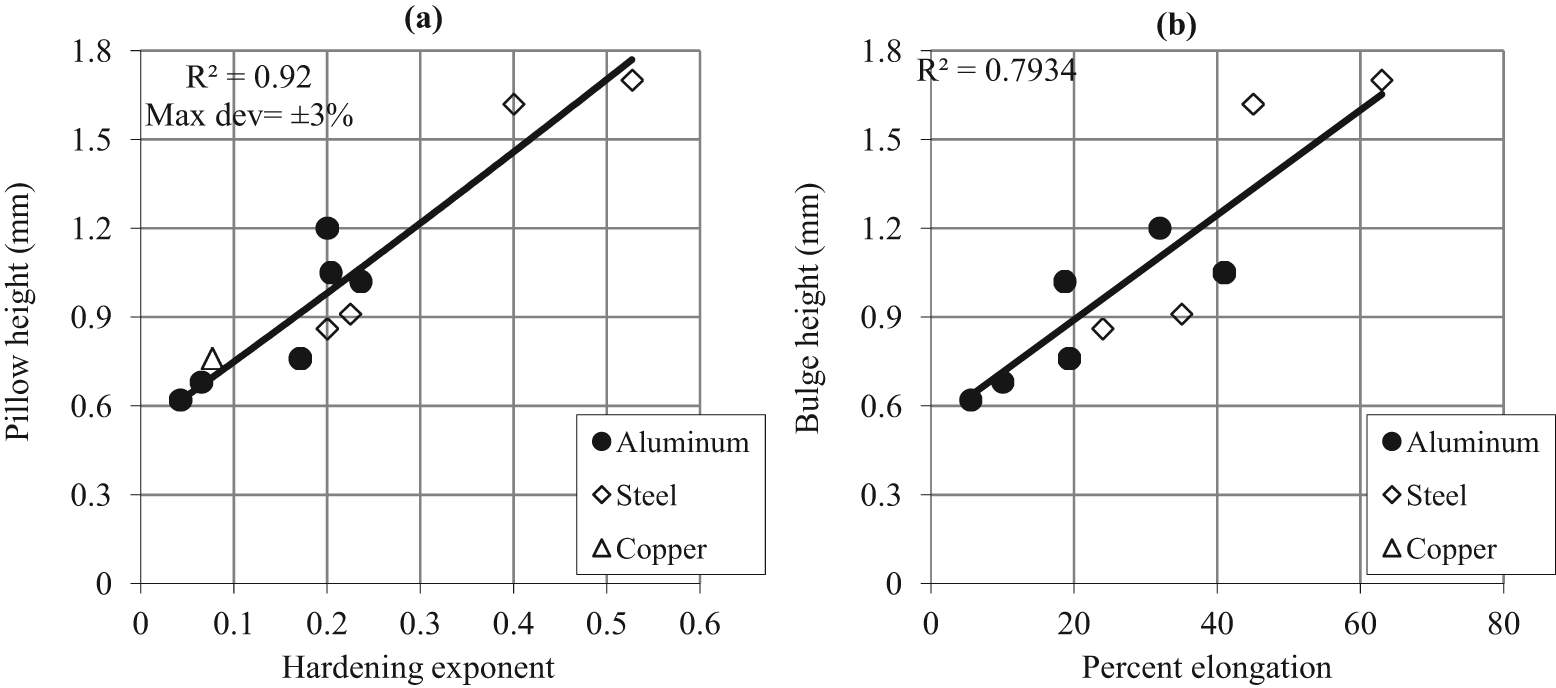
Correlations of (a) hardening exponent and (b) percent elongation with the pillow height.
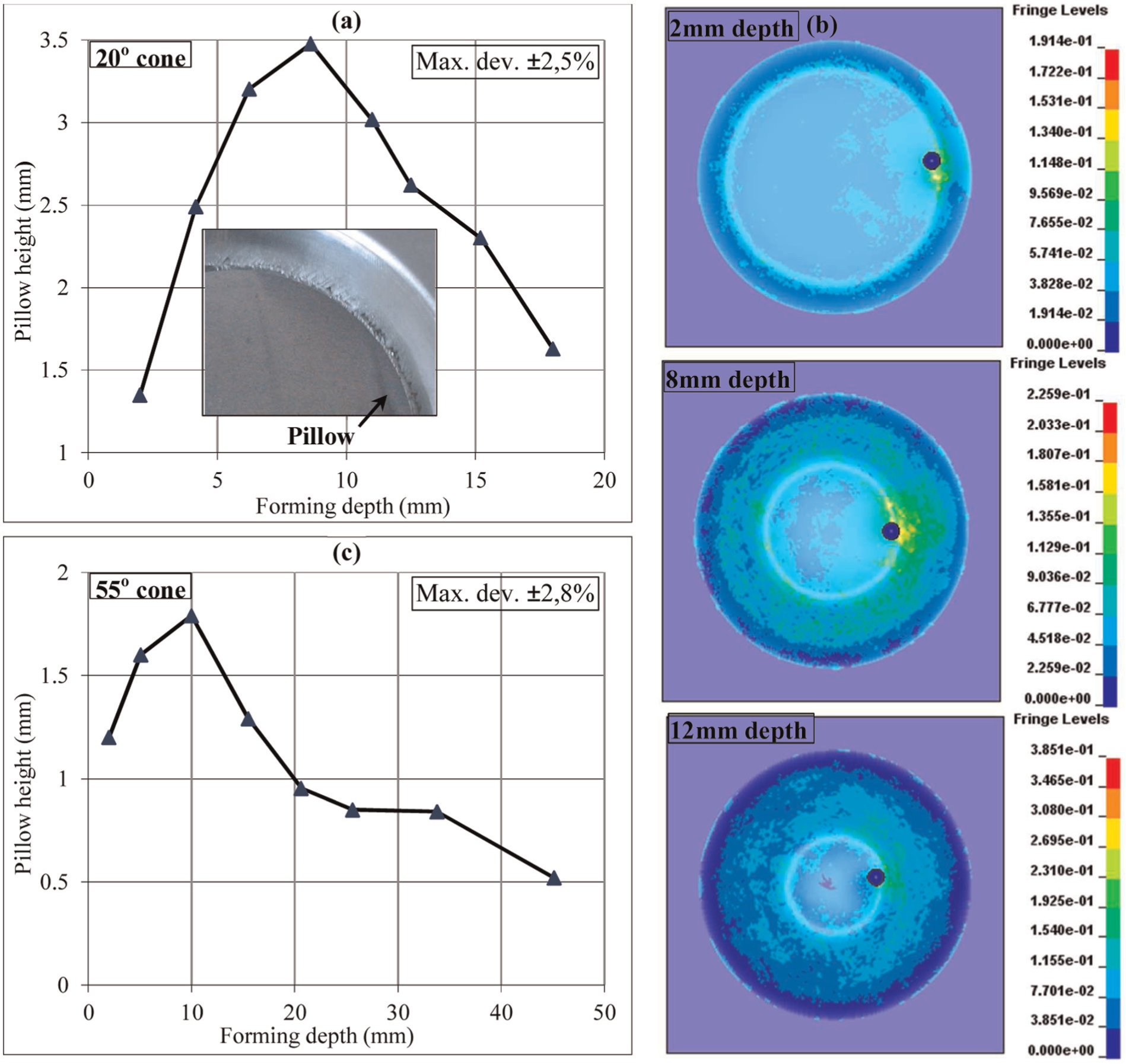
The pillow height, as can be seen from Figure 4(a), linearly increases with the increase in hardening exponent, and it can be related to the hardening exponent through the following empirical formula
where hp is the pillow height and n is the hardening exponent. The R2 value for the above formula is about 92%, which confirms that the data points are well fitted to the formula’s curve. Therefore, the formula can be reliably employed to estimate the pillow height of a material by knowing only one of its several properties (i.e. hardening exponent). Though the formula provides exact estimation for the investigated conditions, it can be used for a general purpose to rank the materials with respect to the pillowing behavior and thus will facilitate the material selection to design pillow-controlled products.
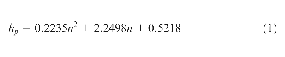
In order to further clarify the role of hardening exponent on pillowing, the relevant mechanism needs to be clarified. However, to do so, first it is necessary to know why pillowing of sheet occurs specifically when the deformation in SPIF is commonly acknowledged to be extremely localized. For this purpose, the von Mises stresses (a representation of total stress state) on the pillow site of two cones with the hardening exponent of 0.04 (AA10160-H24) and 0.24 (AA2024-O), respectively, were analyzed as shown in Figure 5(a). It can be seen that the von Mises stresses are widely distributed over the pillow site, indicating that the formation of pillow is actually an outgrowth of stresses caused by sheet deformation beneath the SPIF tool. It also highlights that although the SPIF deformation is local and remains confined to the tool/blank contact area, as claimed in the literature, 2 the repercussion of this deformation (i.e. the effect of deformation stresses) is not local.
Effect of variation in the hardening exponent on (a) strain distribution and (b) von Mises stresses.
Returning to the earlier discussion regarding the influence of hardening exponent on the pillowing tendency of sheet-blank, plastic strain on the pillow surface (or site) was analyzed for two materials with the hardening exponent of 0.04 and 0.24, respectively. It was observed that the surface strain on the pillow in either of the cases was tensile (positive) in nature, as demonstrated in Figure 5(b), which proposes that a pillow is most likely an outcome of sheet bulging that of course is caused by the SPIF stresses as discussed before and evidenced in Figure 5(a). To find the reason why an increase in the hardening exponent promotes pillowing, two points (A and B, respectively, one in the tool/blank contact and the other in the center of pillow as indicated in Figure 5(b)) on the pillow surface were selected in each case (i.e. cones with 0.04 and 0.24 exponents), and the strain analysis was conducted. It was noticed from the strain fields that the strain in the cone with the exponent of 0.04 (pillow height = 0.54 mm) was relatively restricted around the tool/blank contact zone (see Figure 5(b)): its magnitude in the cone’s center was very small (i.e. εB≈ 1/5εA, where ε stands for strain). Whereas the strain in the other cone having the exponent of 0.24 (pillow height = 1.1 mm) was largely distributed over the bottom (i.e. εB≈ 1/2εA). This finding reveals that a sheet with a high exponent undergoes more pillowing because the material ability to undergo uniform deformation in response to the applied stress increases (or strain localization around the local deformation zone decreases). This role of hardening exponent on pillowing tendency of material is in agreement with its role on stretch-ability of the material reported in Hosford and Caddell. 26 From here, it follows that there might be a similarity between the pillowing and stretching mechanisms. Furthermore, in view of role of exponent on pillowing and that of area reduction on the formability in SPIF, the sheet deformation underneath the tool and away from the tool/sheet contact zone seems to be governed by different mechanisms. Further discussion on this point requires extensive experimental and FEAs which will be performed in future.
Summarizing the discussion, as an alternative to the strategy proposed in Malhotra et al. 18 (i.e. to employ large-size tool), pillowing in SPIF can be reduced (or controlled) by decreasing the hardening exponent of material. This task can easily be accomplished through cold rolling process. Furthermore, doing so will not significantly affect the material formability because it mainly depends on the percent reduction in area at tensile fracture rather than on the hardening exponent. 6 For example, according to Hussain et al., 6 80% reduction in the hardening exponent (0.2 to 0.04) of AA1060 aluminum sheet (1 mm thick) causes only 4% reduction (82° to 79.5°) in its formability which compared to a large decrease (i.e. 50%) in the pillow height is minimal (i.e. 1.2 to 0.6 mm as given in Table 1). This is worth noting that cold working is known as a method of enhancing fatigue strength of materials. This means that using a cold worked material, one can simultaneously overcome the pillow defect as well as can improve fatigue strength of components without considerably sacrificing the formability, which contrary to classical processes can be considered as an additional promising aspect of the SPIF mechanics.
Progression of pillow with forming depth
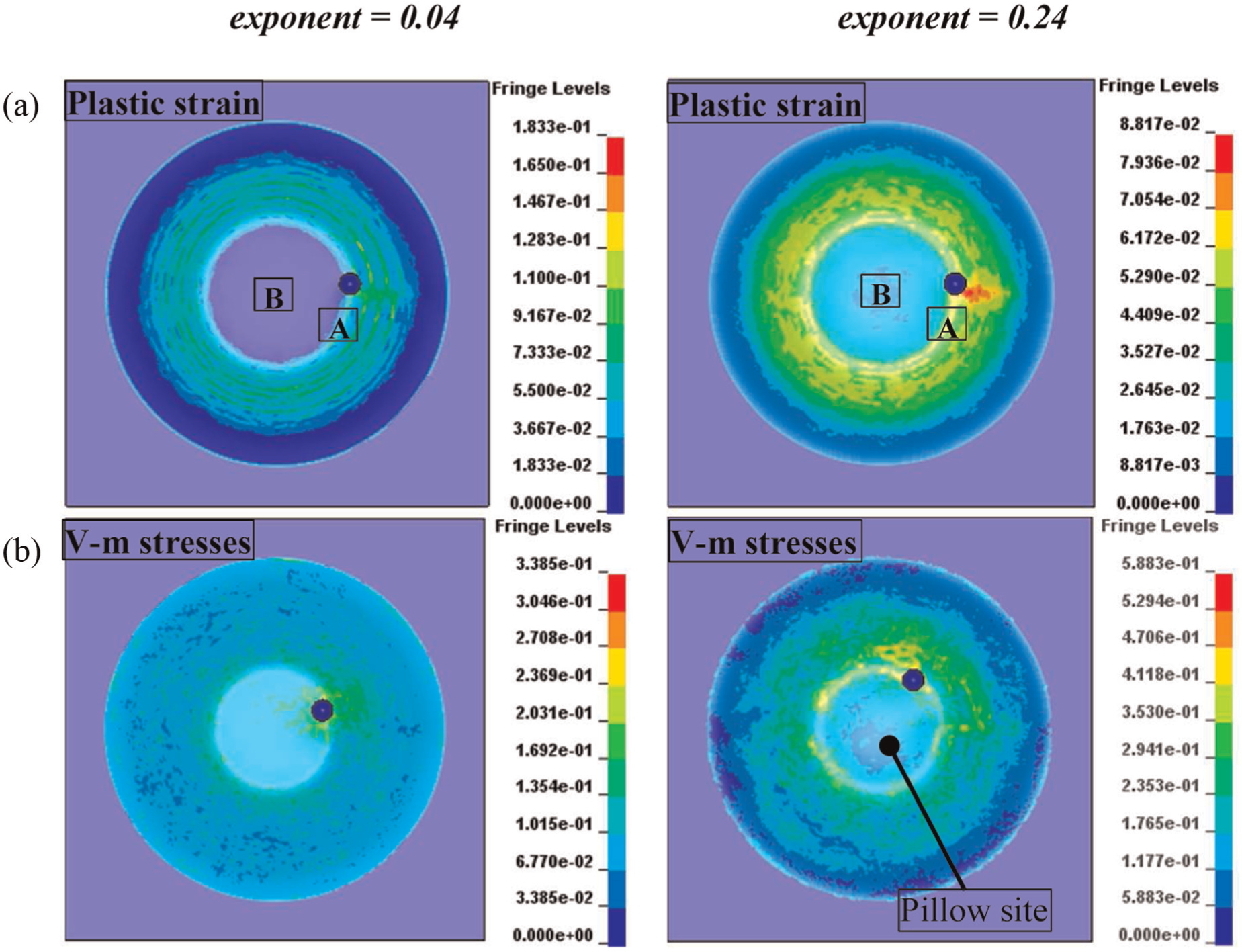
Figure 6 exhibits the progression of pillow defect with varying forming depth. As can be seen from Figure 6(a), the height of pillow increases from 1.35 to 3.5 mm as the forming depth of 20° cone is increased from 2 to 9 mm. However, further increment in the depth after 9 mm (from 9 to 18 mm) contrarily leads to reduction in the pillow height (from 3.5 to 1.62 mm). In fact, as can be seen from the contours of von Mises stresses given for 2, 9 and 18 mm forming depths (Figure 6(b)), the stress level of sheet metal in the part’s bottom rises with each incremental loop of forming (compare stresses in the part’s bottom for various depth values), which in turn causes the strain hardening of sheet. It seems that the increase in the pillow height with increase in the forming depth from 2 to 9 mm is due to increase in sheet bulging because of the said rise in stresses. The decrease in the pillow height with the increase in forming depth, however, can be attributed to the effect of high strain (or stress) hardening of sheet material in the part’s bottom (i.e. the hardening exponent decreases significantly), which in this case seems to occur when the part has acquired 9 mm depth. The sheet material after attaining a certain level of hardening (i.e. after 9 mm forming depth) does not (or comparatively minor) further bulge out in the following loops of forming. On the other hand, to produce the required forming depth, the SPIF tool continues to consume pillowed-sheet available in the bottom. As a result, the pillow height reduces with each succeeding increment from 9 to 18 mm. Similar trend, like the one in Figure 6(a), has been observed under varied process conditions: for example, with wall angle of 55° as evidenced in Figure 6(c). This is to be noticed from Figure 6(a) and (b) that the pillow in both 20° and 55° cones attains the maximum height corresponding to about 10 mm depth (i.e. same depth). This information may prove helpful for the process and product designers.
(a) Progression of pillow with the increase in forming depth in 20° cone, (b) distribution of von Mises stresses with varying forming depth and (c) progression of pillow with increasing forming depth in 55° cone.
As mentioned earlier, after the sheet has been formed to a certain depth, the pillow due to strain hardening begins to regress when forming is further carried out to increase the part (or forming) depth. This observation endorses the above finding that the pillowing tendency of a material decreases as the hardening exponent decreases; a clearer evidence of this observation can be seen from Figure 6(c) where the said trend continues over a relatively wide range of depth (i.e. from 10 to 45 mm). Ambrogio et al. 15 have shown that the discrepancy between the actual and experimental profiles varies as the depth of a part varies. The results presented in Figure 6 indicate that this is because of the variation in the stress level and pillow height.
Observations on the effect of tool diameter on pillowing
According to earlier investigations, 23 tool diameter is the most influential operating parameter on pillowing in SPIF. Furthermore, the pillowing can be reduced by increasing the tool size. In order to know the reason of this finding, SPIF of 55° cone with 3-mm-thick sheet was simulated for the two levels of tool diameter (i.e. 8 and 20 mm), and the stress components in the sheet plane (σx, σy) and normal to it (σz) were analyzed. It was found that the nature of σz in zone B (pillow center) altered from tensile to compressive, as evidenced in Figure 7, as the tool diameter was increased from 8 to 20 mm. As a result, a corresponding decrease in the pillow height (from 1.1 to 0.6 mm) was observed when measured from the software. These results point out that a large-size tool (say 20 mm) regresses pillowing because it, owing to comparatively higher contact area with sheet than a small tool (say 8 mm), imposes compressive stresses in a direction normal to the sheet plane: more information on the role of tool size on pillowing has been detailed in the previous study. 23
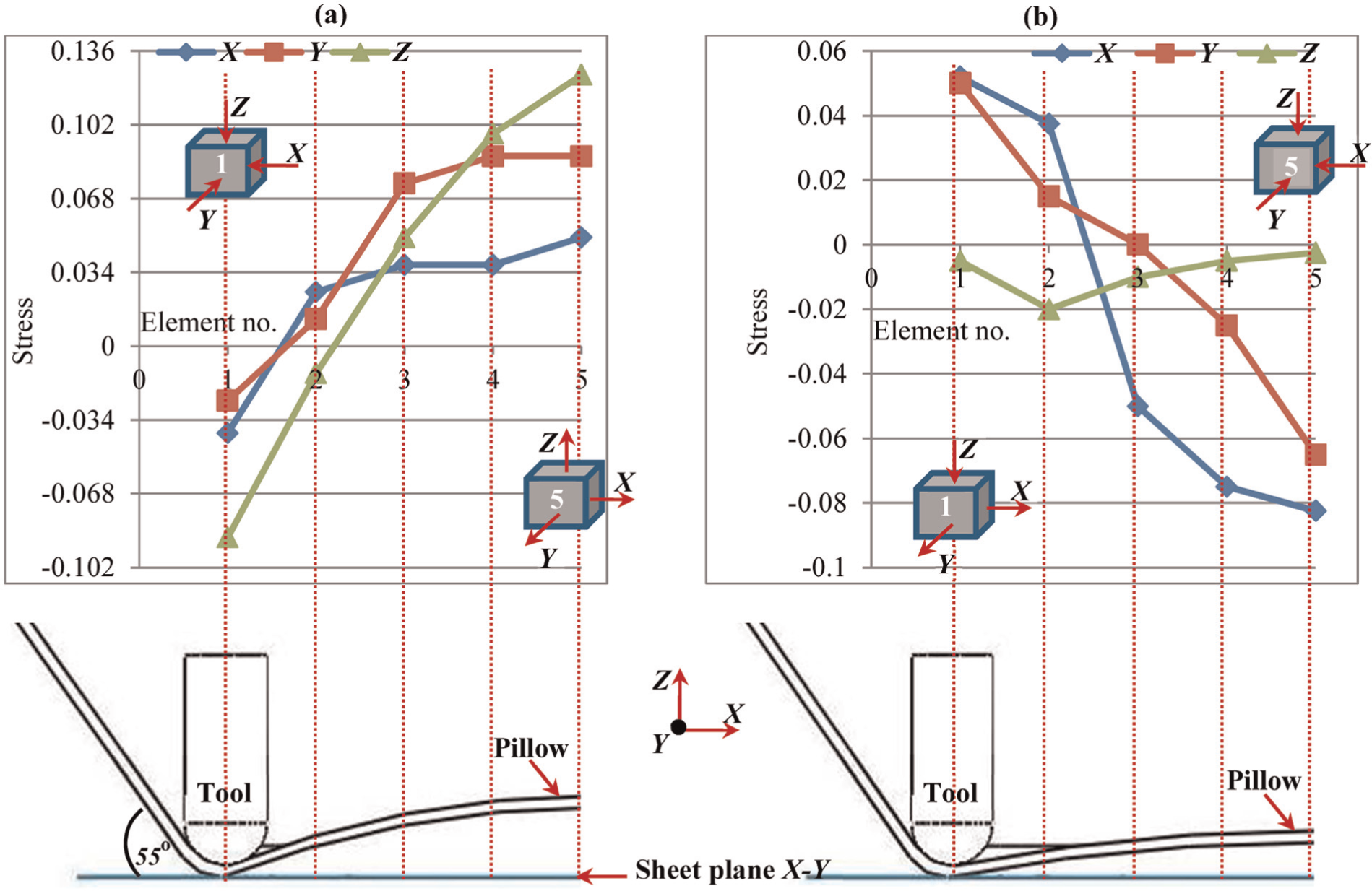
Distribution and nature of stress at varying tool diameter: (a) d = 3.5to and (b) d = 4.5to.
According to the previous 23 and current studies, there are two options to control pillowing: by increasing the tool diameter and by lowering the hardening exponent through cold working of material. The stress–tool size relation discussed above and presented in Figure 7 indicates that a change in the shape of tool-end from spherical to flat could serve as a third option. Because a flat-end tool being entirely in contact with the sheet comparative to spherical-end tool may impose more compressive stresses (i.e. σz) than a spherical-end tool does. Ziran et al. 27 have performed a small piece of work in this direction to show that flat-end tool diminishes pillowing, comparative to spherical-end tool, in SPIF. However, the work was limited to a narrow U-channel shape and also no scientific mechanism was provided. Hence, further FEA-based investigations are required to thoroughly investigate this theme.
Conclusion
This study was undertaken with a primary objective to overcome pillowing in SPIF by controlling the properties of material. To fulfill this purpose, the most influential property was identified by plotting pillow height with various properties of 11 materials. The relationship between the forming depth and pillow size was also investigated as a secondary objective. Besides these two objectives, some observations to know the cause of a previous finding (i.e. pillow size decreases as the tool diameter increases) were made as well. In addition to doing tests, the FEAs were also performed in an attempt to know the reasons of empirical results. The important findings of the study are summarized as follows:
The mechanical property that controls the spif-ability of a material (i.e. reduction in area at tensile fracture) does not have any significant effect on its pillowing tendency in SPIF. The hardening exponent (i.e. stretch-ability indicator) on the other hand shows controlling influence on pillowing and establishes a consistent relationship with the pillow height. Therefore, the hardening exponent can be used as a pillowing indicator of materials in the SPIF process.
The analyses of stress and strain distributions on the pillow site of parts show that the development of a pillow is an outgrowth of deformation stresses of SPIF tool. This points out that although the deformation imposed by the SPIF tool is local, its after-facts are not localized.
The height of pillow decreases as the hardening exponent of a material decreases. This, as found from the FEA, is because of the fact that the strain localization around the deformation zone (i.e. tool/sheet contact vicinity) correspondingly increases. Therefore, pillowing in SPIF can be controlled by lowering the hardening exponent of material which can be done through cold working.
The relationship between the pillow height and the hardening exponent is defined by a linear formula. One by knowing only one property can use this formula to rank the materials with respect to the pillowing behavior and hence can select an appropriate material (or condition) to produce pillow-controlled components.
As the forming depth increases, the stress level in the sheet material in the part’s bottom increases which consequently promotes pillowing. However, this trend continues till a certain depth (say 9 mm for the present case) of part where the pillow achieves the maximum height. Henceforth, strain hardening of sheet occurs and the pillow begins to regress in the following loops of forming.
The FEA conducted to know the effect of tool diameter on pillowing (future work of Hussain 23 ) has revealed that the pillowing decreases with the increase in tool diameter because the nature of normal stress (i.e. stress normal to sheet plane) correspondingly shifts from tensile to compressive.
Future work
The benefits of using flat-end tool to reduce pillowing in SPIF and the related mechanisms will be witnessed by conducting detailed investigations.
Footnotes
Acknowledgements
The authors acknowledge with thanks the help provided by King Abdulaziz University for this research.
Declaration of conflicting interests
The authors declare that there is no conflict of interest.
Funding
This research was supported by King Abdulaziz University.