
Abstract
Single point incremental forming is a cost-effective alternative of conventional stamping process. However, due to inadequate knowledge, the process has not yet been employed on industrial scale. In this study, the role of tool radius in causing and controlling development of defects in single point incremental forming is investigated. Throughout the course of investigations, AA1060 aluminum is used as the experimental material. Initially, a range of tests with tool radius (r) ranging from 1to to 2.35to (where to is sheet thickness) are conducted. It is found that defects, namely, pillow, wall and material-fold, develop in a part if forming is performed with an unduly small tool (i.e. r<2to). Furthermore, as a result of these defects, the part accuracy and sheet formability reduce. In the second stage, the effect of selected process parameters (i.e. feed rate, yield strength, wall angle, sheet thickness and step size) on the growth (or size) of aforesaid defects is examined. The test results reveal that the investigated parameters, excluding feed rate, are significant. In order to prevent inappropriate selection of tool and thus to simultaneously control all the defects, a least-radius limit is defined (i.e. rl), and as a last stage of investigations, its correlation with the short listed significant parameters is determined. To do so, a comprehensive design of experiments is performed. According to the design of experiment findings, the radius limit rl varies as a process parameter is varied. Moreover, this variation effect of parameters is highly interactive. Finally, an empirical formula to predict the said radius limit is proposed and its correctness is verified.
Introduction
The recent changes in the pattern of customer’s demands require the manufacturers to produce components in small batches. However, the conventional pressing operations due to high capital cost are economically viable only for large-scale production. Therefore, in order to satisfy the innovative demands of market, a great deal of efforts to develop flexible forming methods has been made in the last decade. As a result of these efforts, many new forming processes such as hydroforming,1–4 laser forming, 5 water jet forming, 6 dimple forming 7 and single point incremental forming (SPIF) 8 have been introduced. SPIF being simple and highly flexible, however, has gained the greatest popularity among all. The process is capable to form metallic as well as polymeric materials.9–11 Due to these salient features, it has found several applications in aerospace, biomedical and automotive industries.12–14
Figure 1 shows the schematic and terminology of SPIF process. A sheet blank with initial thickness to is held in a rig. A hemispherical tool with the end radius r imposes deformation on the blank in a series of successive loops. In each loop, after depressing the sheet downward through an increment p, the tool traverses blank with feed rate f. The accumulative deformation from these loops results in desired shape with required depth h. Since the deformation in SPIF is mainly performed by stretching and shearing,15–17 the thickness of material reduces from to to t, often related as follows: t = to sinα = to cosθ, where to is the initial thickness of sheet material, t is the material thickness after forming, α is the cone angle and θ is the angle that the part’s wall makes with the horizontal axis (see Figure 1). As can be seen from the relation, the thickness of a part in SPIF mainly depends on its wall angle. Therefore, there is a limit on forming maximum value of this angle. This maximum limit of wall angle without sheet fracturing represents the formability in SPIF and is denoted as θmax.18,19 For further details on the process, the reader is referred to a review article by Echrif and Hrairi. 20
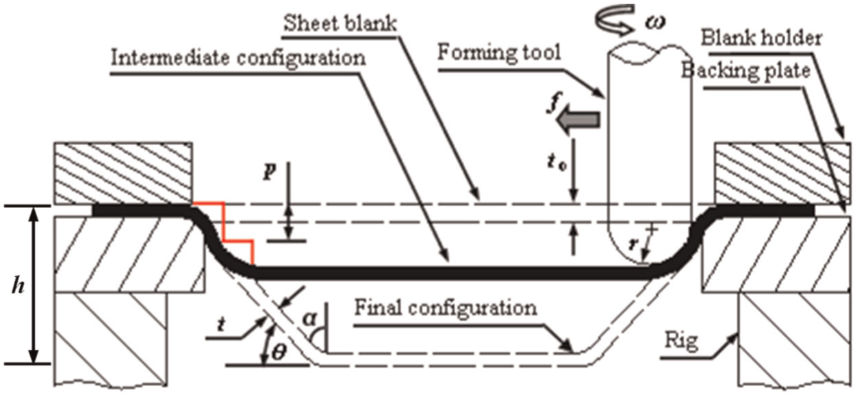
Schematic representation and terminology of SPIF process.
Despite owing numerous promising features, the SPIF process has not been widely adopted in industry. This is most probably due to the fact that the process suffered from some serious shortcomings, such as poor accuracy and defects. A couple of researchers have made attempts to rectify these flaws,20–22 a summary of which is given as follows. Otegi et al. 21 identified a defect called pillow, an outgrowth of bulging of material in the bottom of a part (see Figure 1). They found that the development of this defect induces error in the designed profile, and thus, it adversely affects the usefulness of part if its size is too large. To control this defect, they proposed a down-up forming strategy. Duflou et al. 22 suggested an alternative approach of hot forming in which they made use of laser heating to diminish this defect. These approaches are either time-consuming or costly. Ambrogio et al. 23 adopted a comparatively simple approach of parametric optimization to overcome pillow and related profile inaccuracy. They, without considering the thickness factor, reported that overall error in a part’s profile can be diminished by reducing tool size. A detailed examination of their test plan (Table 1) shows that the range over which the tool size was varied is very narrow to properly understand its effect on sheet deformation and hence on profile accuracy.
Levels of tool size and sheet thickness employed in Ambrogio et al. 23 and in this study.
A thorough deliberation into the tool/sheet contact in SPIF reveals that the selection of tool size in particular reference to sheet thickness is very important. The tool might not thoroughly depress the sheet if its size is very low and will consequently cause error in the part’s profile. In order to clarify this point, systematic investigations were carried out in this study. To begin with, the influence of very low tool size on the deformation behavior of material (i.e. AA1060 aluminum) was examined. This preliminary investigation led to a conclusion that two new defects (wall and material-fold), in addition to pillow, develop if a tool with size less than a certain limit is employed. Later, the relationship of the said tool-size limit with the process parameters was investigated. To do so, a comprehensive design of experiments (DoE) was conducted.
Material behavior in SPIF with very small tools
Table 1 presents the levels of tool radius and sheet thickness, as Ambrogio et al. 23 employed. As can be seen, the tool radius ranges from 6to to 9to. The high limit seems satisfactory; however, the low limit in view of earlier discussion is not sufficient to thoroughly understand the role of tool size on material deformation and hence on part’s profile. Therefore, further tests with comparatively low tool radii (i.e. from 2.35to to 1to) were performed (see Table 1). The profile error and sheet formability were treated as the responses of tests. The pyramid with 110 mm base size was opted as the test geometry, same as used by Ambrogio et al. 23 The AA1060 aluminum sheet, contrary to AA1050, 23 was employed as the experimental material. The tests were performed by systematically varying wall angle from 19° to 85° and by keeping the other parameters fixed as listed in Table 2. The effect of tool radius on part’s profile was examined by measuring (±0.02 mm accuracy) the profiles of 55° pyramids adopting the method reported in Ambrogio et al. 23 The formability was determined by changing the wall angle in small steps until the test specimen (i.e. pyramid) with an extreme wall angle (both minimum and maximum) had been formed without fracturing. The results of these tests are discussed below.
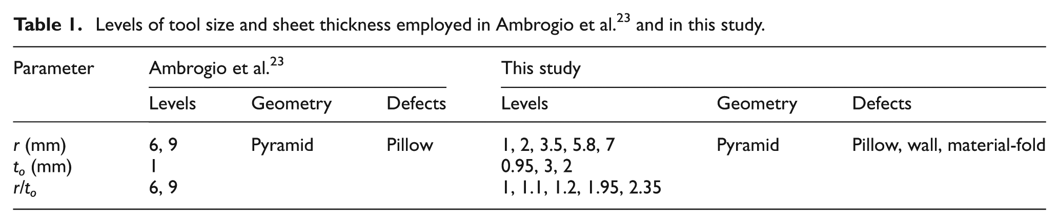
Results of tests conducted with tools comparatively smaller than those employed in Ambrogio et al. 23
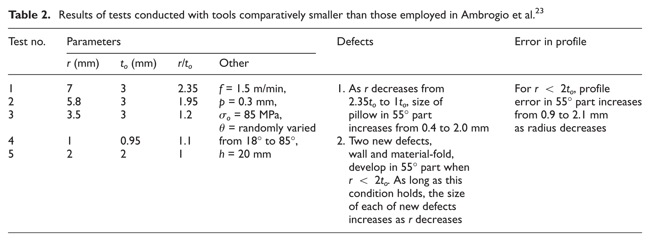
As shown in Table 2, the size of pillow defect (i.e. pillow height from the center of part’s bottom, Figure 2) in 55° pyramid increases from 0.4 to 2.0 mm as the tool radius with respect to sheet thickness (i.e. r/to) decreases from 2.35 to 1.0. The said effect, however, has been found to be more intensive for r<2to than for r>2to. Due to this reason, for r<2to, overall error in the profile of 55° pyramid increases (1.95–1 mm) as the tool radius decreases (1.95–1 mm). This finding is contrary to Ambrogio et al. 23 according to which overall profile error decreases with decreasing tool size. Furthermore, it clarifies that in order to improve profile accuracy, pillow needs to be controlled for which tool size should be opted with respect to the thickness of sheet.
Schematic representation of pillow defect and its effect on part profile.
In addition to pillow, two more defects were observed during tests. These defects can be termed as wall and material-fold, as mentioned in Table 2. The wall develops in the tool/sheet contact zone, and the fold develops on the outer surface of corner of pyramid as schematized in Figure 3(a) and evidenced in Figure 3(b). Both of these defects, as stated in Table 2, develop when the tool radius with respect to sheet thickness is inappropriately low (e.g. r<2to as found for 55° pyramid). Due to unduly low size, the tool in fact loses its ability to thoroughly depress the sheet and consequently penetrates into sheet material during its downward motion (i.e. in z direction). As this penetrated tool performs feed motion (i.e. along x- and y-axes), the material from the tool/sheet interface squeezes out which in succeeding forming loops heaps and thus makes a wall. The depressing capacity of small tool further reduces as it approaches the corner of pyramid. Because, according to Hussain et al. 24 and as indicated in Figure 3(a), the tool encounters comparatively larger material stiffness while making a corner than making remainder geometry. As a result, the material at corner site is not completely deformed through its thickness. The material on the outer surface of corner most probably remains elastic and therefore, in an attempt to attain its original state, folds backward after the tool has passed by the corner site. It is to be noted down that the wall and material-fold develop under the same tool-size condition, and furthermore, these defects simultaneously occur in the pyramid geometry. However, the pillow does not necessarily follow this condition. For an example, for the set of conditions shown in Table 2, wall and fold defects develop in 55° pyramid only when r<2to, but pillow forms even with larger radii, that is, r>2to.
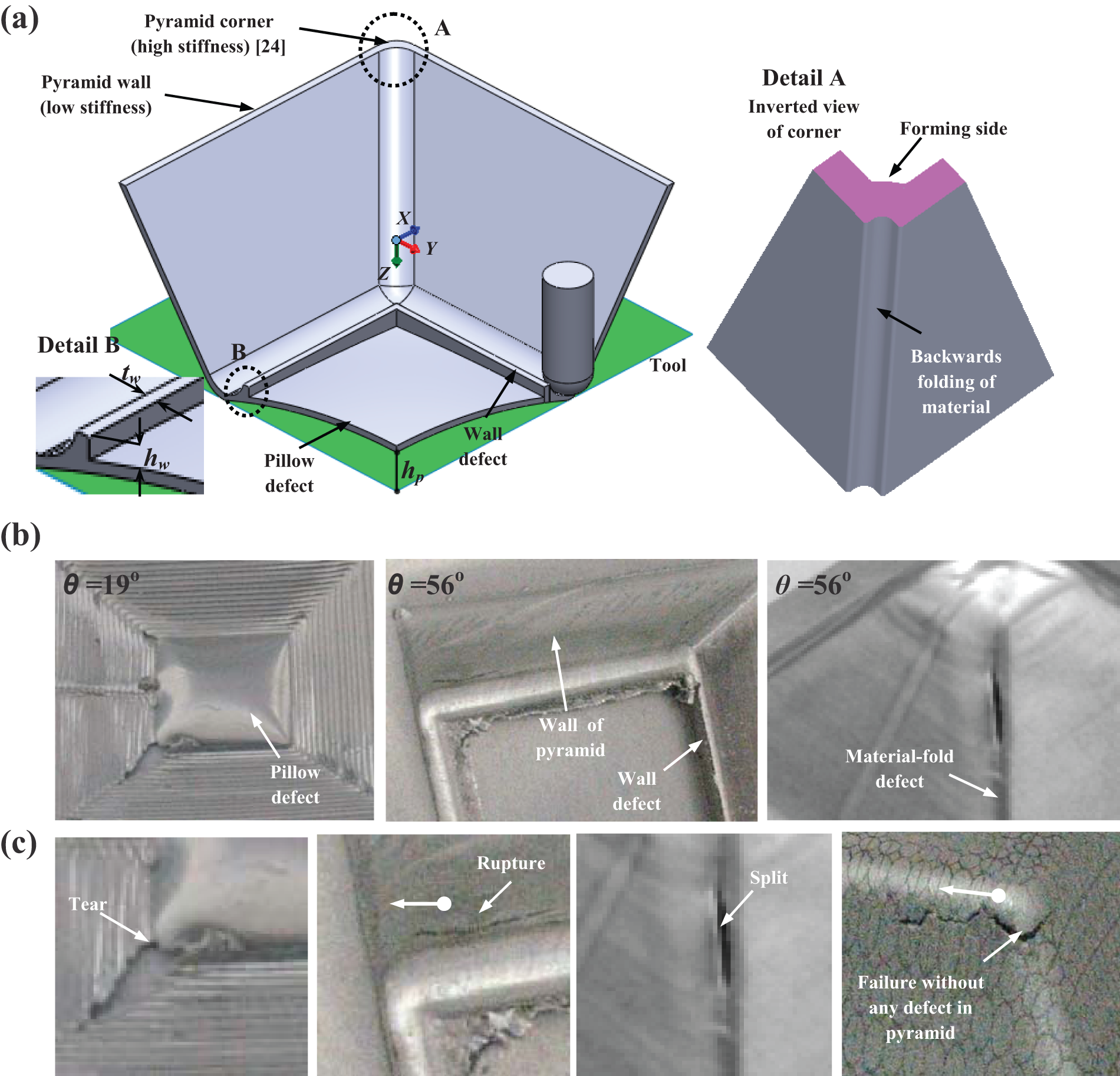
Defects in SPIF process: (a) schematic representation and terminology of defects, (b) evidence of defects in pyramid and (c) fractured surfaces showing various failure modes as a result of defects.
Figure 3(c) exhibits various surfaces, which fractured, due to the development of defects, while forming pyramids with various wall angles (say 19° and 56°). For the sake of comparison, a surface fractured without any effect of defects is also shown. Based on the examination of these surfaces, three failure modes as a result of defects can be identified in sheet. These may be termed as tearing, rupturing and splitting. As can be seen from the photograph, each failure mode is a characteristic of specific defect. Tearing, which is sudden breaking of material at the interface of wall-end and the bottom of pyramid, occurs due to the development of overly large pillow in the bottom. Rupturing, a hairline crack that after initiating in the wall of pyramid propagates toward the corner as indicated by an arrow in the photograph, incepts as a result of growth of wall defect in the tool/sheet contact. Splitting, which is separation of corner into two segments along its length, takes place because of the folding of material at corner. All the said failure modes represent ductile fracture because the sheet material before fracturing undergoes deformation. Furthermore, the way of fracturing in each of these failure modes is different from the one observed in the normal sheet failure (i.e. in the pyramid having no defect, a crack initiates at the corner and propagates toward the wall of pyramid). This is to be seen from the pyramids having defects (Figure 3(b)), the sheet failure due to a specific defect does not occur in the beginning of forming; instead, it takes place after the defect (or part) has grown to a certain height. For an instance, material tearing in 19° pyramid occurs when the pillow height becomes 3 mm, which is achieved after the pyramid has attained 11 mm height. This result indicates that the stress level in a part increases as the defect size increases, and fracture due to a defect occurs when the stress reaches a certain level.
Figure 4 depicts the formability of 3-mm-thick sheet, which was determined with as well as without having defects in the test specimen (i.e. processed with tool radii of 1.2to and 3to, respectively). As can be seen, the formability of sheet reduces by 25% due to pillow and by 34% due to each of the wall and fold defects. This finding reveals that the development of defects does not pose adverse effect only on the part accuracy, discussed before, but also badly affects the formability of material.
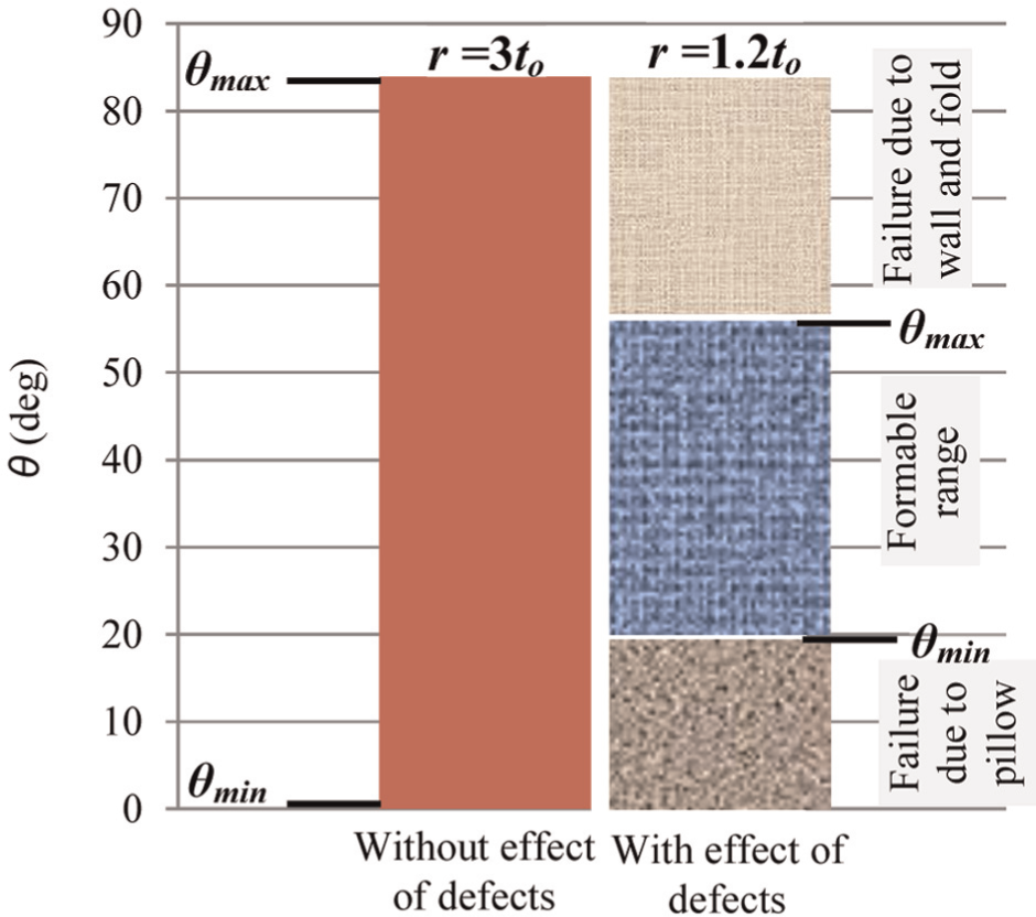
Effect of defects on the formability of 3-mm-thick AA1060 aluminum sheet.
As evidenced in Figure 3 and indicated in Figure 4, the tear failure occurs in low-angle parts (1°–19°) and failure due to rupture or (and) split occurs in high-angle parts (56°–84°). This means pillow affects the lower limit of wall angle, and the remaining two defects influence the upper limit of wall angle to which a part can be successfully formed without fracturing. The range of wall angle between these two limits (20°–55° as pointed out in Figure 4) can be termed as safe range because parts within this range, even with the development of defects, can be formed to certain required depth without failure. As an instance, pyramid with 20 mm depth and r = 1.2to (i.e. with defects) was observed to be successfully formed within safe range, but the same could not be formed beyond this range. Based on these findings, it can be said that the formability in SPIF is limited not only by a maximum value of wall angle without sheet fracture (θmax); rather there is a minimum wall angle (θmin) as well below which sheet failure occurs if a part while forming suffers from a severe defect (or defects). Thus, the formability in SPIF, contrary to the conventional measure θmax, 18 needs to be defined as a range from θmin to θmax. This formability range, however, can be extended to θmax by increasing the tool radius, as demonstrated in Figure 4.
In order to clarify whether a change in geometry has effect on the nature of defects, three tests (no. 2, 3 and 4) in Table 2 were repeated by replacing pyramid with cone. In Tests 3 and 4, two defects, namely, pillow and wall, were observed as evidenced in Figure 5. However, folding of material (i.e. material-fold) did not occur in either of the tests. These are the same tests in which defects, including material-fold, were observed in pyramid. This means the conditions under which defects develop are same for both the cone and pyramid geometries. However, the cone geometry that is a round shape does not suffer from fold defect, which indicates that this particular defect is a characteristic of corner in a shape. Therefore, it can be concluded that material folding occurs only in geometries having corners.
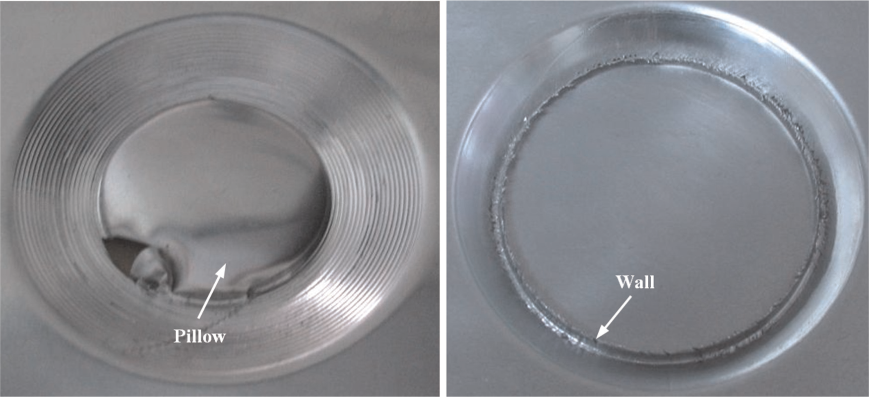
Defects in cone geometry.
The above discussed results provide in-depth understanding of material behavior in SPIF with unduly small tools. It is found that inappropriately small tool, besides accelerating growth of pillow, induces additional defects in a part. Furthermore, the size of these defects and their adverse effect on process performance (i.e. profile error and formability) reduce as the tool size is increased. This means there is a certain limit on choosing minimum size of tool following which the development of defects can be overcome. To accurately determine and to elucidate whether there is any effect of variation in process parameters on the said limit, further investigations were conducted as detailed in the next section.
Investigations on the effect of process parameters on defects’ growth and on tool size for individual control of defects
As proposed earlier, the above found defects can be overcome if the low limit of tool size is defined. This limit due to change in the size of defects, if any, may vary as a process parameter is varied. In order to clarify this point, the effect of five process parameters, namely, sheet thickness (to), step size (p), feed rate (f), yield strength (σo), and wall angle (θ), on the defects was systematically investigated as shown in Table 3. Each parameter was varied over two levels. The required levels for yield strength were obtained through work-hardening of AA1060 aluminum material. (Due to pre-straining, on one hand, the yield strength of material increased from 40 to 110 MPa, but on the other hand, the strain rate exponent decreased from 0.2 to 0.04.) Initially, the effect of each parameter on the size of each defect was quantified by using a fixed tool, small enough (i.e. 3 mm radius) to instigate defects in the pyramid specimen. Later, to control each particular defect in every test listed in Table 3, the tool radius (starting from 3 mm) was increased in small steps until the defect had been overcome. The minimum value of tool radius which overcame a specific defect was termed as the least-radius limit for that defect.
Effect of variation in some process parameters on the size of defects and on the least-radius limit of each individual defect.
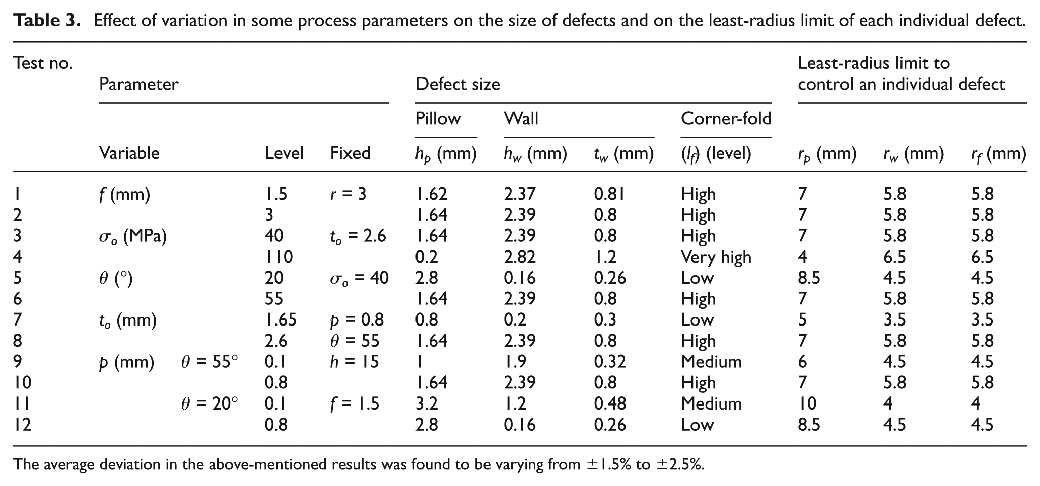
The average deviation in the above-mentioned results was found to be varying from ±1.5% to ±2.5%.
In order to quantify the effect of variation in the above-mentioned five parameters, the size of each defect was defined as shown in Figure 3(a) and given as follows: (1) pillow: maximum height of pillow from the part center (hp); (2) wall: thickness (tw) and height (hw) of cross section of wall; and (3) material-fold: since fold is difficult to measure, its size was defined as level (lf) varying from nil to very high. The necessary defect measurements were made with vernier caliper having 0.01 mm resolution.
Table 3 presents the effect of investigated parameters on the size (or growth) of defects. As expected, most of the investigated parameters are influential. The feed rate, however, does not pose any significant influence on the growth of defects (Tests 1 and 2). This means forming can be executed with high feed rate, and thus, manufacturing time can be significantly reduced at no cost to product quality in terms of defects.
As can be seen from Table 3, the effect of yield strength (Tests 3 and 4) and wall angle (Tests 5 and 6) is very interesting. On one hand, an increase in these two parameters impedes the growth of pillow (hp), but on the other hand, the same accelerates the growth of wall and fold defects (i.e. the size hw, tw and lf increase). This implies that sheet failure due to tearing (a failure mode associated with pillow defect) is more likely to occur in a part having low wall angle (e.g. 56°) and low yield strength (e.g. 40 MPa) than in a part having high values of these parameters (e.g. 56° and 110 MPa). Conversely, sheet failure due to rupturing or splitting (failure modes related to wall and fold defects, respectively) is more probable to occur in a part being processed with high values of wall angle and material strength than in a part being processed using low values of these parameters. This finding explains why pillow defect limits the formability of low-angle parts and why the other two defects reduces the formability of high-angle parts, a result discussed in the preceding section and evidenced in Figure 4.
With increase in sheet thickness, there is increase in the size of all defects (Tests 7 and 8, Table 3). However, the effect of step size depends on the wall angle employed. With a high wall angle (e.g. 55°), growth of all defects (Tests 9 and 10) accelerates as step size increases. But at a low wall angle (e.g. 20°), the same retards as step size is increased (Tests 11 and 12).
In order to control the development of each individual defect, the necessary tool size for every test has been proposed in Table 3. For an example, to control wall in Test 2, a minimum radius of 5.8 mm has been recommended. This proposed size of tool, denoted as rw, in fact defines a low limit on choosing tool radius. Thus, rw in Test 2 means that a tool with radius less than 5.8 mm may not be opted in order to preclude wall defect. This certain radius limit can be termed as the least-radius limit for wall. Similarly, least-radius limit for material-fold and pillow defects can be defined as rf and rp, respectively. As anticipated, the least-radius limit for each particular defect varies as a process parameter, except feed rate, is varied (Table 3). Also, each radius limit follows its corresponding defect in responding to variation in a parameter. For an instance, the size of pillow increases as sheet thickness increases, the radius limit rp accordingly exhibits the same trend. This is to be noticed from Table 3 that in each test rw = rf. This means for a given set of conditions, both the wall and fold defects can be overcome by employing one tool. In most of the tests, except in Test 8, whereby material strength was raised by pre-straining, rp>rw, rf, which indicates that controlling pillow in soft metals is more demanding than controlling wall and fold.
Investigation on simultaneous control of all defects
Even if the development of a defect (or defects) does not cause part failure, as found in safe range shown for certain conditions in Figure 4, it needs to be overcome for the sake of quality (accuracy and esthetics) of components. As found earlier and evidenced in Table 3, the least tool radius in each test required to control pillow is different from the one needed to overcome other defects. But for the aforesaid purpose and to reduce efforts, there must be only one tool size that would simultaneously control all defects. As an example, rp (7 mm) in Test 2 being the largest least-radius among all radius limits (rp, rw, rf) can easily overcome wall and fold in addition to pillow. This radius limit, which simultaneously controls all defects for a given set of conditions, can be denoted as rl. Although, relation between the radius limit rl and process parameters is somehow understandable from Table 3, the interactive effect of parameters on rl is not adequately clear. In order to thoroughly understand the said effect, if any, a DoE was conducted.
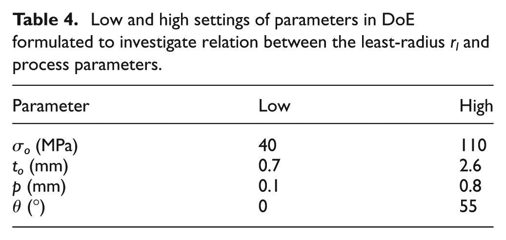
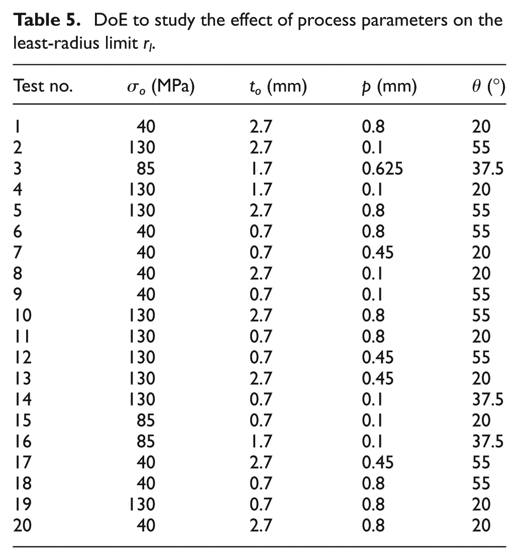
As found before, feed rate (f) does not pose any significant effect on defects growth. Therefore, this parameter was dropped from the list of five parameters considered in the previous section, and investigations to determine the possible interactive effect of parameters on the least-radius limit rl were conducted with remaining four parameters. These include yield strength (σo), sheet thickness (to), step size (p) and wall angle (θ). In order to formulate a comprehensive test plan, a commercial statistical package (Design-Expert Dx7) was used. 25 This package offers several methods, each of which is based on principles of statistics, to design experiment plan. For the current analysis, D-optimal design (a response surface (RS) method that presents results in a form of three-dimensional (3D) surface) was opted because this method, compared with others, requires less number of experiments without compromising on result accuracy. 26 The low and high settings of aforesaid four parameters, as shown in Table 4, were fed into Dx7 package. The software in turn, after ensuring its correctness, prepared a test plan of 20 runs as listed in Table 5. All the tests were performed with fixed depth (15 mm) and using the same material (AA1060) and geometry (pyramid) as employed for the tests in section “Material behavior in SPIF with very small tools.”
Low and high settings of parameters in DoE formulated to investigate relation between the least-radius rl and process parameters.
DoE to study the effect of process parameters on the least-radius limit rl.
Analysis of variance: significance of tested parameters and interactive effects
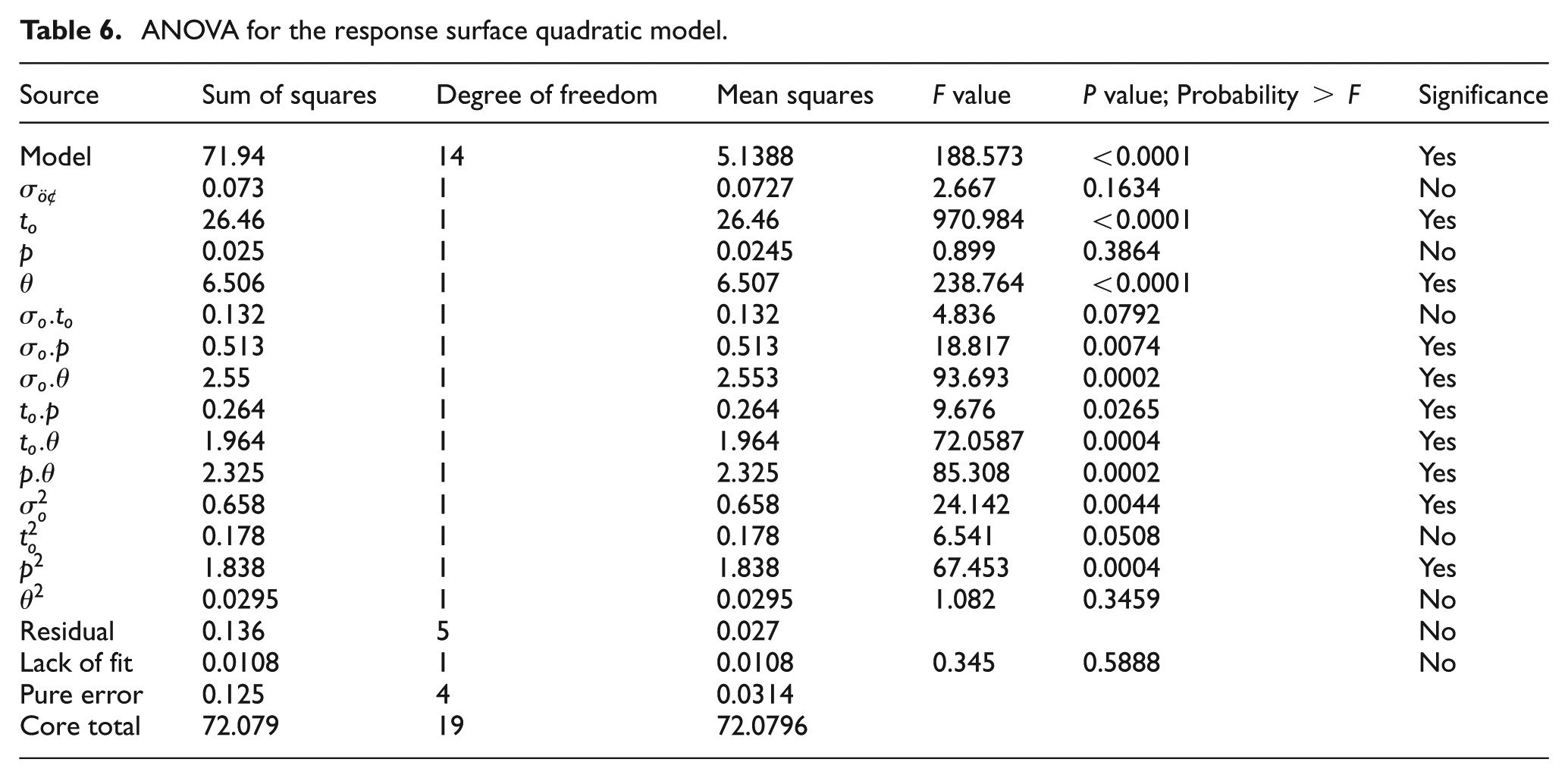
To know the significance of a tested parameter for a response (i.e. rl in this case), analysis of variance (ANOVA) is an essential test to be performed. To do so, response against each of 20 runs was fed into Dx7 software, and a mathematical model (i.e. quadratic for the present case) that best fits the datum points of design space was opted.
Table 6 lists the results of ANOVA test. As expected, the investigated parameters are involved in interactions. This means the role of parameters on individual basis is not so meaningful. Also, the interacting parameter (or parameters) is necessary to be considered in order to properly understand the effect of each specific parameter on the least-radius limit
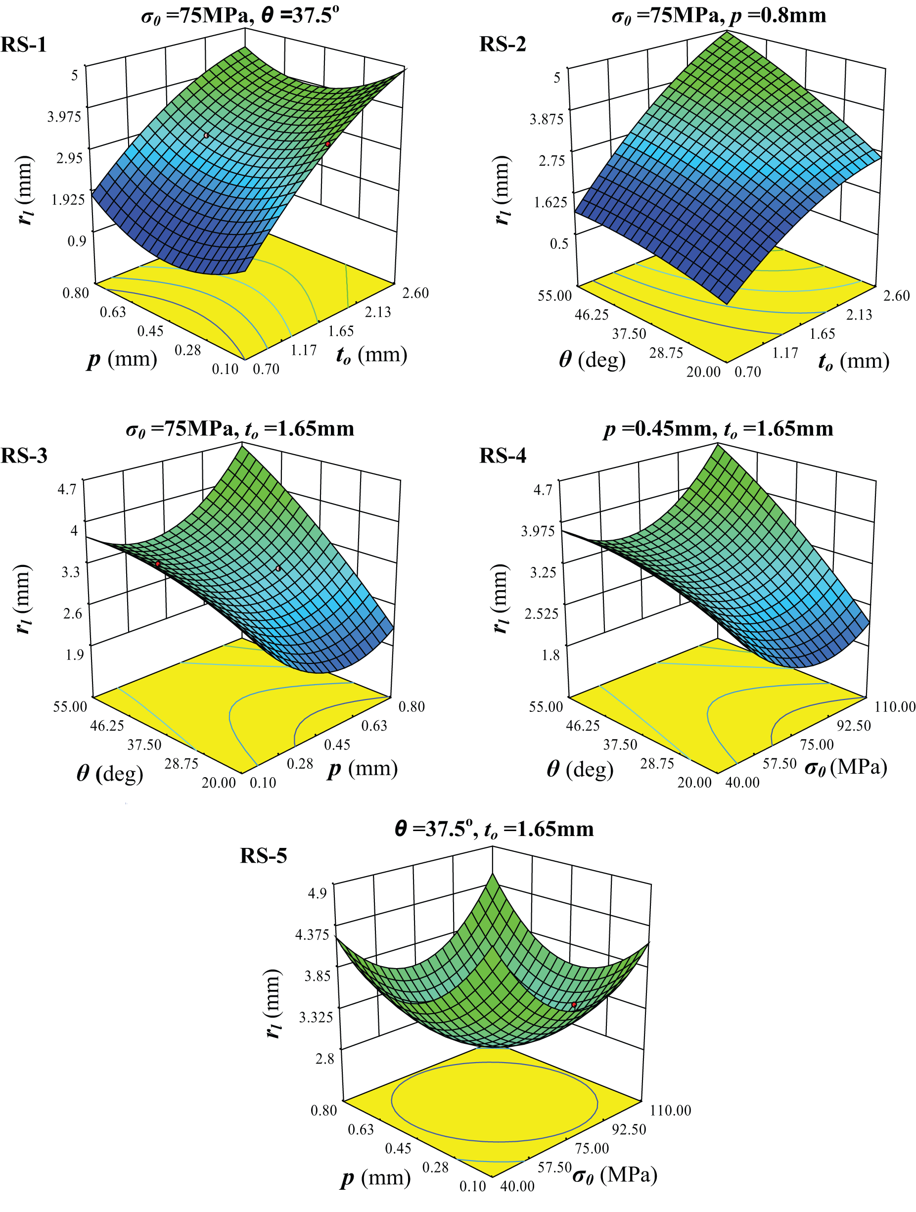
The combination of low step size (0.1 mm) and high thickness (2.6 mm) requires a larger tool (i.e.
The combination of low wall angle (20°) and high thickness (2.6 mm) needs a bigger tool than the one of high wall angle (55°) and low thickness (0.7 mm) (RS-2).
The combination of low step size (0.1 mm) and high wall angle (55°) calls for higher tool size than the one of high step size (0.8 mm) and low wall angle (20°) (RS-3).
The combination of low yield strength (40 MPa) and high wall angle (55°) demands a larger tool than the one of high yield strength (110 MPa) and low wall angle (20°) (RS-4).
Intermediate value of yield strength (75 MPa) and step size (0.45 mm) call for a comparatively smaller tool (RS-1, 3, 4, 5) than their extreme values (i.e. 0.1 or 0.8 mm).
ANOVA for the response surface quadratic model.
Effect of significant two-factor interactions on the least-radius limit rl
According to the above-mentioned findings, the least-radius limit rl varies with a variation in the considered parameters. Furthermore, the said effect of parametric variations is highly interactive in nature. This in fact is an outcome of the interactive effects of parameters on the defects, which were discussed in the preceding section and have been shown in Table 3. Due to these interactive effects, as is dictated by the analysis of RSs, both the low and high values of step size and yield strength are not appropriate to simultaneously control all defects. Therefore, it is more judicious to employ an intermediate step size (i.e. p = 0.45 mm) and raise the material strength to an intermediate level (i.e. σo = 75 MPa for AA1060 material). The reader may note down that the material strength can be raised by work-hardening, as was done in this work.
Empirical formula
Though one can know the least-radius limit rl using the RSs shown in Figure 6, these surfaces are valid only for the forming conditions shown in the surfaces. In order to determine rl for any required combination of parameters, but within the investigated limits, the following hyper surface (a mathematical model) is proposed
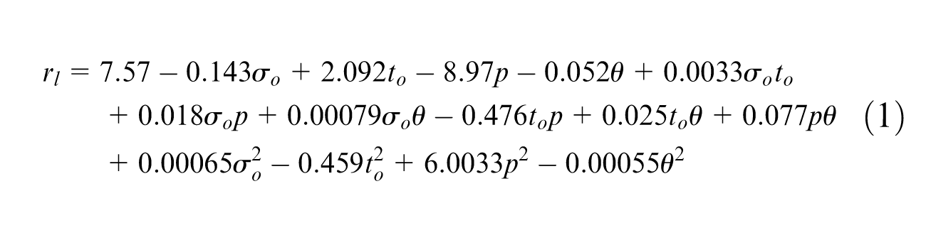
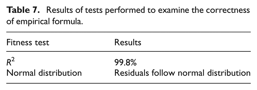
In order to examine the correctness of above-mentioned empirical model, two tests (R2 and normal distribution of residuals) were performed using Dx7 software. The results of these tests have been listed in Table 7. It can be seen that R2 (multiple correlation factor) has a very high value (99.8%), which means that the datum points are well fitted to the curve of model. Moreover, the internally studentized residuals fairly follow a normal distribution (see evidence in Figure 7). Both these tests dictate that the proposed model fulfills the fitness criteria as detailed in Anderson and Whitcomb; 26 therefore, it can be said that the model is correct.
Results of tests performed to examine the correctness of empirical formula.
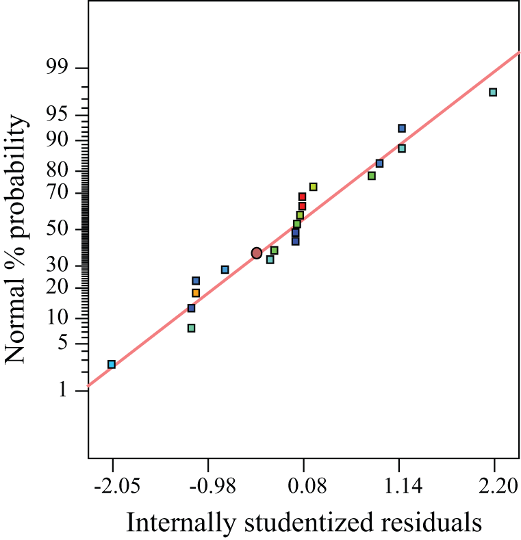
Normal plot of residuals.
The applicability of above-mentioned empirical formula to a geometrical shape other than pyramid (i.e. experimental) was also examined. To do so, cone with the same size as employed earlier for pyramid was opted. The following conditions were chosen to perform the test: σo = 110 MPa, to = 1.4 mm, p = 0.4 mm, θ = 55° and h = 20 mm. The above-mentioned formula against these conditions proposed an rl value of 4 mm. While performing test with the proposed radius, no significant development of defects was observed. Afterward, an additional test by varying cone depth from 20 to 70 mm was carried out. The part once again successfully formed without any fracture. These findings confirm that the empirical formula, which was initially proposed for pyramid, is applicable to other shapes (especially cone) as well. Also, it further verifies the correctness of proposed model. Therefore, it can be concluded that the model, within the investigated range of parameters, can be reliably used for predicting least-radius limit rl to concurrently control all defects.
Conclusion
This study was undertaken with an objective to rectify the previous omission 23 and to clarify the role of tool size in causing and controlling development of defects in the SPIF process. The important findings of this study are summarized below:
The pillowing of sheet material in a part’s bottom generally increases as the tool radius decreases. However, the growth (or size) of pillow in a certain range (e.g. r<2to as found for the conditions employed in section “Material behavior in SPIF with very small tools”) becomes increasingly intensive with decreasing tool radius. As a result, discrepancy between the experimental and designed profiles of part increases accordingly. This means employment of a small tool, contrary to Ambrogio et al., 23 does not necessarily improve geometrical accuracy; rather to control accuracy tool size should be opted according to the sheet thickness.
The choice of an unduly small tool (e.g. r<2to for 0.3 mm step size and 40 MPa yield strength), while forming, results in the development of two more defects besides a large pillow. These defects have been termed as wall and material-fold. The wall is an outgrowth of material squeezing from the tool/sheet interface, and the material-fold is a consequence of folding of partially deformed material on the outer surface of the corner of a part. The fold defect is a characteristic of the geometry having corners (e.g. pyramid). However, the remaining two defects can develop in any part irrespective of the geometrical shape.
The development of a defect can cause premature sheet failure during forming. Excessive pillowing can cause material tearing in the bottom of part. The squeezed-out wall may result in sheet rupturing. The material-fold may split a part’s corner into two segments. As a consequence of either of these failure modes, if occurs, sheet formability reduces.
The sheet failure due to pillowing is more likely to occur in a low-angle part (e.g. 20°) because pillow growth is higher in a low-angle part than in a high-angle part (e.g. 55°). Conversely, sheet failure due to wall or (and) fold defect is more probable to occur in a high-angle part because the growth of these defects accelerates as wall angle increases. This means the formability in SPIF, if defects develop, is reduced to a range between the maximum and minimum wall angles without sheet fracturing (i.e. θmax–θmin). Therefore, the formability in SPIF needs to be defined as a range from θmin to θmax instead of θmax (a conventional formability measure in SPIF).
All the defects in SPIF, discussed in this study, can be simultaneously controlled if the tool with radius less than a certain limit is not opted. This limit is termed as the least-radius limit (rl). It varies as a process parameter (except feed rate) considered herein varies. Furthermore, the effect of parametric variation on rl is highly interactive. Due to this reason, it is proposed, as dictated by RS analysis, to perform the SPIF process with intermediary values of step size (e.g. 0.45 mm) and by raising the material yield strength (e.g. 75 MPa for AA1060) to intermediate level.
An empirical model to predict
Future work
The FE analysis in order to understand the scientific facts behind the reported findings is underway and will be submitted later.
Footnotes
Appendix 1
Acknowledgements
The author is thankful to Prof. Dr Ugur Atikol and Mr Hosein Khalatbari for providing technical support to accomplish the reported work.
Declaration of conflicting interests
The author declares that there is no conflict of interest.
Funding
This research received no specific grant from any funding agency in the public, commercial or not-for-profit sectors.