
Abstract
A new forming method, three-dimensional flexible rolling, is proposed for three-dimensional surface parts, which can form the parts effectively with the dieless characteristics. In this study, the shape of bending rolls is circle and the bending radii of upper and lower rolls are different; therefore, the roll gap is non-uniform. Because of the roll gap, an uneven compression appears at the transversal direction, which leads to a non-uniform elongation in feeding direction. The parts bend in two directions at the same time, and the three-dimensional surface shape is obtained. The forming rules of flexible rolling are proposed to analyze the relationship between the pressure ratio and the deformation extent of double-curved surface. The function between the non-uniform roll gap and the bending radius is deduced from the theory of invariable volume. An experimental device is developed to do the forming experiments. The feasibility of the device and the advantage of the method have been validated through numbers of experiments. Typical three-dimensional surface parts such as the convex and saddle parts have been completed for researching and analyzing. Some fine numerical simulation results of flexible rolling have been obtained. Finally, the simulation results are compared with the actual results to analyze the shape and illustrate the forming effect.
Keywords
Introduction
Flexible rolling is a rolling technology, which has greater flexibility and adaptability in the rolling process. Liu et al. 1 put forward the flexible rolling technology in traditional rolling process. The method of online optimizing control is applied in flexible rolling, which is producing parts with different properties from the blank with the same ingredient. Krux et al. 2 controlled the roll gap in real-time to obtain the thickness shape of two-dimensional (2D) plates in the rolling direction by flexible rolling technology. The 2D formed parts can be obtained by using flexible rolling in the traditional rolling. However, the formed parts are realized by bending in one direction; they belong to the scope of the 2D continuous rolling.3–5
With the three-dimensional (3D) continuous forming as a new way for sheet metal forming, it can manufacture 3D surface parts rapidly and efficiently. Yamashita and Yamakawa 6 and Yoon7–10 attempted to study the method, but the forming results are not ideal. Li11–18 researched the continuous flexible forming method for 3D surface parts based on the idea of flexible roll forming and obtained favorable results. On this basis, Li et al.19–23 put forward the flexible rolling method for the forming of 3D surface parts. The method combines multi-point adjusting and traditional rolling technology. The forming mechanism of 3D surface parts has been set forth, and the theory of surface controlling and the effects of forming parameters have been studied in the forming process. The forming device of the flexible rolling has been developed. Plenty of experiments have been done and some fine experimental results have been obtained including convex and saddle surface parts. 24
Based on the previous work, this study analyzes the thickness thinning situation according to the transversal bending radius, deduces the longitudinal bending radius by the algorithm of transcendental equations, gives the relationship between the pressure ratio and the deformation extent of double-curved surface and compares the forming effects between the theoretical and simulation results in transversal and longitudinal directions.
Flexible rolling forming principle
The equipment of flexible rolling developed by Dieless Forming Technology Center in Jilin University is shown in Figure 1(a). Specific geometric parameters of the device and rolling workpieces are as follows: the diameter of flexible working rollers is 10 mm, the range of workspace is 1200 mm and the length of adjusting element is 40 mm. Regulated and supported by adjusting mechanism, the forming rolls rotate and cause the sheet metal to be deformed continuously in the forming process. The distribution of the roll gap is uneven as shown in Figure 1(b). The diameter of the forming rolls should be small and the material should be hard because the rolls should be able to rotate around their bending axis with a small-scale bending. Therefore, the work roll bending is difficult if a larger diameter is selected. However, if we select a smaller diameter, it will be easily broken with the work roll rotational speed. This forming method is still in the experimental stage, and the selection method of flexible rolls is a feasible solution based on many experiments. For the comparison of the different roll diameters to complete the forming, it will be analyzed in the future.
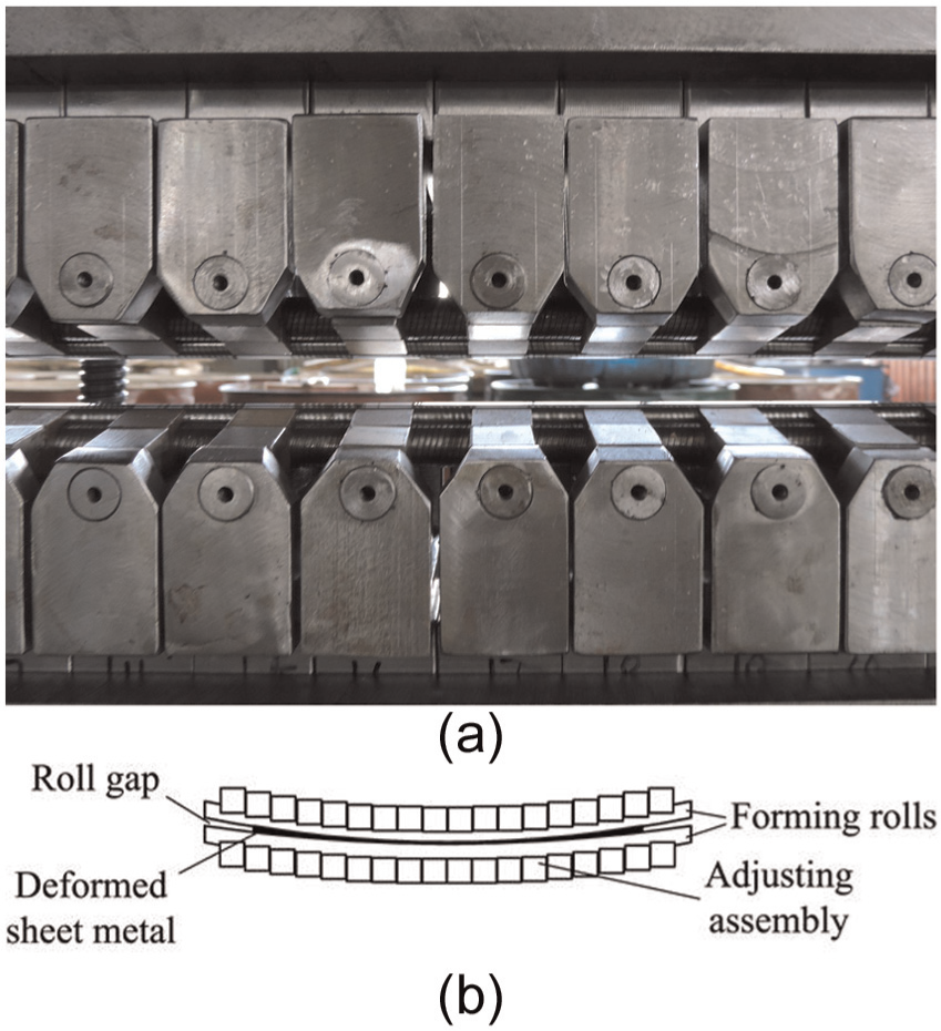
Experimental device: (a) apparatus photograph and (b) controlling of the shapes and the roll gap.
Bending deformation of the sheet metal in the transversal direction is caused by the bended rolls. Uneven plastic strain occurs in the longitudinal direction, which causes the different thinning point by point in the transversal section. The thickness of the sheet metal after being formed is consistent with the height of the roll gap. Since the plastic deformation in the forming process is large, and the flakiness ratio is very small, the extension in the width direction can be ignored. The transversal shape of the formed parts depends on the adjusted profile of the forming rolls and can be analyzed through the cross section of the roll gap.
Meanwhile, the thinning leads to the non-uniform elongation in the feeding direction and then the subsidiary stress appears. The non-uniform compression causes uneven longitudinal elongation. The elongations are different line by line in the longitudinal direction. Therefore, subsidiary stress appears. The sheet metal produces a longitudinal bending because the elongations are restricted by the stress. The whole longitudinal bending deformation is accomplished under the action of tension. With combined action of two directions’ bending deformations, double-curved surface parts are formed continuously by the rotation of the forming rolls.
Algorithm design for flexible rolling
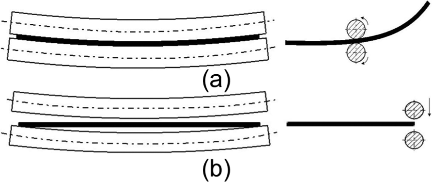
If the bending radius of the upper and lower forming rolls is equal, the roll gap is uniformly distributed and the thinning of sheet metal is uniform, which can form 2D curves. Convex curved parts will be formed when the bending radius of the upper rolls is smaller than the lower, if not the saddle parts will be formed. As described above, the shape of the surface parts is decided by the roll gap and the configuration shape of the forming rolls. But the units of adjusting assembly are too many to control and the relationship of the rolls is needed to deduce. Algorithms are designed to obtain radius, thickness, bending rule and so on conveniently for the analysis of formed parts. The algorithms in this chapter are given to obtain the shape of convex and saddle surface parts, which will be applied in the industrial processes widely. The gap function is an even function, which is symmetric about the center line of the gap. In the forming process for convex surface parts of flexible rolling, the pressure ratio in the middle is maximum on the transversal cross section, while zero at the edges. With the upper roll pressing down, the thinning area crosses the width of the sheet metal, but the biggest value is in the middle as shown in Figure 2(a). Longitudinal elongation is produced in accordance with the thinning area and eventually convex surface part is formed. The other situation for the saddle parts, the pressure ratio of the edges, is maximum on the transversal cross section and zero in the middle. With the upper roll pressing down, the thinning area crosses the width of the sheet metal, but the biggest value is on both sides as shown in Figure 2(b). Longitudinal elongation of the edges is bigger than that in the middle, and the saddle part is formed eventually.
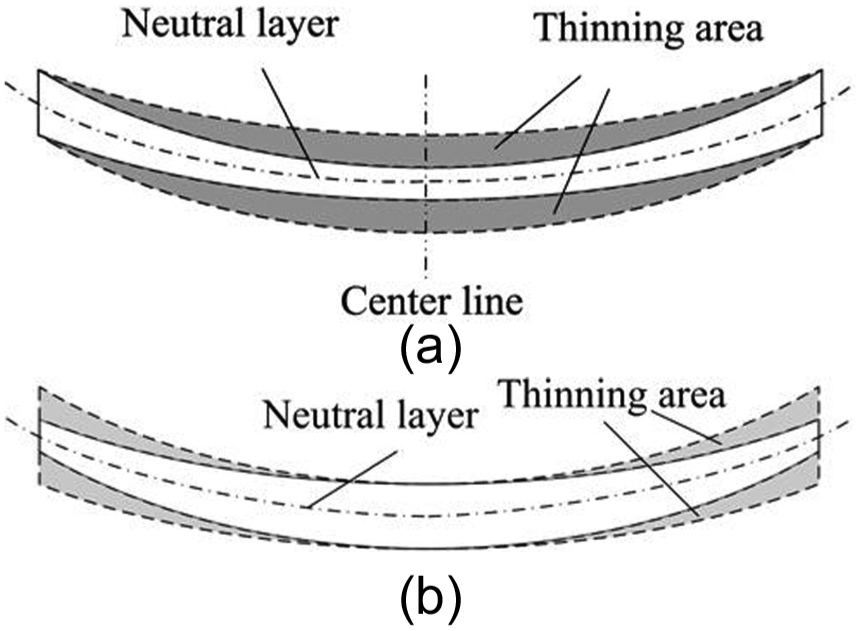
Schematic of flexible rolling: (a) convex parts and cross section and (b) saddle parts and cross section.
Transversal direction algorithm
The shape of the transversal section is composed by the roll profiles. The forming rolls are closed to the surfaces of sheet metal to form continuously. The transversal function of the surface can be approximately equivalent to that of the rolls. The upper forming roll presses with the pressure ratio, and the first procedure of flexible rolling is completed. The variation in the roll gap is reflected mainly by the pressure ratio. The functions of the roll shapes and roll gap are main design for flexible rolling because they are significant references for the shape and thickness of the formed parts.
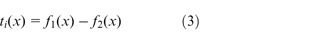
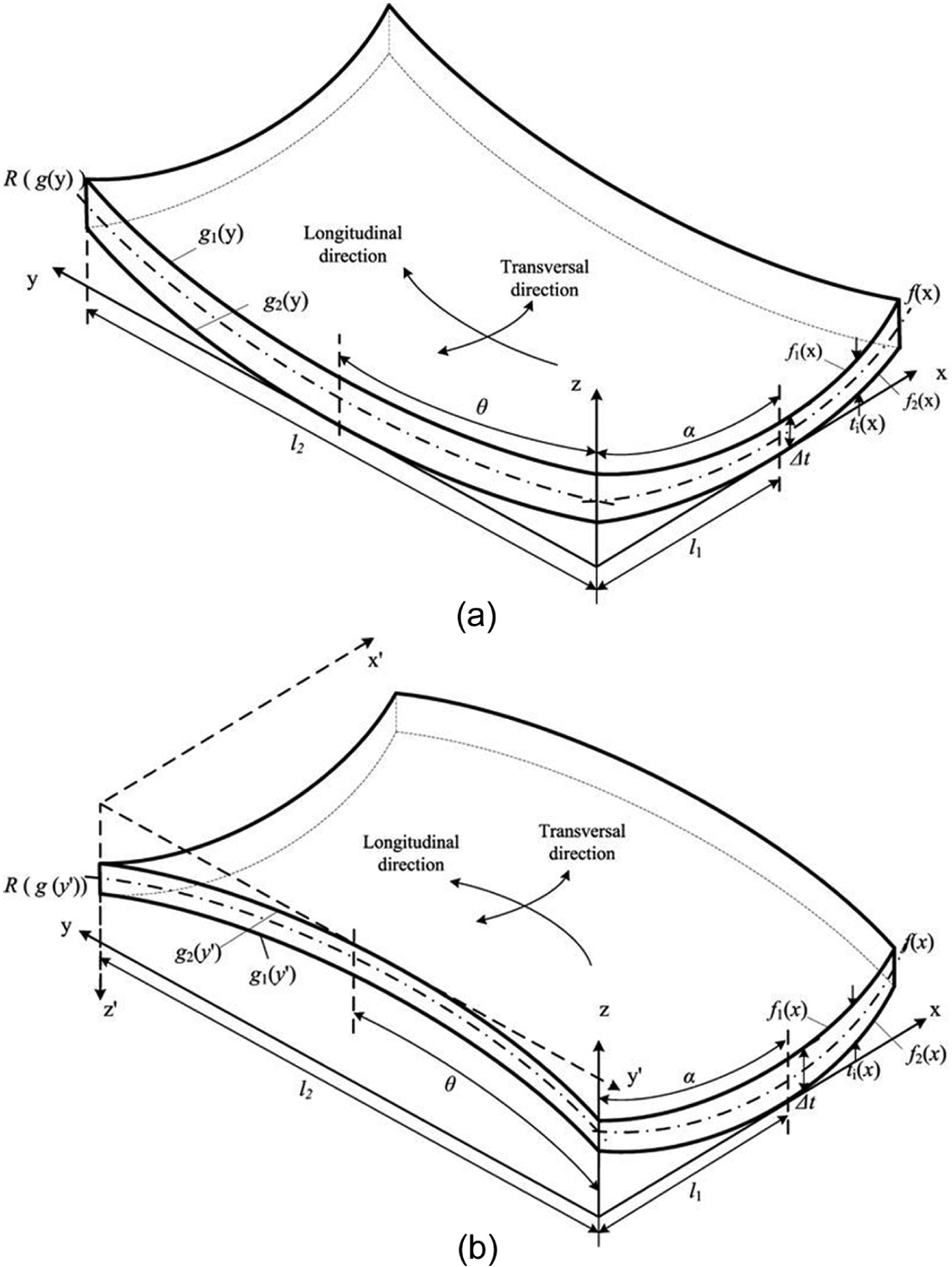
The shapes of the roll gap and work roll profiles remain unchanged during the forming process. As shown in Figure 2, the neutral layer of formed parts is consistent with the middle curve of the roll gap. Roll shape function is considered to be consistent with that of transversal section approximately. As presented in Figure 3, the neutral layer equation is established in equations (1) and (2)
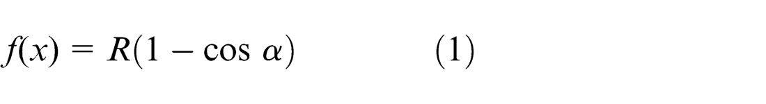
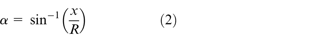
where R is the target transversal radius of the formed parts. Roll gap function is related to the thickness. When the thickness is very small but the wide is relative large, according to the law of least resistance, the sheet metal flows along the width direction very few, namely, the width expansion of the formed parts can be ignored. When the pressure ratio is decided, according to the theory of invariable volume, thickness can be worked out
Analysis of formed parts: (a) convex profile and (b) saddle profile.
Combined with the neutral layer equation, roll shape function can be obtained by the following equations
where
The change in the formed surface has much to do with that of the forming rolls. It can be explained by comparing the transverse curvatures of the neutral layer and the changes in thickness when to analyze the shape in the transversal direction.
Feeding direction algorithm
Theoretically, when the pressure ratio is decided,
When the pressure ratio is decided, according to the theory of invariable volume, the related algorithm is
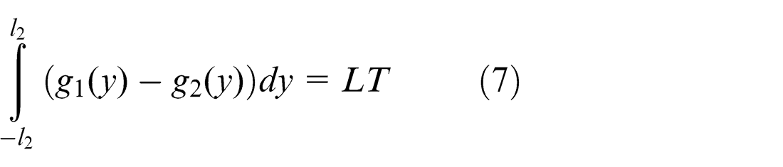
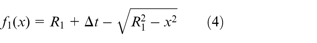
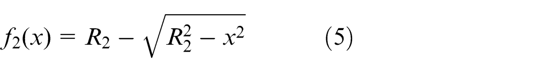
where L is the length of the sheet metal and T is the original thickness. As shown in Figure 3(a), the functions of the upper and lower surface are
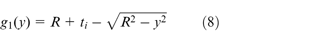
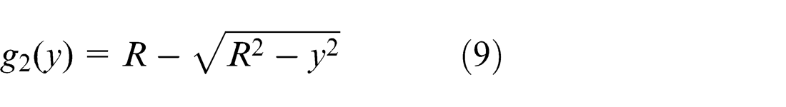
So, equation (7) can be simplified as
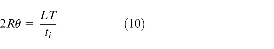
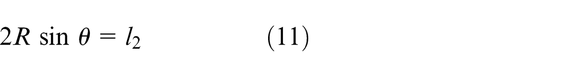
The arc length l 2 can be decided by equation (10). The relationship of the trigonometric function is obtained
Equations (10) and (11) are converted to equivalent equations in order to be solved easily
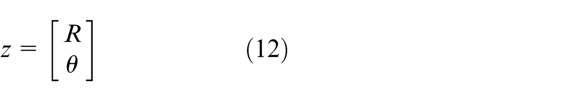
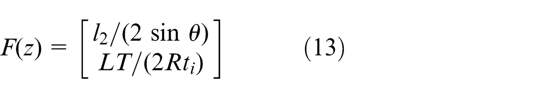
When the arc length is decided, the radius has a unique solution. The equations composed of equations (12) and (13) have identified a unique solution, which satisfies the convergence condition of nonlinear equations. Within the range threshold, the appropriate initial vector (
Forming experiment and simulation
In this study, the experimental parts and the simulation results are applied as the research objects. The application of flexible rolls can realize the bending curvature change in the forming tools. The shape of the forming rolls is adjusted by adjustment mechanism specialized in the forming process. After the end of adjustment, thickness can be obtained by moving down the upper forming roll according to the reduction. The change in transverse curvature obtained is shown in Figure 4(a). The main work is to control the reduction ratio and adjust the shape of the rolls. With the non-uniform elongation in feeding direction, the change in longitudinal curvature is produced by the pressure of the upper forming roll. In addition, the driving mechanism causes the flexible rolls to rotate and achieves continuous forming as shown in Figure 4(b).
Rolling forming process: (a) adjustment and (b) rolling.
The material of the sheet metal is FeP04, the sheet metal size is 200 × 120 × 1 mm3 and the reduction ratio is 2% of the sheet metal thickness. These conditions are used to research the forming effects of two different parts. FeP04 material parameters are as follows: density (ρ) is 7845 kg/m−3, modulus of elasticity (E) is 207 GPa, Poisson’s ratio (υ) is 0.29, yield limit (σs ) is 207 MPa and shear modulus (Etan ) is 20.2 MPa. Two experimental photographs are shown in Figure 5.
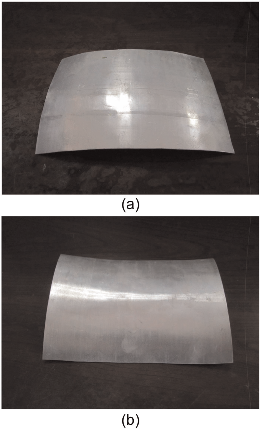
Experimental photographs: (a) convex parts and (b) saddle parts.
Plastic forming process for flexible rolling is complex, which includes large deformation, geometric nonlinearity, material nonlinearity and contact nonlinearity, so the explicit dynamic analysis software ABAQUS/Explicit has been applied to the simulation. In the forming process, some plate regions are pressed, which leads to thickness thinning and longitudinal elongation, and the stress and strain distributions in the thickness direction have an impact on the whole sheet forming, so there must be some nodes and elements in the thickness direction and that was the reason why solid elements were chosen to create the simulation model. The C3D8I, the eight-node linear brick and incompatible modes, is suitable for the analysis of flexible rolling. The accurate displacement, stress of the elements in small distortion and the result of the elements to the secondary bending problems could be solved effectively using C3D8I; meanwhile, the simulation cost is significantly reduced.
In the numerical simulation process, the rolls are arranged as an approximate arc array to be consistent with the rule effectively. The forming rolls can be bent in a small range. The bending degree of the rolls could be greater with the increase in the roll length. However, if the whole flexible rolls are used to create the model in the simulation, they cannot achieve the rotation because the bended long rolls cannot rotate around their axis. In order to make the modeling process simple and effective, the numbers of discrete and rigid short rolls (5 mm) along the axial alignment are used to substitute the whole rolls. The situations of finite simulations are shown in Figure 6. The contact between the rolls and the plate is set as a general one in order to define the interactions in software. It is allowed to define a contact very simply to assign the contact algorithm and the effect surfaces. The software itself can ascertain interaction surfaces automatically, and it has fewer restrictions on their types. Owing to the surfaces ought to be sticking and the formulation permits an elastic slip for them, the penalty friction formulation is adopted. According to the engineering experience, the friction coefficient between the steel and the soft steel is 0.1–0.2; and 0.2 is selected for this study. The “hard” contact of the latter is chosen to ensure the separation of the two surfaces when the normal pressure is zero or negative in the interacting process.
Finite element simulation: (a) convex parts and (b) saddle parts.
Shape analysis
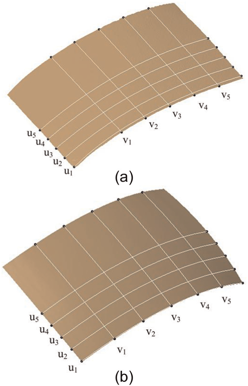
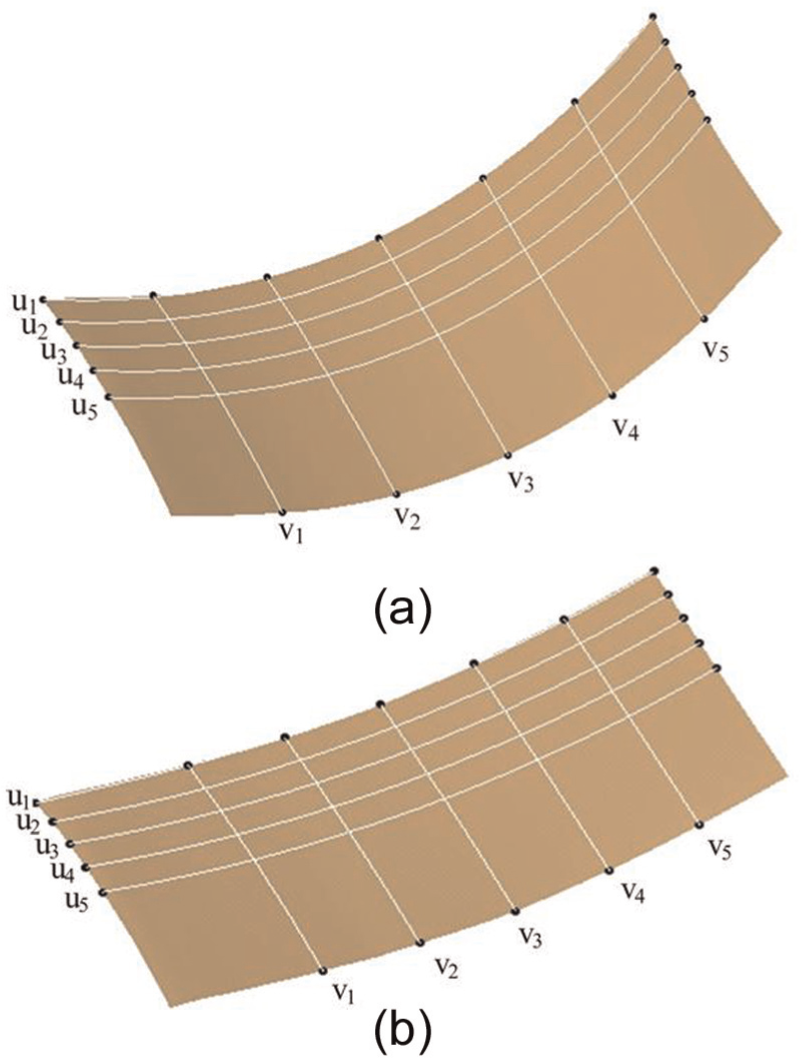
Many curves in the longitudinal and transversal directions are selected to analyze the formed parts for shape analysis. According to the theory above, five curves at different positions in transversal direction are measured from the simulation result and the actual formed part. The measured data are applied to plot the bending trends in transversal cross section and analyze the deviation of the thickness. Five curves at different positions in longitudinal direction are selected equidistantly, which are measured from the simulation result and the actual formed part. The measured data are used to plot the bending trends in feeding direction and calculate the longitudinal radius of the formed parts. Then, the theoretical, simulation and experimental results are compared.
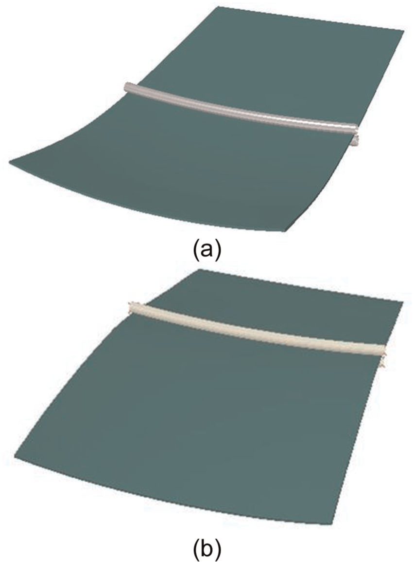
Selected curves can be measured conveniently in the simulation results, but difficult to be measured in the actual formed parts. Using 3D scanning system to scan the formed surface parts, point clouds of the formed parts can be obtained and merged to construct 3D surface as shown in Figures 7(b) and 8(b).
The results of convex parts: (a) simulations and (b) actual situation.
The results of saddle parts: (a) simulations and (b) actual situation.
Transverse shape analysis
Two kinds of transversal curves are selected as shown in Figures 7 and 8. There are five curves of the transverse curvature from v1 to v5. According to the above theory, the curvature radius is described as the degree of transverse bending. Known from the geometric relationship, the radius is related to the arc length, so it is necessary to find the measured arc length. Assuming that
where
The bending trend of convex parts in transversal direction.
The bending trend of saddle parts in transversal direction.
As shown in Figures 9 and 10, when the bending radius is certain, the change in transversal curvature radii is small in five different positions. Since rolls are arranged as an approximate arc array, deformation in the transversal direction is axisymmetric. The upper roll radius of convex part is smaller than that of the lower roll, and the upper roll radius of saddle part is smaller than that of the lower roll. When reduction is a certain value, the central thinning value of the convex part is 0.02 mm, while that of the saddle part is 0. It explains that the bending degree of convex part is obvious. Owing to the elastic deformation and the error existing in the actual rolling process, the curvature of the actual result is smaller than that of the simulation result. There is no obvious inflection point in the transversal curve, which shows that the smoothness of transverse deformation is better. Because the curvature of transversal curves is similar in different positions, it is proved that the effect of the continuous forming by flexible rolling is good.
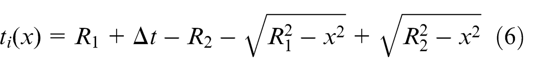
The upper and bottom surfaces of the actual formed parts are scanned. Applying the upper surface as the reference surface, the half width of the sheet metal is used for deviation analysis. Thickness deviations are obtained as shown in Figure 11, which is the deviation of thickness from the upper surfaces to bottom surfaces. Theoretical value curve is the thickness deviation of variation curve by calculating equation (6). Other five curves are the curves of thickness deviation at different positions in transversal direction, which are measured from the actual formed part. Because of the sheet metal horizontal symmetry distribution, this study used half of the plate width to perform comparative analysis, and the measurement range is 60–120 mm.
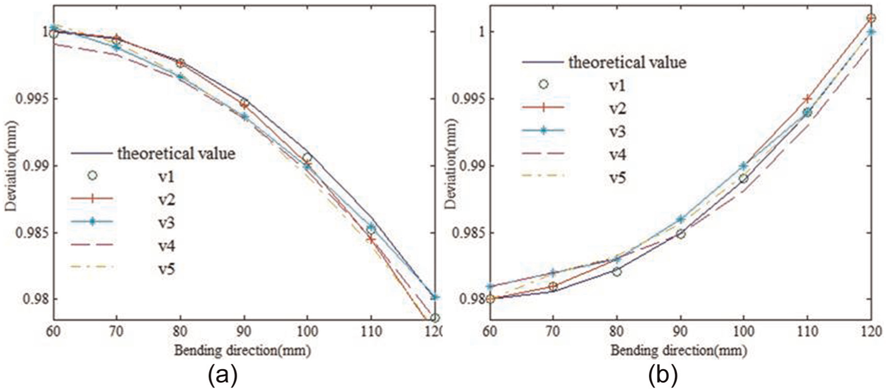
Deviation analysis: (a) convex parts and (b) saddle parts.
Owing to springback, stress accumulation and the error existing in the actual rolling process, the formed parts have some deviation values in the thickness direction. The thinning area of the convex parts is mainly concentrated on the middle of the sheet metal and not obvious in the edges, that is, the thinning value presents a decreasing trend from the middle to the edge. Conversely, the thinning area of the saddle parts is mainly concentrated on the edges and the central thickness of the sheet metal is almost unchanged, that is, the thinning value shows an increasing trend from the middle to the edge. Because sheet metal is thin enough, deviation values are in the reasonable range and there are no obvious inflection points in the curve of deviation analysis. The transverse bending is smooth relatively and not concave–convex, and the influence of the thickness deviation is small, so deviation values of the five curves float around the theoretical value, which indicates that the results of the flexible rolling method are effective.
Longitudinal shape analysis
Two kinds of longitudinal curves are selected as shown in Figures 7 and 8. There are five curves in the longitudinal direction from u1 to u5. According to the theory mentioned above, the upper surface of the formed parts is measured and calculated to obtain the trend in the feeding direction as shown in Figures 12 and 13.

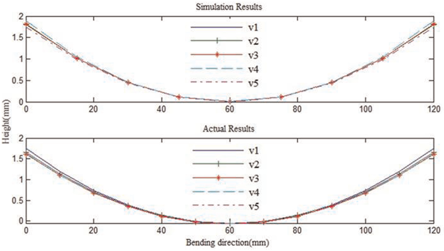
The bending trend of convex parts in longitudinal direction.
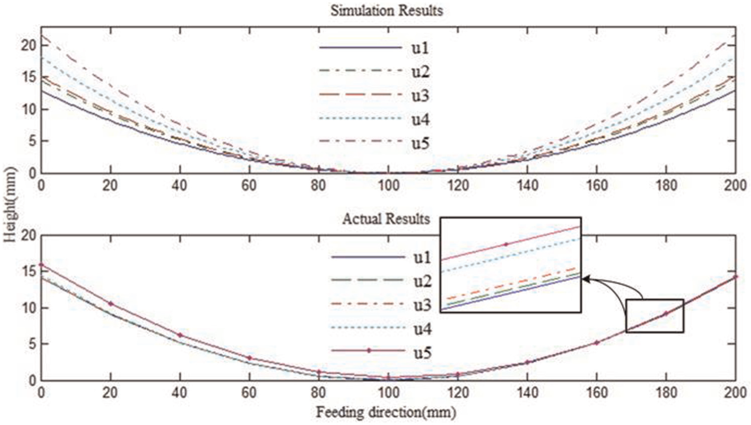
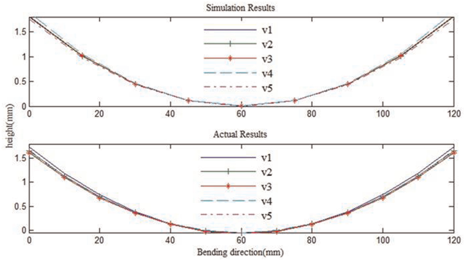
The bending trend of saddle parts in longitudinal direction.
In actual flexible rolling process, the contraction in transversal direction, accumulation in longitudinal direction and other factors appear with an increase in the sheet metal length; at the same time, the degree of bending is reduced. In other words, the longitudinal curvature decreases with the increase in the length of the sheet metal. In the simulation results, the curvature in longitudinal direction is idealized. The trends of the variation are consistent with the simulation results, reflecting that the arc length of the convex part in the longitudinal direction has the biggest value in the middle of the sheet metal and increases in the transversal direction monotonically from the center to the edge, and the situation is reversed for the saddle parts. Similar to Figures 9 and 10, for the convex part, the difference in five longitudinal extensions is large; it is proved that the curvature in the longitudinal direction is big; for the saddle part, elongation is distributed uniformly, which shows that the curvature in the longitudinal direction is small. The researches above illustrate the correctness of flexible rolling method.
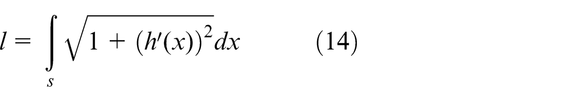
By selecting arcs in the feeding direction as many as possible, the arc lengths are solved by equation (14), and the values of longitudinal curvature are also calculated by equations (12) and (13) to analyze the changes in the radii. The half width of the sheet metal is used for the radius analysis as shown in Figure 14. For example, to get the longitudinal curvature of the saddle part in simulation, we select an arc in the simulation result and calculate it by equation (14); 206.246 mm is obtained as the result (
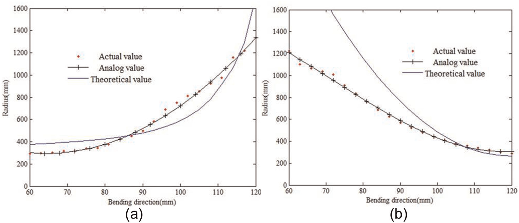
Analysis of the curvature: (a) convex parts and (b) saddle parts.
Theoretically, the variations in the longitudinal radius are different from the middle to the edges: the trend of convex surface part increases and the saddle part just decreases. Because of plastic deformation, thickness accumulation, springback and other factors, the experimental and simulation values deviate from the theoretical value within a certain range. Compared with the simulation and actual parts, the trends of curvature radius are consistent, and the actual results are close to the simulation. Owing to the interactions among the different elongations at the adjacent positions of the formed parts, the radius of curvature fluctuates, so the actual results are distributed evenly in the vicinity of the simulation results, but significant inflection point is not present. It shows that the flexible rolling method can achieve continuous forming effectively.
Conclusion
Flexible rolling uses flexible rolls to form the uneven roll gap and carries out continuous and flexible forming for 3D sheet metal parts. A large forming area and high efficiency can be obtained by using this method.
The shapes of formed parts are analyzed to work out the relationship between the two directions. The calculation method of transverse thickness and longitudinal radius of curvature has been deduced on this basis. The influence factors of formed parts include roll bending radius, pressure ratio, sheet metal width, thickness and so on.
The roll discretization method is adopted in the numerical simulation modeling, and it is effective to solve the problem that the whole bending rolls cannot rotate around the bending axis.
The trends of different kinds of parts in two directions are discussed by comparing the changes in different double-curved parts. The comparison between the simulation and actual results shows that the flexible rolling method is to comply with the algorithm results.
The forming apparatus is proposed to complete forming experiments. The formed parts can be obtained effectively, and the results show that the effect of flexible rolling forming is favorable, and the flexible rolling method is feasible and practical.
Footnotes
Appendix 1
Declaration of conflicting interests
The authors declare that there is no conflict of interest.
Funding
This work was financially supported by the National Natural Science Foundation of China (No. 51275202).