
Abstract
The major source of environment and economic impact of machine tools has been attributed to their energy consumption. This article, therefore, proposes a novel energy mapping approach to evaluate specific cutting energy consumption with respect to cutting parameters. Unlike the studies presented earlier, which are machine-tool-specific, this study focuses on the basic tool–workpiece interaction for energy consumption analysis. The presented energy map reveals different energy consumption regions at varying machining parameters (feed and speed) during orthogonal machining of Al 6061-T6 alloy. The chip formation analysis indicates a strong correlation with the different energy consumption regions identified on the energy map. It has been observed that feed is the major contributing factor towards shear plane angle during chip formation as compared to cutting speed. Therefore, increasing feed results in a higher shear angle and consequently lowering the specific cutting energy as indicated on the energy map. Selection of machining parameters corresponding to the lowest specific cutting energy consumption region, as identified on the energy map, can result in energy savings up to 27% per kg of material removed. The developed map can be used for selection of suitable energy-efficient cutting parameters.
Keywords
Introduction
Globally, there is a concern over the depletion of conventional energy resources with studies suggesting the oil production having reached the peak between the years 2004 and 2012. 1 As a result, the urgency for the manufacturing sector to develop and implement energy-efficient material processing techniques is greater than ever.2–6 Therefore, the last few years have witnessed a rise in research related to the understanding of the environmental impact of different manufacturing processes.6–10 Machining is one of the most important and widely used manufacturing processes with the companies in United States alone spending more than US$100 billion on machining annually. 11 Like other manufacturing processes, machining is also being investigated from the perspective of its impact on the environment.12–14 A vital element of environmentally sustainable machining is the careful use of natural resources. Therefore, the materials and the energy consumed in the machining process are the two major concerns. The sustainability performance of materials can be enhanced using abundant and easily recyclable materials. In this regard, aluminium alloys are most environmentally sustainable materials, followed by steels, stainless steels and titanium alloys. 15
With regards to energy consumption in machining processes, environmental assessments have identified that more than 90% of their environmental impact is due to electrical energy consumption. 16 Therefore, analysis and subsequent reduction of electrical energy usage in a machining process is expected to yield both environmental and economic gains. Reduction in electrical energy consumption of machining processes can be achieved either by development of energy-efficient machine tools or by optimizing existing machining processes. 2 While the first approach involves a change in machine tool design and development methods as well as high initial costs, the second approach can be implemented with relative ease and lesser resources. 17 Based on published literature, the strategies for optimization of existing machining processes can be broadly classified into two categories: modelling of energy consumption of machine tools18–27 and optimization of machining process parameters.28–42 The former focuses on developing mathematical models to describe the energy consumption process of a machine tool, whereas the latter is concerned with obtaining the optimum setting of process parameters (speed, feed and depth of cut) which would result in minimum energy consumption.
Energy consumption modelling of the machine tools is primarily centred on its operating states. Depending upon the operational characteristics, two states of machine tools can be defined: basic state and cutting state. 18 During the basic state, electricity is consumed to bring the machine in operation-ready mode, whereas, in the cutting state, electricity is consumed in removing the workpiece material. Gutowski et al.19,20 used the exergy framework to mechanistically model electrical energy consumption of machine tools in the basic state and cutting state. A modern machine tool is a complex system composed of numerous electrical and mechanical interconnected sub-systems working in coordination with each other during its different operational states. A detailed energy consumption study involving the different components of machine tool such as spindle, servo motors, tool changer and coolant pumps was done by He et al. 21 This study was extended by incorporating the machinability of workpiece in the energy model by Aramcharoen and Mativenga. 22 However, systems and sub-systems of a machine tool are susceptible to losses, and behaviour of machine tools in terms of energy consumption is complex and is still a topic of ongoing research. 23 Therefore, empirical methods are often used to augment the energy consumption models of machine tools.18,23–26 Energy modelling provides reasonable information about the energy consumption by taking into account the different components of a machine tool. However, there are some limitations associated with such energy models. First, such models are essentially unique for every make and type of machine tool. Second, energy modelling can become tedious in case of empirical models that require calculations of statistical model coefficients. These complexities can limit the use of energy models at shop-floor level.
Optimization of machining process parameters is another strategy to minimize energy consumption in existing machining processes. Optimization studies incorporate objectives such as, energy minimization, power minimization and cutting fluid minimization. These objectives are either investigated alone or in combination with other traditional objectives such as surface finish, tool life and tool wear. For single objective functions, optimization techniques such as Taguchi methods28–33 and response surface methodology (RSM)30,34,35 are mostly used. For simultaneous optimization of multiple objectives, techniques like grey relational analysis36–38 and composite desirability analysis 39 are often used in combination with Taguchi methods or RSM. Recently, genetic algorithm–based multi-gene genetic programming 40 and teaching-learning-based optimization algorithms 41 have been used to analyse the environmental impact of machining. Generally, optimization studies target a particular combination of cutting tool, workpiece material and machine tool. Involved statistical computations are required in optimization methods which might discourage their use on shop floors. With the exception of a few studies, majority of the optimization studies have used cutting power instead of specific cutting energy (SCE) as an objective to be minimized. Cutting power is a machine-tool-specific variable which varies from one machine to another. Cutting power and SCE are conflicting objectives, and optimum settings for both are entirely opposite. Unlike SCE, cutting power doesn’t incorporate the material removed and hence it is not an appropriate variable for expressing the environmental impact of a machining process. 33 The cutting conditions used in optimization studies are usually in the conventional or low-speed machining range. In the two studies of Camposeco-Negrete,33,35 energy minimization was done through optimization of cutting parameters during the turning of Al 6061-T6 alloys. Both of these studies were limited to low cutting speed ranges of up to 250 and 434 m/min, respectively. For an alloy like Al 6061 which has a high machinability rating, 43 usage of higher cutting speeds could have provided valuable insights into the energy consumption in relation to high-speed machining.
It is evident from the preceding discussion that majority of the energy-analysis studies are machine-tool-specific and they disregard the basic interaction between tool and workpiece. The energy required to remove per unit volume of material (SCE) depends upon the machinability of work material and cutting conditions, and therefore, it can be easily controlled by the machine tool end user through careful selection of machining parameters. 44 Up till now, there exists no study that comprehensively investigates the relationship of SCE with cutting conditions while utilizing the orthogonal machining approach for basic tool–workpiece interaction. This article attempts to bridge this knowledge gap and presents a novel energy map approach to study the SCE consumption in orthogonal machining of Al 6061-T6 alloy using uncoated carbide tools. Aluminium is the most widely used nonferrous metal, being second only to steel in world consumption. 45 Aluminium alloys that are most commonly used in manufacturing of machine element are from 2xxx and 6xxx series alloys. 45 The most easily machined aluminium alloy is Al 2011-T3 and is often referred as free-machining aluminium alloy. 46 Al 7075 is the most widely used alloy from 7xxx series and finds extensive application in aerospace industry. The most versatile series of aluminium alloys is 6000 series and Al 6061 is the most widely used alloy in this series. 47 Al 6061 alloy has good machining properties and is an attractive choice for aerospace, automotive and high-tech applications. 48 Owing to its high relevance with industrial sector, aluminium alloy Al 6061-T6 has been used in this research.
The developed energy map based on the orthogonal machining approach can be utilized further towards the modelling of metal cutting process with emphasis on energy consumption. The energy map presented here is unique since it populates the actual energy expended in the metal cutting process while excluding the machine-tool-specific energy consumption data. It can therefore be used as a basic instrument for identifying various regions characterized by SCE consumption. The trends observed in the formation of different SCE regions have been correlated with the mechanics of chip formation and the chip–tool contact length phenomenon. The developed energy map is similar in construction to the process maps developed by earlier researchers. While the methodology of using contour maps has extensively been researched and well reported by past researchers, the approach has largely been employed for the construction of wear maps and wear mechanism maps.49–56 Other researchers have used this approach for the analysis of surface quality and bur formation.57–59 The use of contour plots for energy consumption during machining has recently been reported for milling carbon steel 17 and turning of Al 6061. 33 However, in both the cases, total machining energy was recorded and analysed, rendering the results machine-tool-specific. This research attempts to investigate the energy consumption through basic tool–workpiece interaction by utilizing the orthogonal machining approach. The developed SCE map is easy to use and has the potential to serve as a simple visual guide in selecting the energy optimum cutting parameters during process planning as well as on the shop floors. The developed energy map has the potential to be used to identify areas for future research in terms of cutting tool development, chip formation and tribology in metal cutting.
Experimental details
Selection of machining parameters in this research has been based on the detailed literature survey. Several factors can affect a machining process, such as tool geometry (nose radius and rake angle), cutting fluids and cutting parameters (speed, feed and depth of cut). 43 The research on the impact of these factors on energy consumption during the machining processes is still in its infancy. Therefore, more studies are required to understand the influence of machining parameters on energy consumption in machining processes. 38 Li and Kara 23 reported the insignificant impact of tool nose radius and rake angle on power consumption during a turning process. Similar effect of tool nose radius on power consumption was also reported in other studies.30,39 Cutting fluids have a positive effect on productivity of machining operation, surface quality and tool life; 60 owing to the environmental and health hazards associated with conventional cutting fluids, they are not suitable for sustainable and cleaner production. 31 With regards to the cutting parameters, cutting speed has been observed to have relatively less effect on energy consumption33,35 as compared to the effect of feed on energy consumption.33,35,61 Depth of cut has also been observed to affect energy consumption.33,35 From viewpoint of industrial importance, cutting speed and feed are most significant as they greatly influence critical responses such as tool life, surface roughness, production time, cutting temperatures and forces.28,29,39,43,62–65 Cutting speed and feed are easily controllable factors on the shop floor without having any impact on the dimensional parameters of the workpiece.
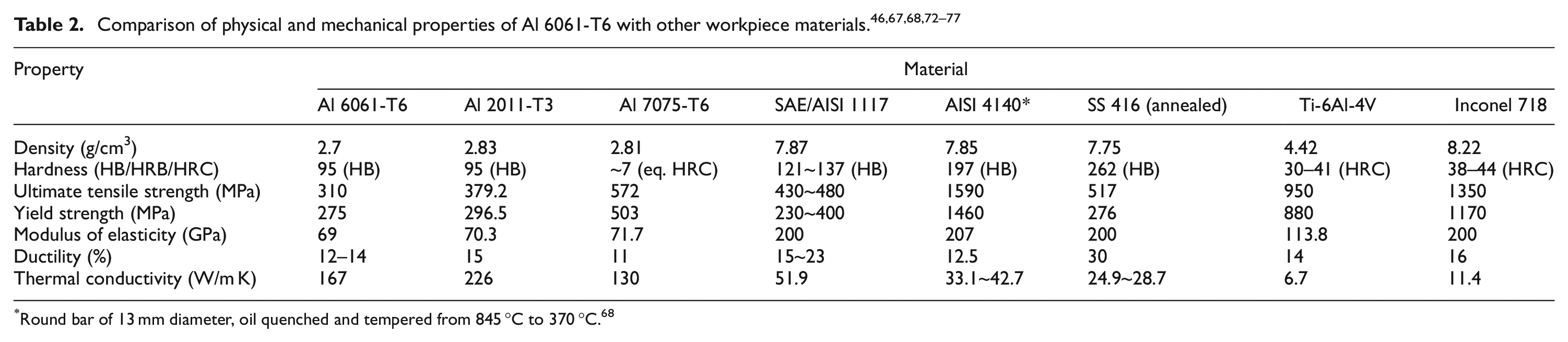
Aluminium alloy Al 6061-T6 pipes having outer diameter of 200 mm and a wall thickness of 4 mm were used as the workpiece in this study. Tables 1 and 2 present a brief comparison of chemical composition and mechanical properties of Al 6061-T6, the workpiece material used in this research, with other prospective materials that are important from the viewpoint of different industrial sectors such as automotive, process engineering and aerospace.
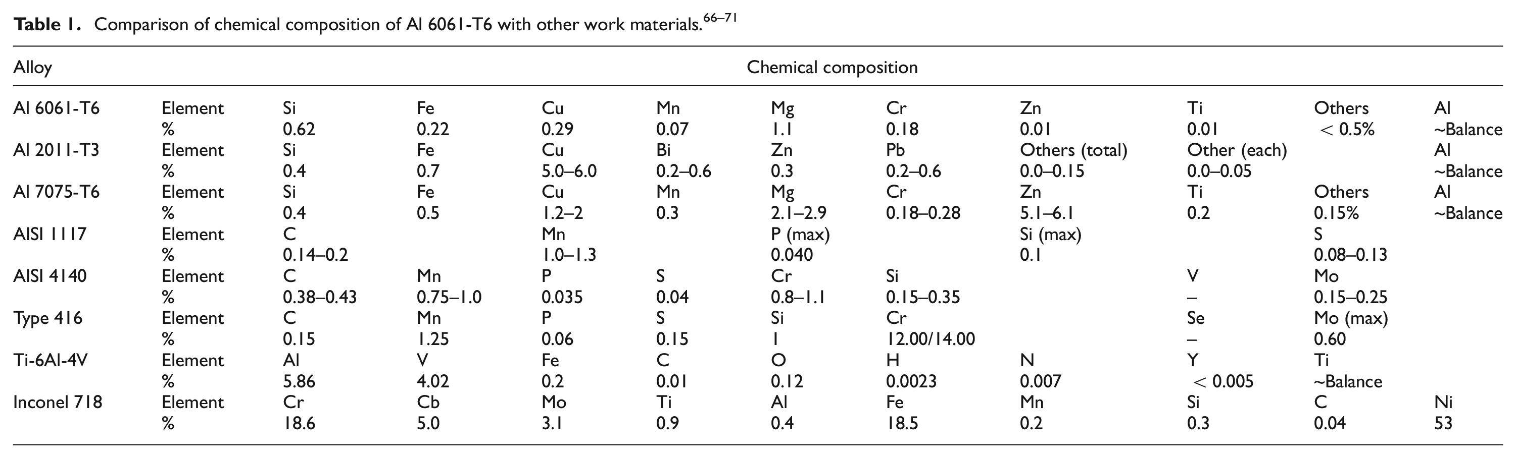
Round bar of 13 mm diameter, oil quenched and tempered from 845 °C to 370 °C. 68
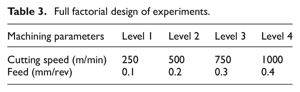
Uncoated plain cutting inserts CCMW 09 T3 04 H13A with 0° rake angle and without chip breaker have been used for all experimental tests. All the tests were done under dry cutting conditions on ML-300 computer numerical control (CNC) Turning Machine manufactured by YIDA Precision Machining Company, Taiwan. The CNC machine had total power capacity of 26 kW with the spindle motor of 15 kW and a coolant pump of 860 W. The spindle could achieve a maximum speed of 3500 r/min. Orthogonal tube turning method was employed in this study for simulating orthogonal machining. The actual experimental setup is shown in Figure 1. It can be observed that the cutting tool was perpendicularly fed to the workpiece and the length of the cutting edge of cutting tool (9 mm) was also greater than the pipe thickness (4 mm), thereby fulfilling the mandatory conditions for orthogonal machining. 78 Owing to the orthogonal nature of cutting process, cutting speed and feed were chosen as the cutting parameters. Four levels each of cutting speed and feed were chosen within the permissible range recommended by the supplier of the cutting tool. In order to obtain a detailed information about energy consumption in relation to cutting conditions (cutting speed and feed), full factorial design of experiments was chosen (Table 3). Each experiment was repeated three times. A fresh insert was used in each experimental run in order to eliminate the effect of tool wear on energy consumption of the machining process.
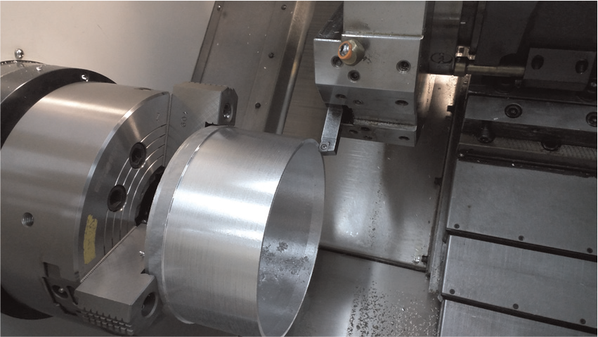
Actual orthogonal machining setup.
Full factorial design of experiments.
The power measurements during all the experimental runs were done at the main bus of the machine with Yokogawa clamp-on power analyser CW 240-F. The analyser could instantaneously measure and log a variety of responses such as power, current, voltage and power factor and had the measurement interval of 0.1 s. Idle power of the machine (Pidle) was measured when all of its components like motors, drives and pumps were electrically energized and the machine was ready to perform the cutting operations. Spindle was not turned on in this state as its revolutions per minute depended upon the unique cutting conditions that were to be specified in the CNC program for each experiment. In accordance with the methodology developed by Li and Kara, 23 two-cycle approach was used for each experimental run. The first cycle was air-cut cycle and the second was actual-cut cycle. For each cycle, average power consumed was measured and recorded as Pair and Pactual, respectively. The difference between Pair and Pactual provided the power necessary to remove the material (Pcut) during a particular machining cycle as shown in equation (1)
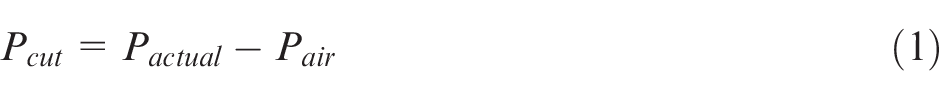
The data for air-cut and actual-cut power measurements were taken only when the tool and workpiece were engaged. Therefore, the power consumed in rapid and feed movement of slides and acceleration and deceleration of spindle before and after the length of cut were excluded from the cutting power Pcut. Material removal rate (MRR; mm3/s) for orthogonal pipe machining was calculated as shown in equation (2)

where ‘v’ is cutting speed (m/min), ‘b’ is the width of cut (mm) and ‘f’ is the feed (mm/rev). In all the experiments, tool nose was not involved in the cutting process and all the cutting was performed through the cutting edge of the insert.
Power consumption during machining was normalized over the MRR to obtain ‘unit power’ or specific energy. Specific energy is the energy consumed in removing per unit volume of material and is more meaningfully expressed in the units of N m/mm3 or J/mm3. 43 Based on the actual-cut power (Pactual), cutting power (Pcut) and MRR, specific total energy (STE) and SCE were calculated as shown in equations (3) and (4)


STE is based on actual-cut power and is highly dependent upon the make and type of machine, for example, a machine with big spindle and slide motors would consume more electrical power to remove a certain amount of material as compared to a small machine tool. Furthermore, the effect of efficiencies of motors and drives in a machine tool will also affect the values of STE. Minimization of STE and its variants can be found in literature,17,24,33,61 but such studies are inherently machine-specific and the results cannot be applied to other machine tools. However, SCE doesn’t take into account the make, type and efficiency of different components of the machine tool and incorporates only Pcut, the power required to remove unit volume of certain materials (Al 6061 in this case). It might be argued that considering only SCE and excluding the effect of machine tool (STE) would not encompass the overall impact of machining process on environment, but given the situation that there are various unique brands of machine tools available globally, the results obtained using STE on one machine tool couldn’t be applied to others. Typically, SCE was found to range anywhere between 26% and 75% of the STE consumed during the machining process at different cutting conditions as shown in Figure 2. It can be observed from the figure that the value of SCE as the percentage of STE tends to increase as the values of cutting speed and feed are increased, making the machining process more energy efficient.
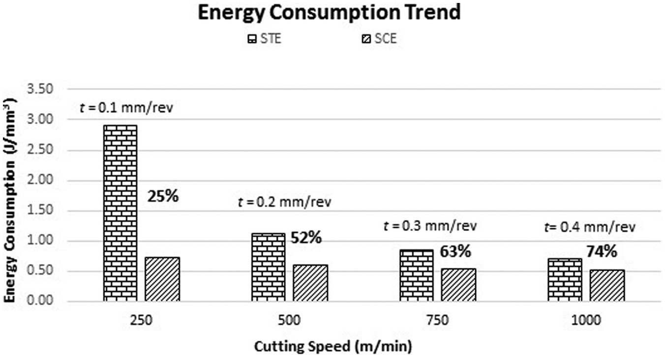
SCE as percentage of STE at different cutting condition.
Results
SCE during machining
SCE is the energy consumed in removing per unit volume of material. Table 4 presents the typical values of SCE for aluminium and its alloys as reported in literature.
Values of specific energy as reported in literature.
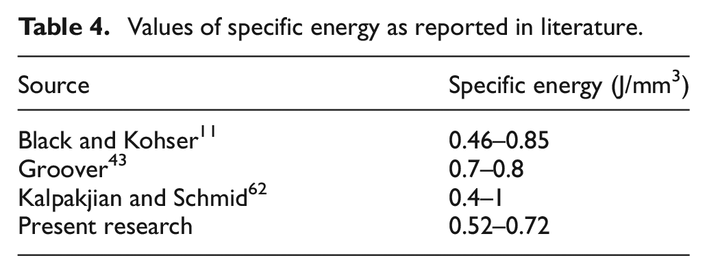
It can be seen that the SCE obtained in this research is well consistent with those reported in literature11,43,62 for fresh tool (sharp cutting edge) and undeformed chip thickness of 0.25 mm. In the case of orthogonal pipe machining used in this research, a fresh cutting insert was used for each experimental run; therefore, the condition of sharp tool was perfectly fulfilled. Furthermore, in case of orthogonal machining, the feed and undeformed chip thickness are same. 11 High values of feed up to 0.4 mm/rev were used in this research as compared to 0.25 mm reported in literature which might have contributed to the slight difference between the published and obtained values of SCE.
Development of energy map
A novel concept of energy maps for orthogonal machining of Al 6061-T6 alloys using H13A inserts has been presented in this research. The methodology used to construct the energy consumption map is purely experimental. In this context, extensive cutting tests were conducted to populate the map. Each condition was repeated three times in order to establish repeatability of the results being presented (the percentage standard error was found to be in the range of 0.14%–5%). Full factorial experimental plan (Table 3) was used to provide initial 16 experimental combinations of varied cutting speed and feed. The SCE for all the experiments was evaluated and plotted on a feed–speed grid. Based on the plotted SCE values, different regions characterized by energy consumption were identified. The identified regions were refined by performing additional experiments. In addition to the initial 16 experimental conditions, 56 other cutting conditions were tested for the construction of energy map.
Figure 3 shows an energy map developed for orthogonal machining of Al 6061-T6 alloy. The figure is presented as a contour plot, which is a graphical technique for representing three-dimensional (3D) surfaces by plotting constant z slices which represent different regions of energy consumption. These regions are characterized as very high (>0.7 J/mm3), high (0.625–0.7 J/mm3), moderate (0.55–0.625 J/mm3) and low (<0.55 J/mm3) SCE consumption values. The selection of these regions and their representative values was made on the basis of comparison of experimentally obtained values with those reported in literature (shown in Table 4). High values of SCE have been observed to exist at low values of feed. The reduction in MRR due to low feed was significant and not proportional to the corresponding reduction in electric power consumption. This resulted in overall increase in SCE. Conversely, favourable regions characterized by low SCE consumption have been observed to exist at higher feed rates. A significant reduction in SCE consumption (ranging between 15% and 28%) has been observed with the increasing feed. However, a reduction in SCE of the order of 6%–13% has been observed with the increase in cutting speed. The significance of feed and relative insignificance of cutting speed on energy consumption has been reported in literature for Al 6061 alloys at low cutting speed range (up to 250 and 434 m/min).33,35 However, the results presented in this research show the dominant effect of feed and relatively less important effect of speed on SCE at higher cutting speeds of up to 1000 m/min. Generally within the different energy consumption regions, the value of SCE has been found to reduce as the feed and cutting speed increase; therefore, high feed coupled with high cutting speeds have resulted in very low SCE consumption.
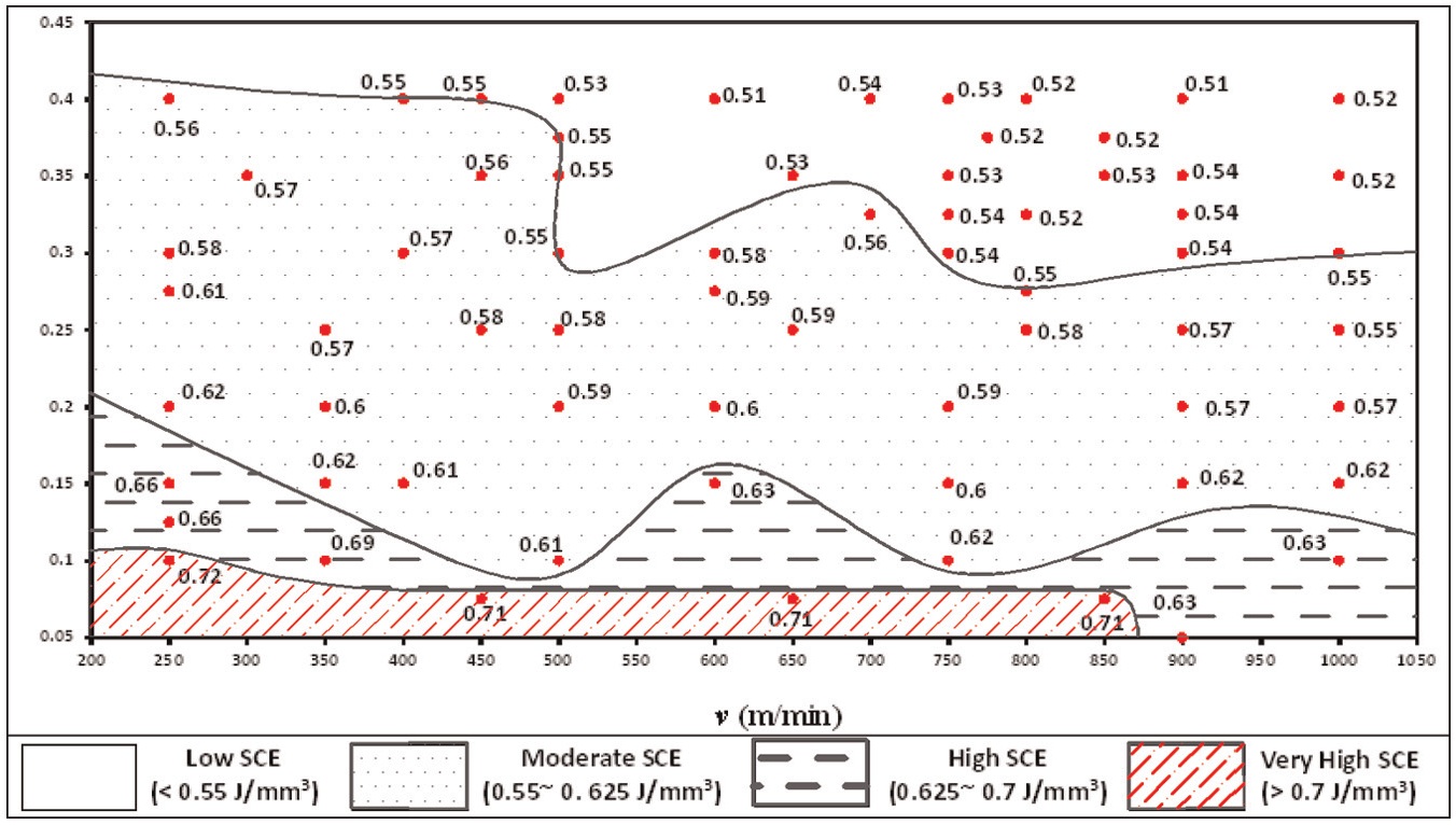
Energy consumption map of aluminium alloys Al 6061-T6 using uncoated H13A tools (cutting speed range of 250–1000 m/min and feed range of 0.1–0.4 mm/rev).
Very high SCE consumption region (>0.7 J/mm3) or region of avoidance has been observed at low feed with low–medium cutting speed. This region is observed to be associated with the feed up to 0.1 mm/rev in combination with the cutting speed up to 850 m/min. SCE dropped from very high (>0.7 J/mm3) to high energy (0.625–0.7 J/mm3) consumption region when the cutting speed was increased beyond 850 up to 1000 m/min, while keeping the same value of feed (up to 0.1 mm/rev). A high SCE consumption region (0.625–0.7 J/mm3) begins to form between the feed range of 0.1 and 0.2 mm/rev. As the cutting speed approached 500 m/min, the feed required for this region lowered to 0.1–0.15 mm/rev. The feed requirement for this region further lowered down to the range of 0.05–0.125 mm/rev when the cutting speed increased beyond 850 m/min. A trend similar to high SCE consumption region has been observed for moderate SCE consumption region (0.55–0.625 J/mm3). This region starts forming between the feed range of 0.2 and 0.4 mm/rev. But as the cutting speed is increased, the existence of this region is observed at a low feed range of 0.15–0.3 mm/rev. Low SCE consumption region (<0.55 J/mm3) has been observed between the feed range of 0.3 and 0.4 mm/rev at cutting speeds greater than 500 m/min.
The energy map provides a visual guide to process planners regarding the variation of SCE with cutting parameters. The final choice of suitable cutting parameters depends upon the quality characteristics required for the machining process and the permissible range of cutting parameters specified by the tool manufacturer.
Four different regions have been demarcated on the developed energy map based upon an upper- and lower-bound value of SCE. Each energy region identified on the map corresponds to a range of cutting speed and feed. For instance, energy consumption is expected to be low if the cutting speed is set beyond 500 m/min, and feed is set between 0.3 and 0.4 mm/rev (low SCE consumption region). The effect of setting cutting parameters on energy consumption becomes pronounced if large quantities of material are to be removed. The quantitative effect of variation of SCE with respect to different cutting conditions can be demonstrated by comparing cutting energy consumed in removing 1 kg of Al 6061-T6 alloy (measured as kJ/kg). In order to obtain a meaningful comparison of energy expended, SCE values obtained within each region have been averaged and converted to kJ/kg from J/mm3 using appropriate value of density. 67 Figure 4 shows the difference between the cutting energy consumed in removing 1 kg of Al 6061-T6 alloy when cutting conditions (cutting speed and feed) are set within the range corresponding to different energy regions. It can be observed that substantial energy savings up to 27% can be achieved per kg of material removed by appropriate setting of cutting parameters. The economic and environmental benefits of this saving become important if the large production quantities are considered.
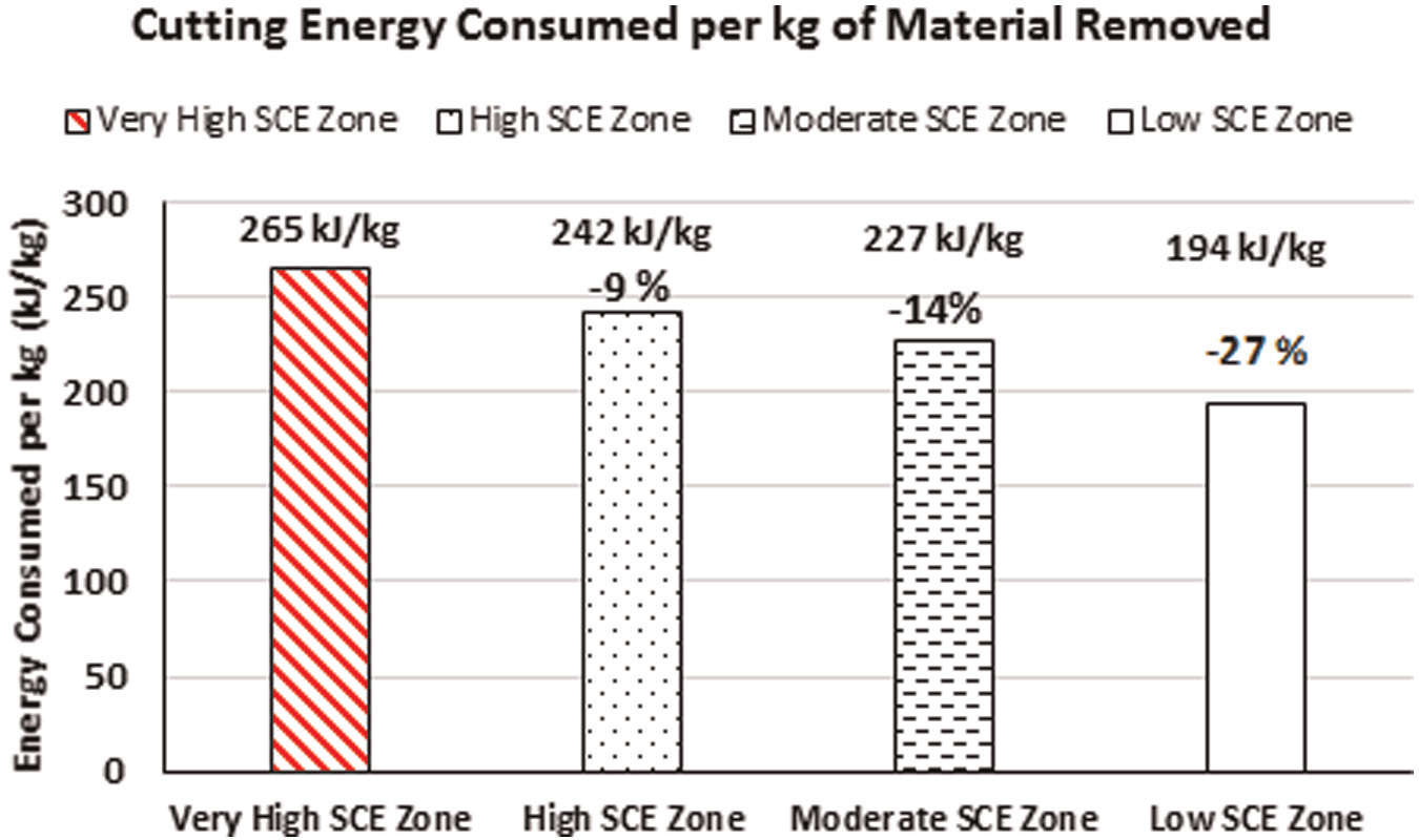
Cutting energy consumed in removing per kg of Al 6061-T6 Alloy.
Discussion and analysis
The formation of different energy zones in the energy map and the impact of cutting speed and feed on energy consumption in a machining process can be related to the mechanics of cutting process. Therefore, mechanics of chip formation in orthogonal cutting process and the interaction of cutting tool and chip has been analysed to develop better understanding of developed energy consumption map.
Mechanics of chip formation
In case of orthogonal cutting, workpiece is assumed to be plastically deformed or sheared along a well-defined shear plane to form the chip. This shear plane is oriented at shear angle


Undeformed chip thickness (t) and feed (f) are same in orthogonal pipe machining.
79
Actual average chip thickness was accurately measured by grinding and polishing the chip samples and analysing them under metallurgical microscope. Figure 5 shows the optical images of some of the chips produced during the orthogonal machining at various cutting conditions. The experimentally obtained average chip thicknesses were used to calculate chip thickness ratio

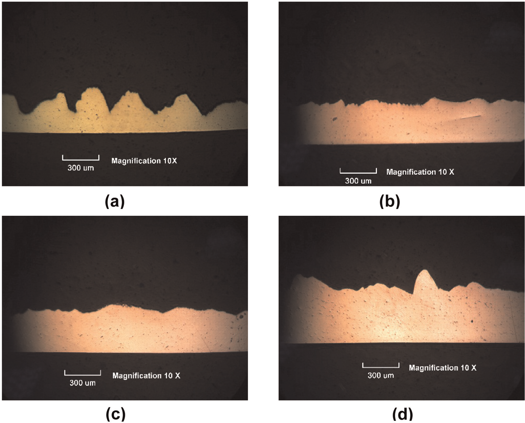
Microscopic images of chips at different cutting conditions: (a) v = 250 m/min, f = 0.1 mm/rev; (b) v = 500 m/min, f = 0.1 mm/rev; (c) v = 750 m/min, f = 0.2 mm/rev and (d) v = 1000 m/min, f = 0.2 mm/rev.
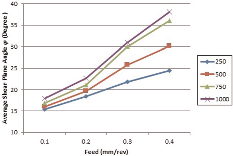
Effect of feed on average shear angle
For cutting tool with 0° rake angle, shear strain
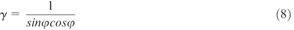
Shear stress
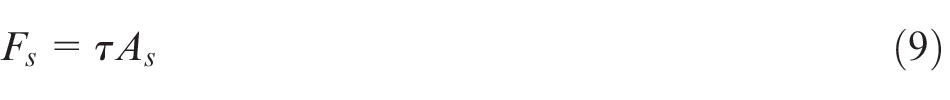
where shear plane area
From equation (9), the force required to form the chip depends upon the shear yield strength of the work material under cutting conditions and the area of the shear plane. Shear yield strength of metals can be approximated to remain constant or vary slightly under different cutting conditions.43,79 For aluminium alloys, this strength can be approximated as 97 N/mm2. 79
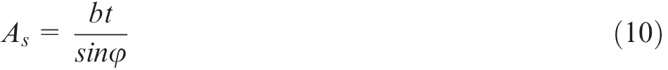
The graph in Figure 7 shows the effect of feed on approximated theoretical specific shear energy
Effect of feed on theoretical specific shear energy at different cutting speeds.
It is important to mention here that the theoretical specific shear energy
Tool–chip contact length analysis
During orthogonal cutting, the chip is formed at the shear plane which flows over the tool rake face and remains in contact with tool over a certain distance. This distance is referred to as tool–chip contact length, or, simply, contact length
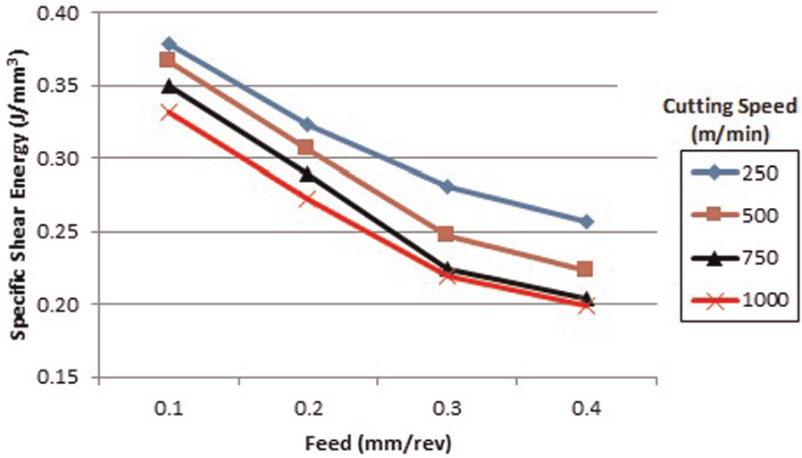
In this research, Sandvik-supplied plain inserts of H13 grade were used and the factors like tool geometry, workpiece material, tool material and cutting environment were not varied. Hence, the factors that could affect the chip–tool contact length were cutting parameters (speed and feed). It has been reported during machining of various alloys that contact length tends to reduce as the cutting speed is increased.83,86–88 However, increase in feed is reported to increase the contact length.83,86,88 The effect of cutting parameters on contact length and consequently on heat transfer and energy consumption can be used to describe the SCE consumption in the energy map.
Cutting inserts after each experiment were analysed with a metallurgical microscope equipped with image processing software. Interfacial tracks or contact tracks on the insert rake face can be used to measure the chip–tool contact length.87–90Figure 8 shows the effect of cutting speed on contact length at different feeds during orthogonal cutting of Al 6061-T6 alloys. It is observed that contact length increases with the increase in feed and decreases with the increase in cutting speed. The trends observed for contact length in relation to cutting speed and feed are consistent with the findings reported in literature.83,86–88 The decreasing trend in contact length with increasing cutting speed is of particular importance from the viewpoint of energy map proposed in this research. It can be observed from the energy map presented in Figure 3 that within each identified energy zones, there is a general decreasing trend in the SCE consumption with the increase in cutting speed. This reduction in SCE with cutting speed can be attributed to the reduction in tool–chip contact length. As the cutting speed increased, the contact length decreased, which in turn decreased the heat transfer between the tool and chip and the undesirable frictional forces. This led to a reduction in energy requirement for removing a unit volume of material. Although the reduction in SCE with cutting speeds is not substantial (about 6%–13%), it still possesses a potential that should be exploited for enhancing the sustainability of a machining process. Contrary to the cutting speed, high feed has resulted in large contact lengths which would have allowed greater heat transfer and in turn greater SCE requirement. This disadvantage of large contact lengths is offset by lower specific shear energy requirements at higher values of feed. Therefore, the SCE consumption has not been affected by the detrimental effect of higher feed on contact length.
Effect of cutting speed on contact length at different feeds for Al 6061-T6 alloy.
Conclusion
This research presents an energy map for SCE consumption in orthogonal machining of Al 6061-T6 alloys. This energy map has the potential to serve as a powerful visual tool that readily provides information to process planners/end users about the variation of SCE consumption with cutting conditions.
Cutting energy required to remove 1 kg of Al 6061-T6 alloy is reduced by up to 27% by appropriate selection of cutting parameters.
Feed is found to be the most influential factor, where 15%–28% reduction is observed in SCE consumption by increasing the value of feed from 0.1 to 0.4 mm/rev.
Increase in cutting speed from 250 to 1000 m/min reduces SCE consumption by 6%–13%.
Lower values of feed result in very high energy consumption region. This region is observed in the vicinity of feed of 0.1 mm/rev and cutting speed up to 850 m/min.
The minimum value of SCE consumption is observed between the feed range of 0.3 and 0.4 mm/rev at cutting speeds greater than 500 m/min.
Specific shearing energy at shear plane decreases by 32%–42% with the increase in feed. This results in lower SCE at higher values of feed.
Chip–tool contact length decreases with the increase in cutting speed. This reduced contact length facilitates a reduction in SCE as the cutting speed is increased.
Future work
Since reduction of energy consumption is of paramount importance for enhancing the sustainability of a machining process, the proposed energy mapping approach will prove itself to be a valuable addition in energy minimization strategies. The authors are currently working on enhancing the utility of the proposed approach by developing corresponding tool wear maps and linking them with the developed energy maps. Another potential area for research is cost optimization. The proposed process map can be extended to incorporate various cost levers such as tool cost, energy cost, direct and indirect labour cost and setup cost. This extended (cost-based) process map can be used to identify cutting conditions that will minimize total cost of machining operation. Furthermore, energy maps for other workpiece materials of industrial importance such as steels, titanium and Inconel alloys can be developed in future research works.
Footnotes
Appendix 1
Declaration of conflicting interests
The author(s) declared no potential conflicts of interest with respect to the research, authorship and/or publication of this article.
Funding
The author(s) received no financial support for the research, authorship and/or publication of this article.