
Abstract
Polymeric materials have been widely used to replace traditional metallic materials due to their high specific elastic properties. Even though polymeric materials can be produced as near net shapes, machining is still required to make the assembling of the final products. The selection of tool and cutting conditions is very important to machine plastics because of the high ductility and low melting point of the materials. In this study, the machining behaviour of high-performance engineering polymers, such as ultra-high-molecular-weight polyethylene, polyoxymethylene and polytetrafluoroethylene, has been investigated using a full-factorial design (design of experiment). The effect of the factors such as feed speed, spindle speed and drill point angle was identified for each of the response variables (circularity error, surface roughness (Ra) and thrust force (Ff)). The drilling mechanism was substantially affected by the physical and mechanical properties of the polymers. Different cutting set-up conditions were able to optimize the responses. The polytetrafluoroethylene exhibited better results, achieving lower circularity error, surface roughness and thrust force. In the opposite manner, the ultra-high-molecular-weight polyethylene exhibited a rough topography at low feed rate and spindle speed levels.
Introduction
Polymeric materials are widely used in several engineering applications, ranging from structural components for houses and buildings, to aerospace and miscellaneous objects. 1 A novel and relevant field of application of polymers is the medical area, like the design of orthesis and cartilage tissues. 2 The main attraction of polymers is related to their lightweight and moderate strength and easy moulding process. The moulded parts must be assembled (usually by drilling) to obtain a final product. Due to their low melting point, a significant body of research has been produced to investigate the machinability of these materials. A large number of parameters affect the quality of the holes, such as the cutting speed, feed rate, tool geometry and mainly the physical and chemical characteristics of the workpiece material.
The cutting process of polymeric materials differs in many aspects from the one typical of metals and their alloys. When the metallic materials are cut, high temperatures are reached at the tool–chip interface. The transfer of heat to the cutting tool is the main agent responsible for the deterioration of the cutting edge due to wear mechanisms (diffusion and oxidation). In contrast, lower temperatures are observed when polymeric materials are machined. However, even low temperatures are able to damage the workpiece material by the melting of the cutting edge path and consequent distortion of the final component. 3
The machining process of thermoset and semi-crystalline thermoplastic polymers must reach a specific temperature level (glass transition temperature) to avoid surface damages, given that the heat transfer can significantly affect the material’s microstructure. Fetecau et al. 4 reported that the temperature plays a vital role in the machining of plastic materials, as it influences directly the rate of tool wear and the final surface finishing of a workpiece material.
In the last decade, the problems associated with the precision and efficiency in cutting composites have become an important issue in the manufacturing industry. Several investigations have been performed on the machining mechanisms and production cost, such as tool wear, selection of machining parameters and control of surface finishing. A significant amount of research activities have also focused on the machinability of a wide variety of reinforced polymeric materials. Some authors4–6 have compared the machining behaviour of pristine and reinforced polymers based on the characteristics of the matrix phase, which is presented in both materials. However, only a limited amount of articles are available to discuss the machining parameters of engineering polymers and their effect on the surface finishing.
Sreejith et al. 7 investigated the machining of phenolic composites. The existence of a critical machining speed was identified based on the specific cutting pressure and machining temperatures, which directly affect the tool wear.
Davim and Reis 8 investigated the machinability of polyetheretherketone (PEEK) reinforced with glass fibre using polycrystalline diamond (PCD) and cemented carbide (K20) tools. A better surface finishing was achieved when high cutting speed, low feed rate and PCD tool were set.
Davim and Mata 5 conducted an orthogonal experiment to investigate the cutting of polyamide (PA6) with and without reinforcing phase (30% glass fibre) using cemented carbide cutting tools. The effect of glass fibres on the friction angle, shear plane angle, normal and shear stresses and chip deformation under various cutting conditions was evaluated. The results indicated that the addition of glass fibres led to higher cutting force, friction angle and normal stress values. In contrast, the polyamide without reinforcing achieved higher shear stress and chip deformation values.
Hocheng and Tsao 9 predicted critical thrust forces and verified the effect of different types of drills, such as twist drill, saw drill, candlestick drill, core drill and step drill, on the delamination characteristics. The drilling forces and damages in the workpiece material were much affected by the drill geometry factor.
The viscoelastic properties of engineering plastics affected the cutting force and the surface roughness of machined parts. 6 The polyacetal or polyoxymethylene (POM) and polyetherimide (PEI) materials were drilled using 1-mm-diameter drill. The hole accuracy (radius error) becomes worse when the drill feed rate is lower and the spindle speed is higher. 10
Campos Rubio et al. 6 reported that the thermal properties of engineering plastics significantly affected the surface roughness of drilled holes. The investigations on the machinability and hole dimensional accuracy in the drilling process of engineering plastics are left pending. This study investigates the effect of drill point angle, feed rate, spindle speed and polymeric materials on the circularity error, surface roughness and thrust force responses. The engineering plastics such as ultra-high-molecular-weight polyethylene (UHMWPE), polyacetal or POM and polytetrafluoroethylene (PTFE) were tested and analysed under a design of experiment (DoE).
Workpiece materials
Three types of engineering plastics were investigated in this study: UHMWPE, polyacetal or POM and PTFE. The physical and mechanical properties of the polymers were supplied by the manufacturers (see Table 1).
Physical and mechanical properties of the evaluated properties.
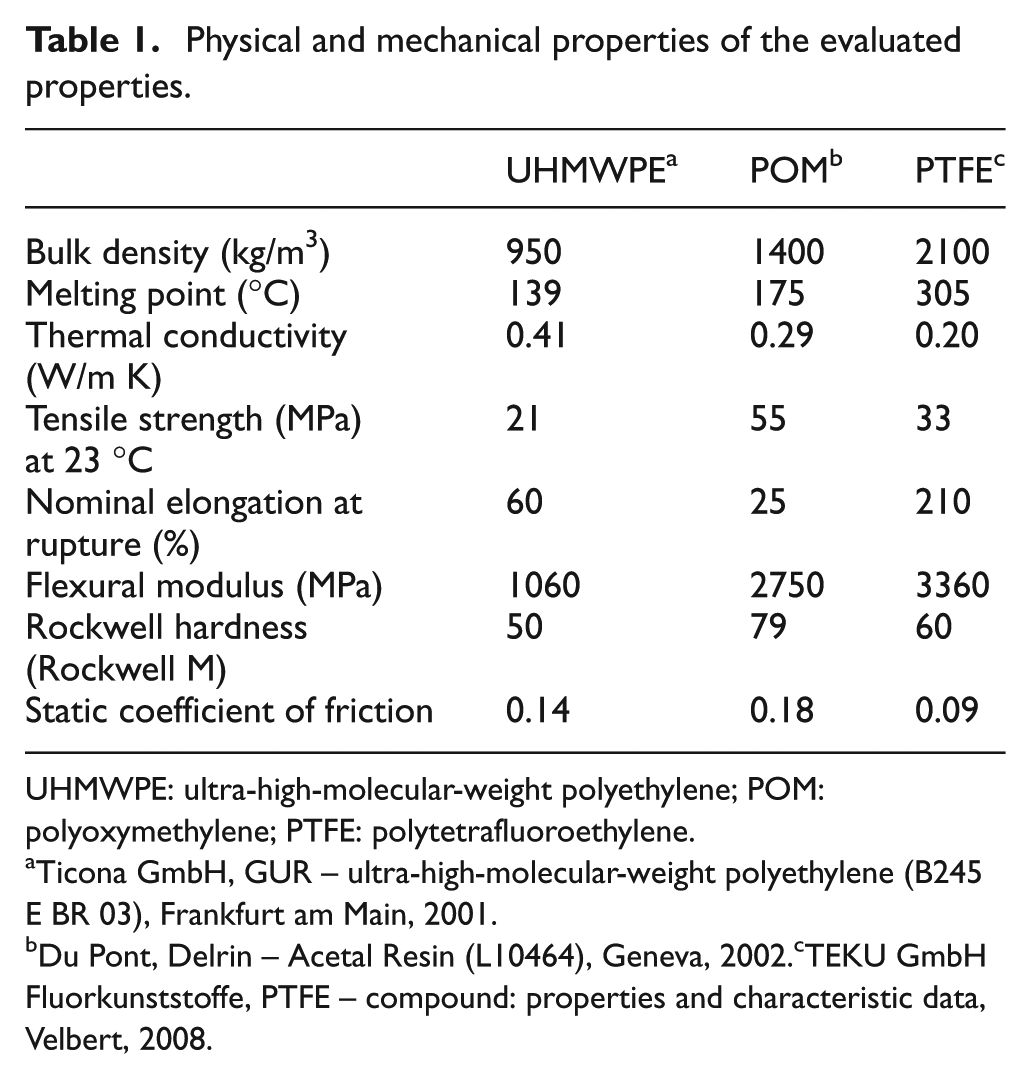
UHMWPE: ultra-high-molecular-weight polyethylene; POM: polyoxymethylene; PTFE: polytetrafluoroethylene.
Ticona GmbH, GUR – ultra-high-molecular-weight polyethylene (B245 E BR 03), Frankfurt am Main, 2001.
Du Pont, Delrin – Acetal Resin (L10464), Geneva, 2002. cTEKU GmbH Fluorkunststoffe, PTFE – compound: properties and characteristic data, Velbert, 2008.
UHMWPE
Polyethylene is characterized by a semi-crystalline polymer, made of crystalline regions and amorphous regions. The properties of polyethylene depend on the arrangement of the molecular chains. The number, the size and the type of molecular chains determine, in large part, the physical–mechanical properties such as density, stiffness, tensile strength, flexibility, hardness, brittleness, elongation, creep characteristics and melt viscosity. 11
The semi-crystalline polymers can be considered a blend of two phases, crystalline and amorphous, in which the crystalline phase is substantial in population. Such polymers (e.g. nylon, polypropylene and PTFE), in contrast to those which are essentially amorphous (e.g. polystyrene and polyvinylchloride), have a sufficiently ordered structure, so that substantial portions of their molecular chains are able to align closely to portions of adjoining molecular chains. 12
A beneficial consequence of polyethylene semi-crystalline nature is a very low glass transition temperature (Tg). A lower Tg endows a polymer with high toughness, impact absorption and elongation. UHMWPE (3–6 × 10⁶ g/mol) provides high wear and impact resistance. This material is immune to the electrochemical-based corrosion process that is induced by electrolytes such as salts, acids and bases. In addition, polyethylene parts are not vulnerable to biological attack, and its smooth, non-stick inner surface results in low friction and can be considered an advanced biomaterial used in surgery implants for hips, knees and so on.
Polyacetal or POM
Polyacetal or POM is a semi-crystalline thermoplastic material. The main raw materials are acetal copolymer and homopolymer. POM combines high stiffness with mechanical strength, besides revealing good elastic properties, high toughness, dimensional stability, excellent sliding friction characteristics and high hardness. Moreover, POM has good fatigue properties and machinability. The main applications of POM are construction machinery, vehicles, technology, transport and cargo handling, electrical, precision technology, domestic, food industry and medical appliances, where very high accuracy is needed in these machined parts. 13
Much research has focused on the material and tribological properties of POM. 13 However, only a limited number of investigations about the effects of the drilling parameters and the machining behaviour of such materials have been reported.
PTFE
PTFE is a synthetic fluoropolymer of tetrafluoroethylene that finds several applications. PTFE is most well known by the DuPont™ brand, namely, Teflon. PTFE tubes are made by plunger extrusion of suspension polymerized PTFE resin. Among all the existing plastics, extrusion PTFE has the best corrosion resistance and dielectricity. Often, PTFE can be used in insulating sleeve and corrosion-resistant tubes for different corrosive conditions and heat exchanger. In addition, this material can be considered an advanced biomaterial used in medical implants.
This polymer is hydrophobic, biologically inert and nonbiodegradable and also has low-friction characteristics and excellent ‘slipperiness’. The chemical inertness (stability) of PTFE is related to the strength of the fluorine–carbon bond. This is the reason in which nothing sticks to this polymer. Applications on medical, industrial and electronics are very common. As a medical material, PTFE has many uses, including arterial grafts, catheters, sutures and uses in reconstructive and cosmetic facial surgery. 14
PTFE is ideally suited for laboratory applications due to its resistance to strong acids and bases. It is also resistant to steam and low/high temperatures ranging from −200 °C (−390°F) to +300 °C (+570°F). The helical structure of the polymer chain, which is literally ‘sheathed’ by the F atoms, means that more chemically vulnerable carbon–carbon bonds are fully protected. 15
PTFE has been an important tribological material since the discovery of its low friction coefficient in 1940. 16 In addition to this property, PTFE is chemically inert and capable of withstanding elevated temperatures, making it useful for various extreme environments, including space applications in low earth orbit. 17 Despite these obvious benefits, PTFE has been excluded from many tribological applications due to its high wear rate under engineering sliding conditions.
Unfilled PTFE is known to suffer from subsurface crack propagation and subsequent delamination. Fillers of different shapes and sizes have been added to the PTFE matrix to reduce the wear by typically one or two orders of magnitude. 14
Experimental procedure
A full-factorial design was performed to identify the effect of the factors, feed rate (0.05 and 0.15 mm/rev), spindle speed (1000, 3000 and 5000 r/min), drill point angle (85°, 100° and 130°) and polymer type (UHMWPE, POM and PTFE) on the circularity error (Dm), average surface roughness (Ra) and thrust force (Ff) during the drilling process. The experimental levels were set based on the recommendations of Mastercam® CAD/CAM software. Table 2 exhibits the experimental factors and levels considered in this study, providing a full-factorial design of 3321, with a total of 54 conditions. Based on the surface roughness and the diameter error data, it is possible to control the finishing and the geometry error of machined components.
Experimental factors and levels (3321 = 54 conditions).
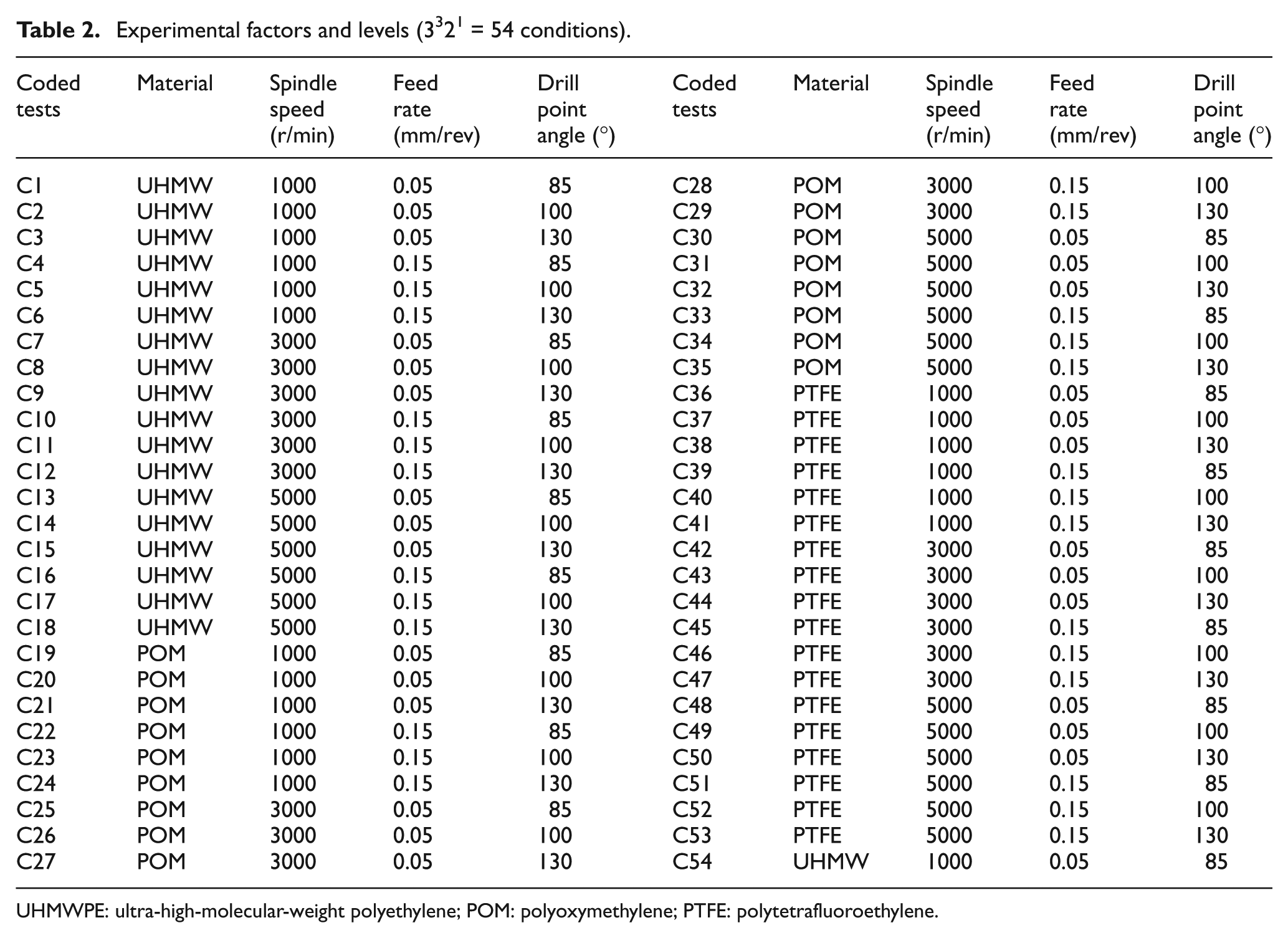
UHMWPE: ultra-high-molecular-weight polyethylene; POM: polyoxymethylene; PTFE: polytetrafluoroethylene.
Drilling experiments were performed on a machining centre with a spindle power of 7.5 kW and a maximum spindle speed of 6000 r/min. Figure 1 shows the experimental layout, in which an appropriate clamping system was designed to fix the samples to the machining centre. The framework highlighted in Figure 1 shows the drilling of a workpiece material with 90 mm in diameter and 20 mm in depth. High-speed steel twist drills grade A1141, with 10 mm diameter, 25° helix angle with different point angle values (85°, 100° and 130°) were ground and used as cutting tools (Figure 2). The drilling operation was replicated twice. The replicate consists of the repetition of the experimental condition in order to provide an estimate of experimental error against which the differences among treatments are assessed. The magnitude of this error is important in order to decide whether significant effect exists.
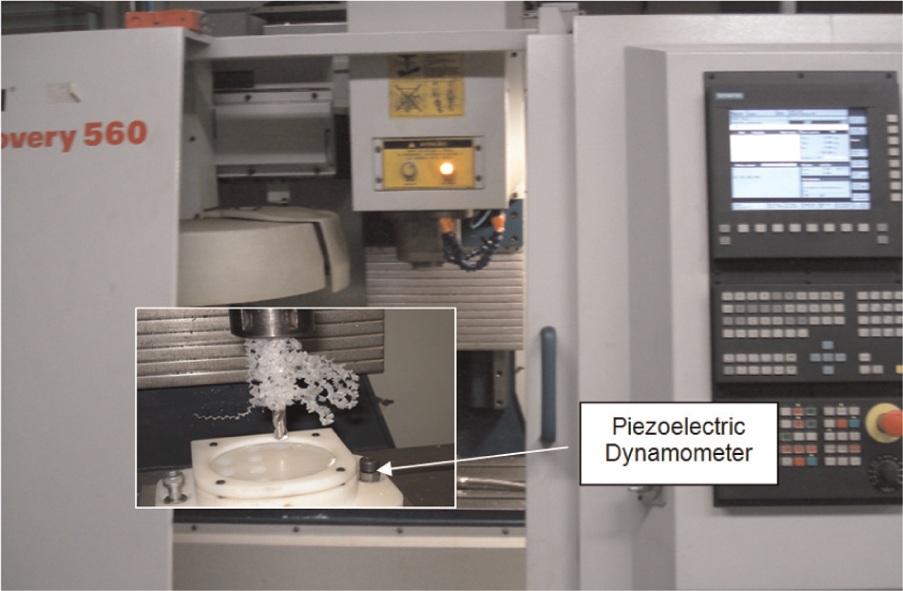
Experimental set-up.
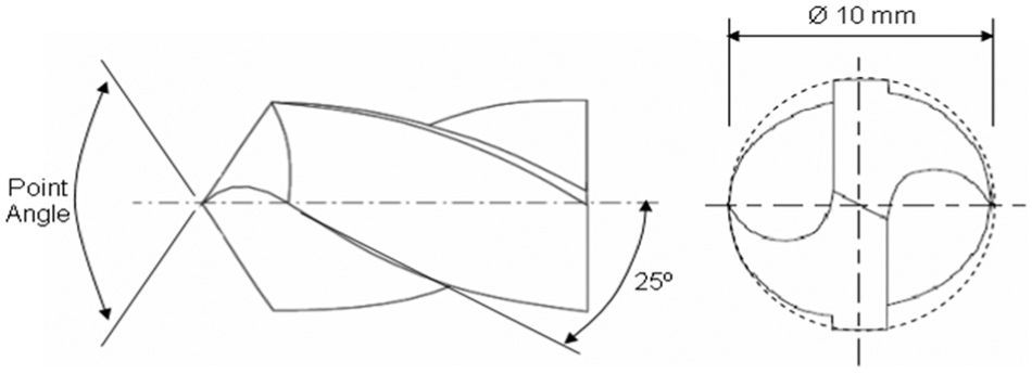
Illustration of the cutting tool.
The thrust force was measured using a Kistler piezoelectric dynamometer model 9257BA connected to a charge amplifier and a data acquisition board at 500 Hz. The roughness parameter was measured at three different angular positions inside the holes using a Mitutoyo Surftest 301 Surface Roughness Tester. The surface roughness tester was set as follows: cut-off at 0.8 mm, five sampling span, 4 mm evaluation length, 1000 points/span and a measuring range from 0.05 to 40 µm.
The hole diameter and circularity data were measured in the middle of the composite thickness using a coordinate measuring machine (CMM), Tesa Micro-hite 3D (see Figure 3(a)). Circularity is a two-dimensional geometric tolerance that evaluates how much a feature can deviate from a perfect circle. Seven points were measured, and the difference between the maximum and the minimum diameter of the circle was calculated.
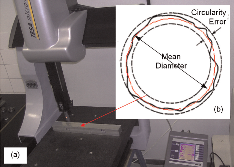
Roundness measurement: (a) coordinate measuring machine (Tesa Micro-hite 3D) and (b) measurement circle: mean diameter and circularity error.
Roundness is the condition where all points are located in a circle. To be considered round, the measured circle must fall within a specified tolerance zone formed by two concentric circles (circularity error). Figure 3(b) shows the deviation from the calculated circle for each measured points of the circle diameter (mean diameter and circularity error). The following set-up was used to measure the circle diameter using CMM:
Unidirectional repeatability: 0.75 µm;
Calibration and error compensation: 0.001 mm;
Three-dimensional probe: ruby ball ∅ 2 mm;
Number of points for circle: 07.
Results
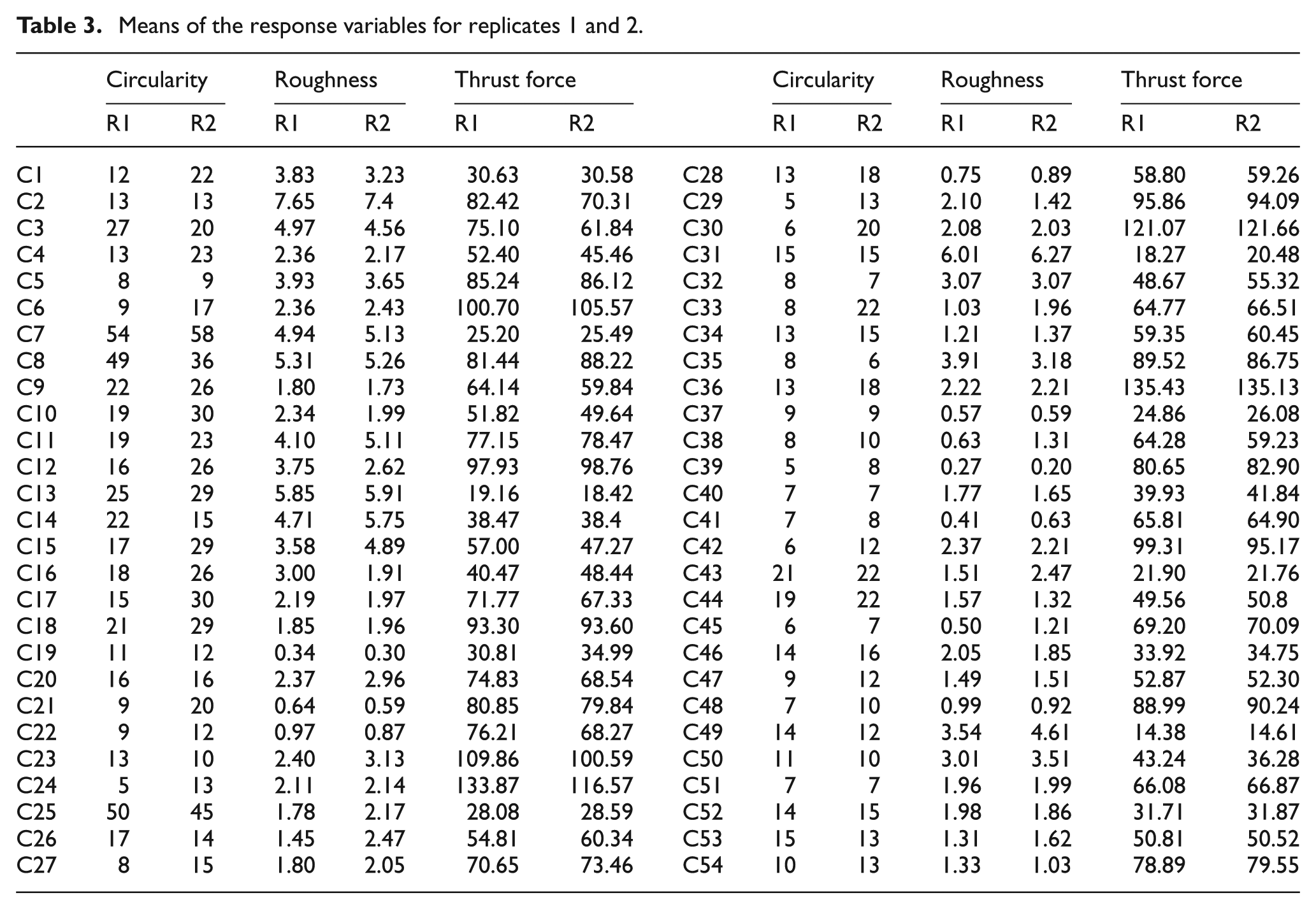
Table 3 shows the means of the response variables for all experimental conditions (C1–C54) for replicates 1 and 2, which were used to perform the analysis of variance (ANOVA).
Means of the response variables for replicates 1 and 2.
The ANOVA was performed by the statistical software Minitab®, version 14. Table 4 shows the results from the ANOVA related to the mean values of the response variables. The p values indicate which of the effects in the system are statistically significant, based on the examination of the experimental data from replicates 1 and 2. If the p value is less than or equal to 0.05, the effect is considered significant. An α level of 0.05 is the level of significance, which implies a 95% probability of the effect being significant. 18 The results are presented via ‘main effect’ and ‘interaction’ plots. These graphical plots cannot be considered typical ‘scatter’ plots, but they rather illustrate the statistical analysis and provide a graphical variation of the significant effects. 19 The main effect of a factor must be individually interpreted only when there is no evidence of interaction with other factors. When one or more interaction effects of superior order are significant, the factors that interact might be mutually considered. 19
Analyses of variance (ANOVA) – Minitab®, version 14.
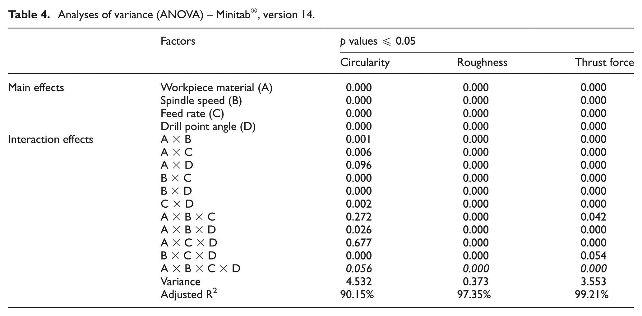
The italicized values in Table 4 correspond to the significant effects, which will be presented via interaction plots. The experimental factors were designated by the following letters: ‘A’ stands for workpiece material, ‘B’ for spindle speed, ‘C’ for feed rate and ‘D’ for the drill point angle.
The value of ‘adjusted R2’ shown in the ANOVA indicates how well the model predicts responses for new observations. Larger values of R2 (R2 > 0.90) suggest models of greater predictive ability. 19 Table 4 shows the values of adjusted R2 for each response being superior to 90%, demonstrating that the quality of adjustment of the models has been satisfactory.
Circularity error
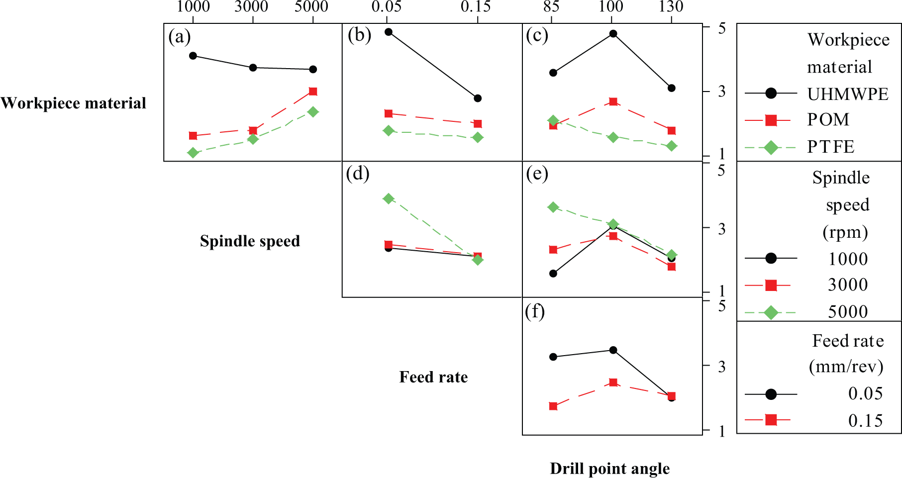
The circularity error data varied from 5 to 58 µm. Figure 4 shows the interaction effect plot of the factors ‘workpiece material, spindle speed, feed rate and drill point angle’ on the circularity error response.
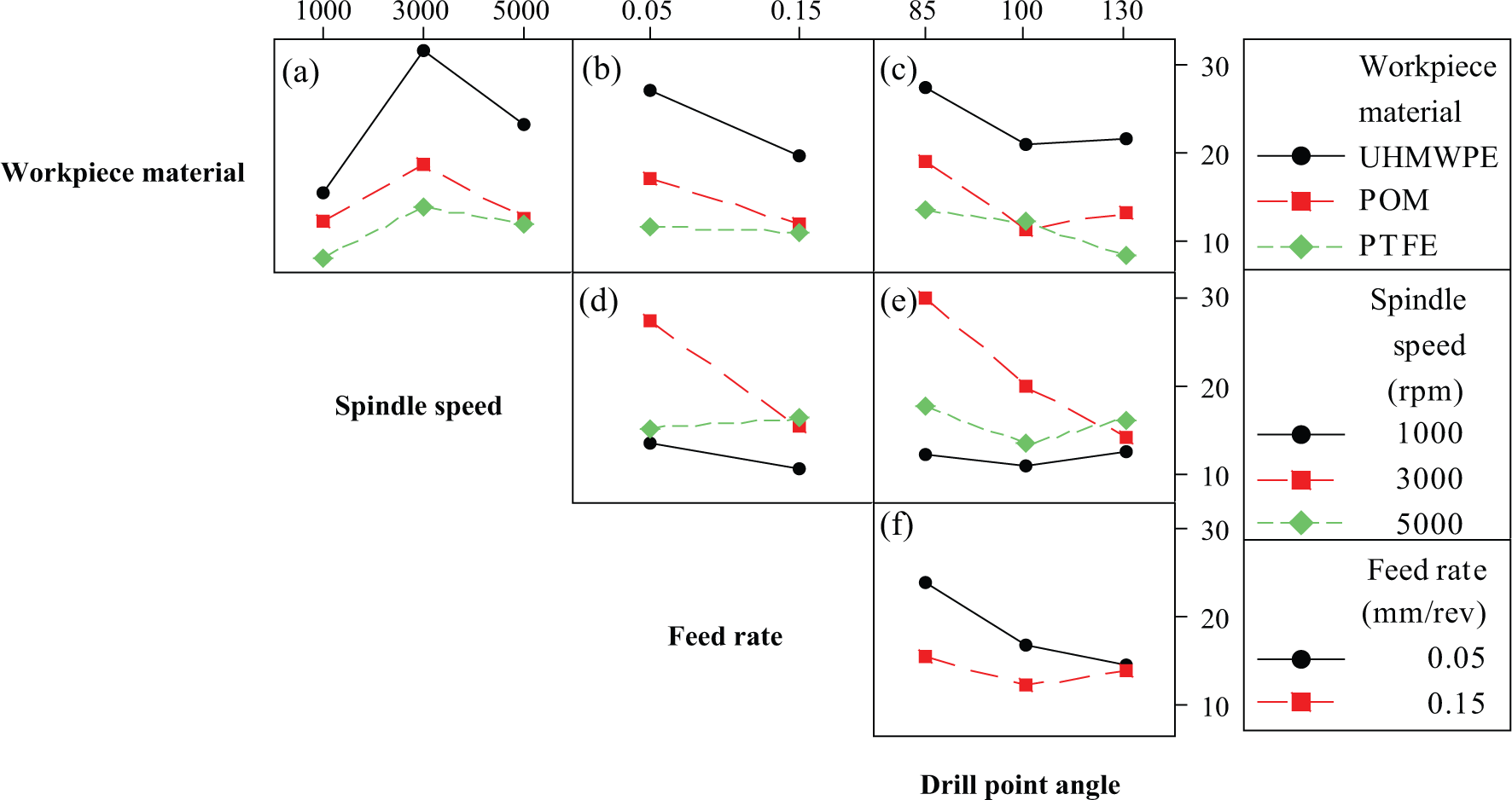
Interaction effect plot of fourth order for the circularity error response.
Figure 4(a)–(c) reveals that the lowest circularity error was achieved when the PTFE (Teflon) was considered. The increase of interface temperature can explain this behaviour; since PTFE exhibits a higher melting point temperature and stiffness (see Table 1). The lower spindle speed (Figure 4(a)) and feed rate (Figure 4(b)) levels and the higher drill point angle level (Figure 4(c)) led to reduce the circularity error for all polymers.
Two opposite effects were observed when the spindle speed was increased. The first one was the increase of cutting temperature, which consequently decreases the compressive stress on the primary shear zone. The second one can be attributed to the reduction of contact time, which explains the lower circularity error reached at 5000 r/min (Figure 4(a)) in comparison to 3000 r/min.
A significant reduction on the circularity error was observed by varying the feed rate (Figure 4(d)) and drill point angle (Figure 4(e)), mainly when the spindle speed was set at 3000 r/min. However, a lower circularity error was achieved when the spindle speed was set at 1000 r/min using a feed rate of 0.15 mm/rev (Figure 4(d)) and a drill point angle of 100° (Figure 4(e) and (f)). The reduction of the circularity error response by the increasing of feed rate (Figure 4(d)) and drill point angle (Figure 4(f)) levels can be attributed to the reduction of the cutting temperature and contact length (contact time), respectively.
Surface roughness
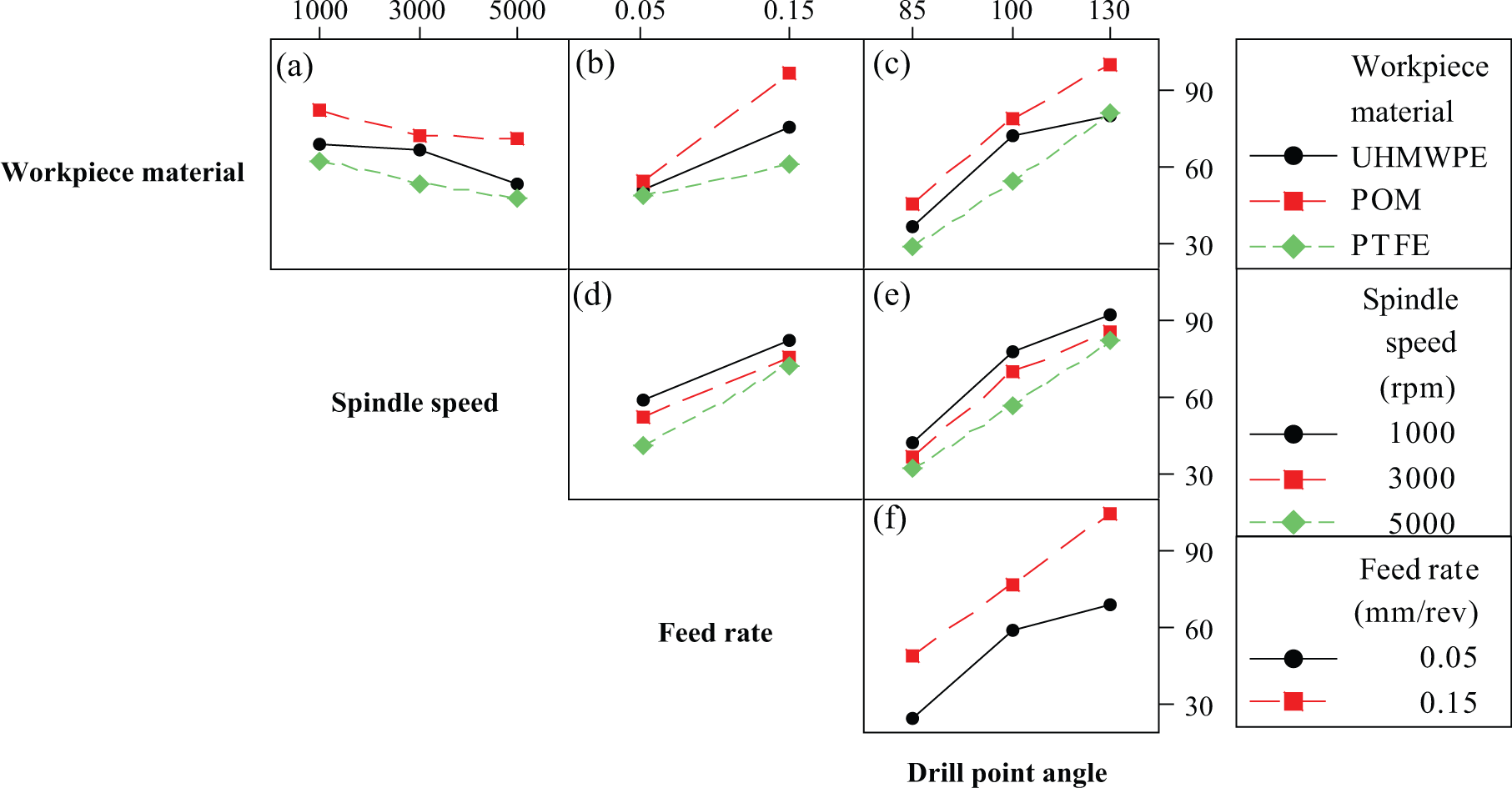
The surface roughness data varied from 0.20 to 7.65 µm. The ANOVA revealed that a fourth-order effect was significant, exhibiting a p value of 0.000, italicized in Table 4. Figure 5 shows the interaction effect plot for the surface roughness (Ra).
Interaction effect plot of fourth order for the surface roughness response.
In the conventional metal machining, it can be stated that the spindle speed increase provides a thrust force reduction, consequently leading to a better surface finishing. This behaviour was not clearly observed for polymeric materials since high roughness level was achieved when high spindle speed was set (see Figure 5(a)). This effect can be attributed to the increase of the cutting temperature, providing further deterioration on the material’s surface.
The physical and mechanical properties of UHMWPE are lower than the POM and PTFE polymers (bulk density, melting point and stiffness; see Table 1). The thermal conductivity is, however, much higher, making the material capable of transferring heat faster and at high larger depth during the drilling process, and consequently affecting the surface roughness. Figure 5(a)–(c) shows a significant difference in the roughness response between ‘UHMWPE’ and ‘POM–PTFE’ for all cutting parameters.
Engineering polymeric materials do not have low melting points. Nevertheless, thermal degradation occurs through a depolymerization or ‘unzipping’ mechanism, leading to a virtual or complete breakdown of the polymer chains. The result above shows that the PTFE exhibited the best performance during the drilling process. This result implies that the cutting temperature level was too high for the UHMWPE and POM polymers.
The roughness data were affected by the spindle speed variation mainly when the feed rate and drill point angle were set at the lower level, as shown in Figure 5(d) and (e), respectively. Figure 5(f) shows the interaction of spindle speed and drill point angle factors. It is noted that there is one more optimum set-up, which minimizes the roughness response, which consists of a low feed rate at 0.05 mm/rev and a high drill point angle at 130°. Alternatively, it is possible to use a high feed rate at 0.15 mm/rev and a low drill point angle at 85°.
Thrust force
The thrust force data varied from 14.38 to 135 N. Based on the ANOVA (Table 1), Figure 6 presents the interaction effect plot for the thrust force response.
Interaction effect plot of fourth order for the thrust force response.
The lower thrust force levels were measured for PTFE work material, and subsequently the UHMWPE and POM, as shown in Figure 6(a)–(c). The cutting set-up that minimizes the thrust force was set as follows: spindle speed at high level (Figure 6(d) and (e)), feed rate at low level (Figure 6(d) and (f)) and drill point angle at low level (Figure 6(e) and (f)).
The increase of spindle speed reduces the thrust force due to the heat transfer, which affects the ductility of the material. This effect hinders the chip output, which leads to the increase of the thrust force when polymer materials are drilled. The thrust force rises when the feed rate is increased due to the amount of shared work material. The drill point angle is related to the tool contact area, which means that high drill point angles provide lower contact area, resulting in lower cutting temperatures.
Topographic analysis
A scanning electron microscope (SEM; Hitachi T-3000) was used to observe the topography of the drilled holes in backscattered electron mode detector with an accelerating voltage of 15 kV. The nomenclatures S1–S3 correspond to the experimental set-up as follows:
S1: 0.05 mm/rev, 1000 r/min;
S2: 0.05 mm/rev, 5000 r/min;
S3: 0.15 mm/rev, 5000 r/min.
Figure 7(a)–(c) shows the backscattered electron images of the drilled hole topography for UHMWPE, POM and PTFE, respectively, at 150× of magnification. As expected, Figure 7 reveals a reduction of the surface roughness based on the following material’s order, UHMWPE, POM and PTFE, since the stiffness and the melting point of these materials are considerably increased, respectively (see Table 1).
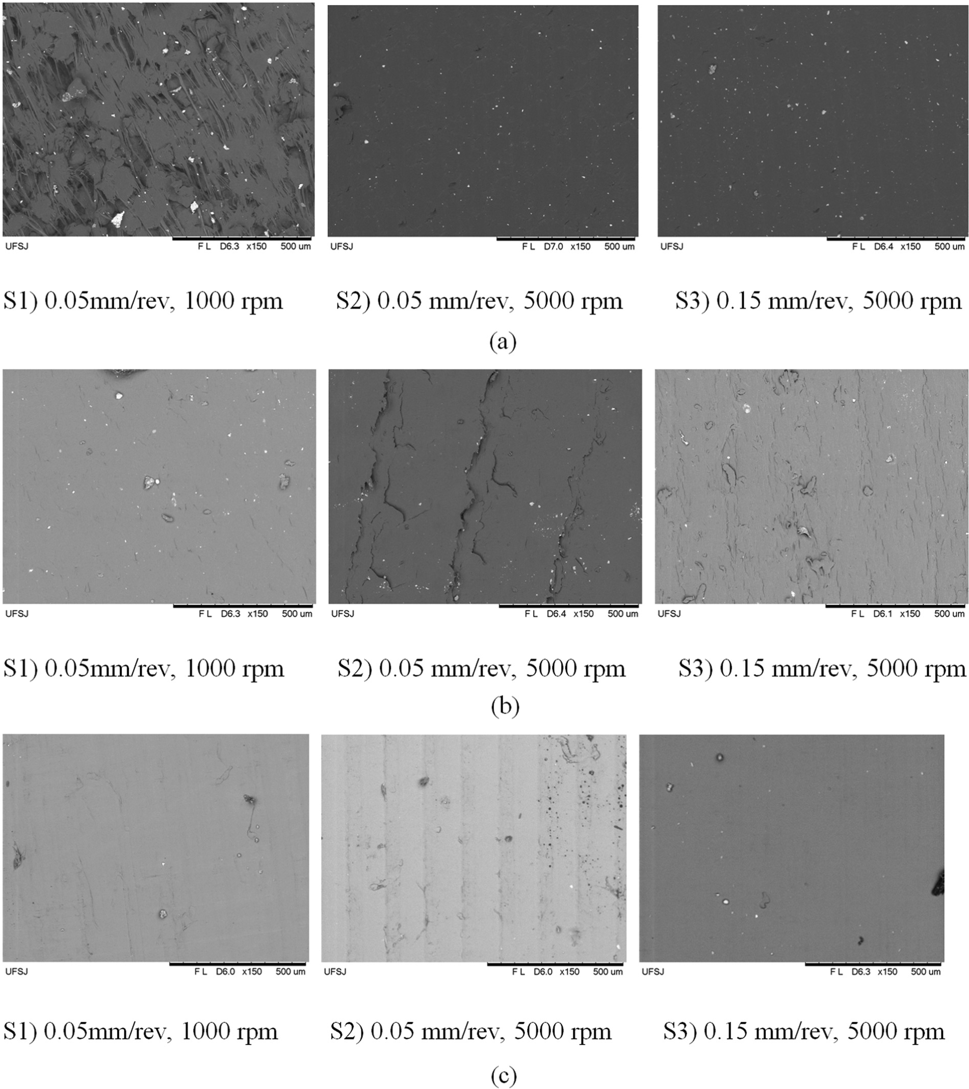
Backscattered electron images at 150× of magnification of the drilled holes for composites: (a) UHMWPE, (b) POM and (c) PTFE.
A significant difference between S1 and S2 for POM (Figure 7(b)) and PTFE (Figure 7(c)) was identified, which is in accordance with the results presented in Figure 5(a). The surface roughness of UHMWPE composites was reduced when the spindle speed increased from 1000 to 5000 r/min (Figure 5(a)). This behaviour is in agreement with the topography presented in Figure 7(a) (S1 and S2). The surface finishing of UHMWPE sample at low feed rate and spindle speed levels (S1) is quite rough, indicating that this machining set-up is not adequate for this material. In opposite, the quality of surface finishing for POM sample is worse, which is in agreement with the roughness measurement presented in Figure 5(a).
At 5000 r/min, the surface finishing is improved when the feed rate rises from 0.05 mm/rev (S2) to 0.15 mm/rev (S3), as observed in Figure 7. This behaviour was also revealed by the interaction effect plot, as shown in Figure 5(d).
Conclusion
The work described investigates the effect of drilling parameters and different engineering plastics on the quality of the hole and the drilling thrust force. The main conclusions from the full-factorial design analysis of 3321 are as follows:
The circularity error can be minimized when the cutting parameter levels are set as follows: feed rate at 0.15 mm/rev (high), drill point angle at 130° (high) and spindle speed at 1000 r/min (low).
The spindle speed set at 1000 r/min minimizes the roughness values. However, the feed rate and drill point angle can be combined to achieve a better roughness (e.g. low feed rate (0.05 mm/rev) and high drill point angle (130°) or high feed rate (0.15 mm/rev) and low drill point angle (85°)).
The cutting set-up, which minimizes the thrust force, is spindle speed at high level (5000 r/min), feed rate at low level (0.05 mm/rev) and drill point angle at low level (85°).
The thrust force values obtained for the same feed rate can be assigned to differences in drill geometry and machining material.
The UHMWPE polymer provided larger values of circularity, roughness, and consequently lower thrust forces. On the other hand, the PTFE (Teflon) revealed an opposite behaviour, since it exhibits higher bulk density and stiffness and lower thermal conductivity, which affects the chip output mechanism and the hole accuracy.
The microstructural analysis revealed a rough surface finishing for the UHMWPE samples when the machining set-up was set at low feed rate and spindle speed.
Footnotes
Declaration of conflicting interests
The authors declare that there is no conflict of interest.
Funding
This research received no specific grant from any funding agency in the public, commercial or not-for-profit sectors.