
Abstract
Thanks to its superior mechanical and physical properties, silicon carbide is a promising mold material in glass molding of micro-structured optical elements. However, the high micro-structured surface quality can be hardly generated by means of conventional abrasive polishing because of the high hardness of silicon carbide. In this article, the ultrasonic vibration was introduced to assist abrasive polishing with an aim to improve the cylindrical groove arrays’ surface quality and also to increase the polishing efficiency. First, the comparison experiments between abrasive polishing and ultrasonic vibration–assisted polishing were conducted, and then, the factors affecting ultrasonic vibration–assisted polishing performance were investigated. The experimental results indicate that through conventional abrasive polishing, the surface roughness of silicon carbide cylindrical groove arrays decreases to 25.5 nm from the precision ground surface roughness (Ra) of 115.6 nm, while through ultrasonic vibration–assisted polishing, the surface roughness decreases to 8.6 nm with a factor of three times improvement. Furthermore, a 35-kHz vibration frequency corresponds to a smaller surface roughness than a 25-kHz vibration frequency under identical processing parameters. In the vibration amplitude range from 1.0 to 2.5 µm, the surface roughness accordingly decreases linearly, while in the range of 2.5–4.0 µm, ultrasonic vibration presents no assistance in improving the surface quality.
Keywords
Introduction
Micro-structured optical components made of glasses are promisingly replicated by glass molding with mold material such as silicon carbide (SiC) because of its high wear resistance, high temperature resistance, and high thermal conductivity.1,2 However, high-quality micro-structured surface on SiC molds is quite difficult to obtain directly by ultraprecision grinding attributed to those superb material property,3–5 thus these micro-structured surfaces on SiC have to be finished by lapping or polishing after grinding. While conventional abrasive polishing (AP) is usually used for soft materials such as mold steels, which is very difficult for SiC because of the high hardness and high strength.6,7 In addition, AP is commonly used for continuous surfaces in which random movement is usually applied, while there is no additional random movement applied to the discontinuous micro-structures which may affect the uniformity of material removal. 8 Furthermore, there will be conglomeration phenomenon presented for nanometer-sized abrasive grains, which may also affect the surface quality.
In consideration of improving the micro-structured surface quality and form accuracy, ultrasonic vibration–assisted polishing (UVAP) is proposed in this article. In contrast to AP, UVAP has its unique advantages, such as (a) avoiding the conglomeration phenomenon of the abrasive grains,9,10 (b) decreasing the frictional force between SiC and the abrasive grains or polishing wheel,11–13 (c) obtaining better surface quality,14,15 and (d) changing the polishing trajectory, which makes material removal more uniform.
In this article, an ultrasonic vibration table integrated in the ultraprecision planar grinder was used to introduce the ultrasonic vibration in the polishing process of cylindrical groove arrays. The surface quality obtained by AP and UVAP was compared under identical polishing parameters. Then, the effects of vibration frequency, vibration amplitude, workpiece feed speed, and polishing time on surface roughness were investigated. The surface roughness was evaluated by a contact probe profilometer, while a scanning electron microscopy (SEM) was used to assess the surface morphology generated by AP and UVAP.
The UVAP principle for machining the cylindrical groove arrays
As shown in Figure 1, the cylindrical groove arrays were pre-machined by precision grinding using micro-structured diamond wheel. However, the ground surfaces have to be finished by subsequent UVAP to improve the surface quality because the ground surface roughness cannot meet the requirement.
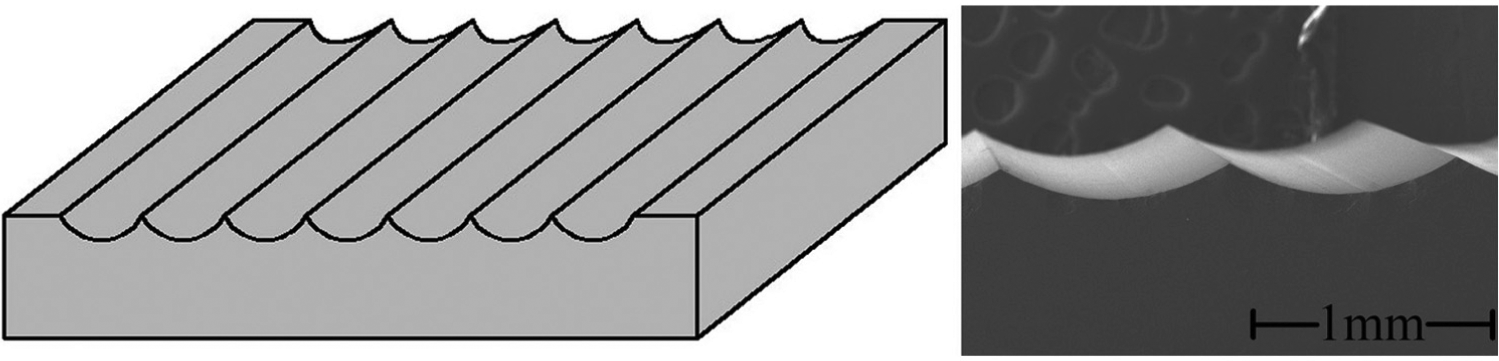
Sketch map and SEM image of cylindrical groove arrays.
The UVAP principle diagram of machining micro-structures is shown in Figure 2(a). The arc section of the polishing wheel work zone shares the same profile as that of the cylindrical groove on SiC. In the polishing process, the polishing wheel rotates at a certain speed, while the workpiece (SiC) moves at a certain tangential feed speed. In addition, two kinds of vibration frequencies 25 and 35 kHz can be chosen, the vibration amplitude can also be adjusted accordingly, and the vibration direction parallels the feed direction of the SiC workpiece.
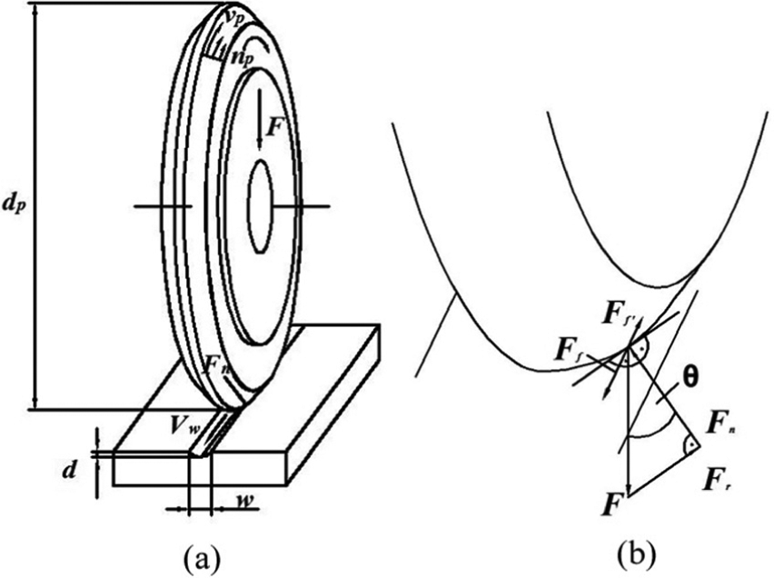
Schematic diagram of (a) polishing motion and (b) interaction forces during UVAP process.
Figure 2(b) shows the force diagram of the arc-shaped contact surface in between the wheel and workpiece. During UVAP process, the polishing wheel is pressed onto the cylindrical groove with a vertical force F, which causes a normal force Fn and a radial force Fr because of the arc-shaped interaction surface. Furthermore, when the polishing wheel and SiC workpiece move relatively, the friction force Ff will be accordingly produced on the arc interaction surface.
The experimental setup of UVAP
The polishing experiments were performed on the same precision grinder (MUGK7120X5 horizontal spindle surface grinder) after grinding in order to avoid repositioning error of workpiece. As shown in Figure 3, the SiC workpiece is fixed on the ultrasonic vibration tool head with bonding glue, and the force transducer is installed beneath to measure the three-dimensional forces acting on the micro-structured surfaces. The polishing process is observed online by an optical microscope.
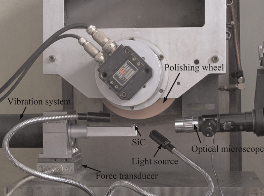
The experimental setup of UVAP.
The ultrasonic vibration device
The ultrasonic vibration systems with 25 and 35 kHz frequencies are mainly composed of ultrasonic generator, ultrasonic transducer, the ultrasonic horn, and the tool head, as shown in Figure 4. The ultrasonic vibration system can be mounted on the force transducer, and the cantilever of tool head meets the stiffness requirement via calculation.
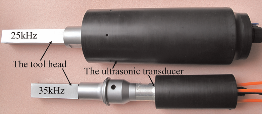
The ultrasonic vibration systems.
The truing for polishing wheel
A nanometer grain-sized cerium oxide polishing wheel was applied in this experiment. The polishing wheel is porous, which can contain more abrasives of the polishing liquid as shown in Figure 5. In addition, the wheel’s high strength can maintain the micro-structured shape, while its toughness can embed the abrasive grains to assure that the polishing effect works. The micro-structured profile in the polishing wheel circumference surface can be trued by precision turning on machine with a diamond tool to minimize the run-out error and meanwhile to generate the accurate micro-structured shape. Before and after diamond turning, the cross-sectioned profile of polishing wheel is measured by a laser displacement measuring system, as shown in Figure 6.
The SEM photograph of the polishing wheel surface.
The comparison of polishing wheel’s cross-sectioned profile: (a) before truing and (b) after truing.
The pre-adjustment of UVAP
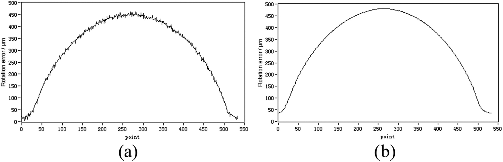
Prior to UVAP, the relative position adjustment between the polishing wheel and the cylindrical groove on the workpiece is a key prerequisite to ensure the micro-structure’s profile accuracy. Therefore, an accurate adjustment method is proposed in which the polishing wheel above a cylindrical groove can be simultaneously observed and controlled by the optical microscope and the force transducer correspondingly. As illustrated in Figures 7 and 8, the optical microscope is used for the preliminary observation, and then, the force transducer is used for further precise adjustment. When the changes in the axial force between SiC and polishing wheel during the polishing process approach zero, the adjustment is finished.
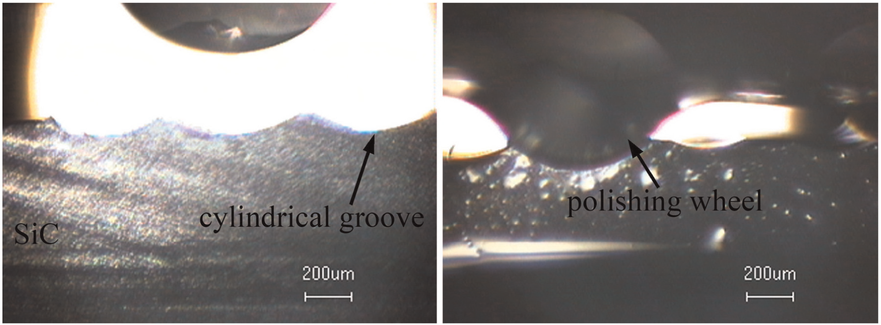
The adjustment method by the optical microscope.
The measured axial force for adjustment: (a) before adjustment and (b) after adjustment.
Polishing parameters
The cylindrical groove arrays were ground on the precision surface grinder before UVAP with designed individual groove’s width of 0.8 mm, depth of 90 µm, and radius of 1.0 mm; the surface roughness (Ra) of the ground cylindrical groove is 115.6 nm. An overview of the UVAP conditions is given in Table 1.
Experimental parameters of UVAP.
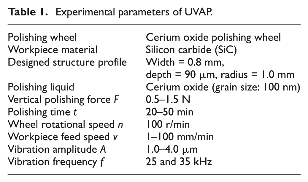
Since the chemical reaction can occur between SiC and cerium oxide polishing liquid, which is proved by the generation of the soft layer of silica oxide detected by a X-ray diffractometer (XRD) through the preliminary experiments, a water-based cerium oxide slurry with a grain size of 100 nm was used for all experiments with an aim to decrease the surface roughness. The polishing wheel rotational speed n is 100 r/min, the workpiece feed speed v is varied in the range of 1–100 mm/min, the polishing time t is varied in the range of 20–50 min, and the vertical polishing forces F are in the range of 0.5–1.5 N. There are two kinds of vibration frequency f 25 and 35 kHz applied with the vibration amplitude A varying in the range of 1.0–4.0 µm.
Experimental results and discussion
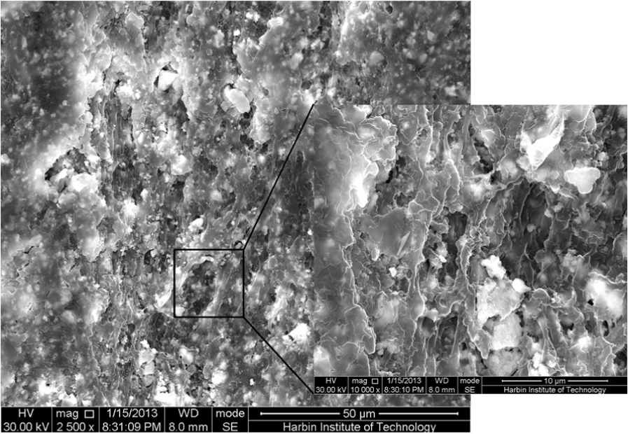
The surface roughness and profile accuracy of the cylindrical groove arrays machined by AP and UVAP are shown in Figures 9 and 10, respectively. When corresponding to f of 25 kHz, A of 1.5 µm, F of 1.5 N, t of 50 min, and v of 5 mm/min, the surface roughness after AP is decreased to 25.5 nm, while it can be greatly improved to 8.6 nm by introducing ultrasonic vibration assistance under the identical polishing parameters with AP. Furthermore, AP generates a profile accuracy of the cylindrical groove of 2.7844 µm, while through UVAP the profile accuracy decreases to 0.8925 µm; the radius of 1.135 mm can be obtained by AP, while the UVAP can generate a radius of 1.0221 mm more close to a designed value of 1.0 mm. According to the SEM photographs shown in Figure 11, the better surface quality can be generated through UVAP than AP in terms of the diminished scratches and grinding marks, owing to the different kinematics and material removal mode in between.
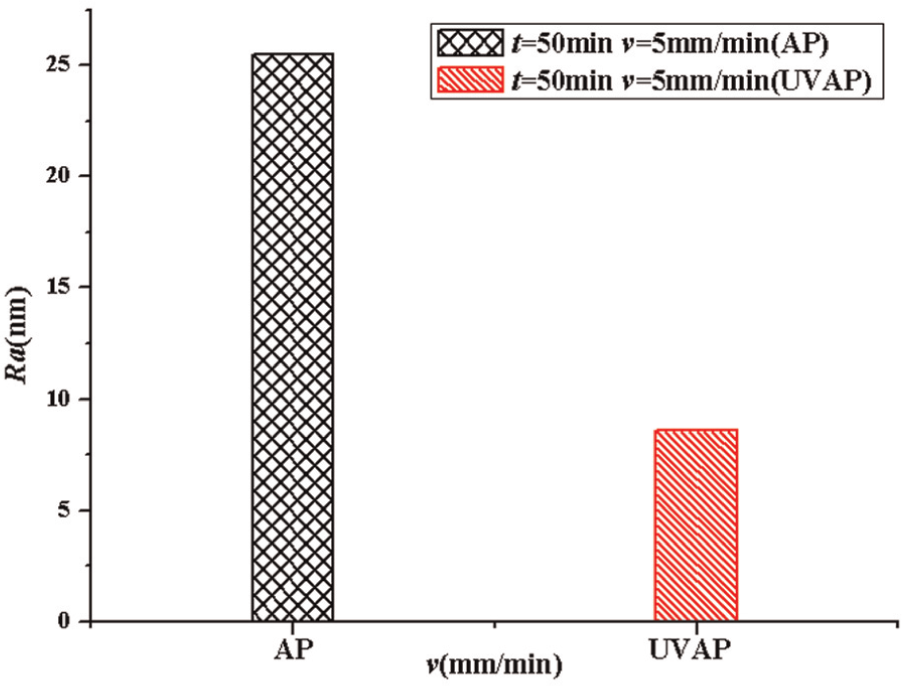
Surface roughness contrasts after AP and UVAP.
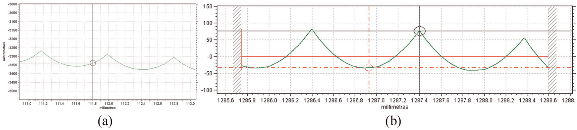
Profile of cylindrical groove arrays on SiC: (a) AP and (b) UVAP.
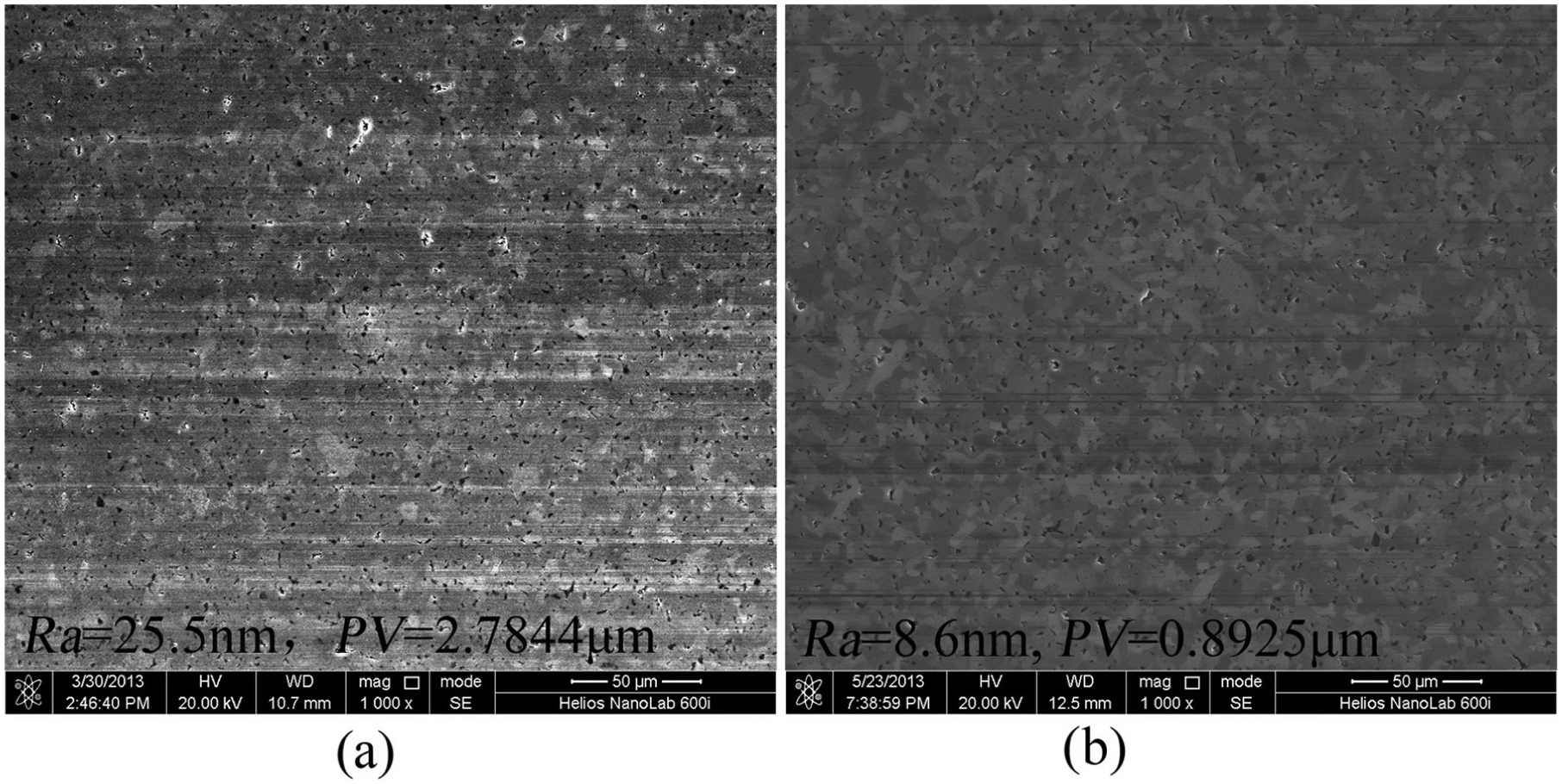
SEM photographs of micro-structured surfaces: (a) AP and (b) UVAP.
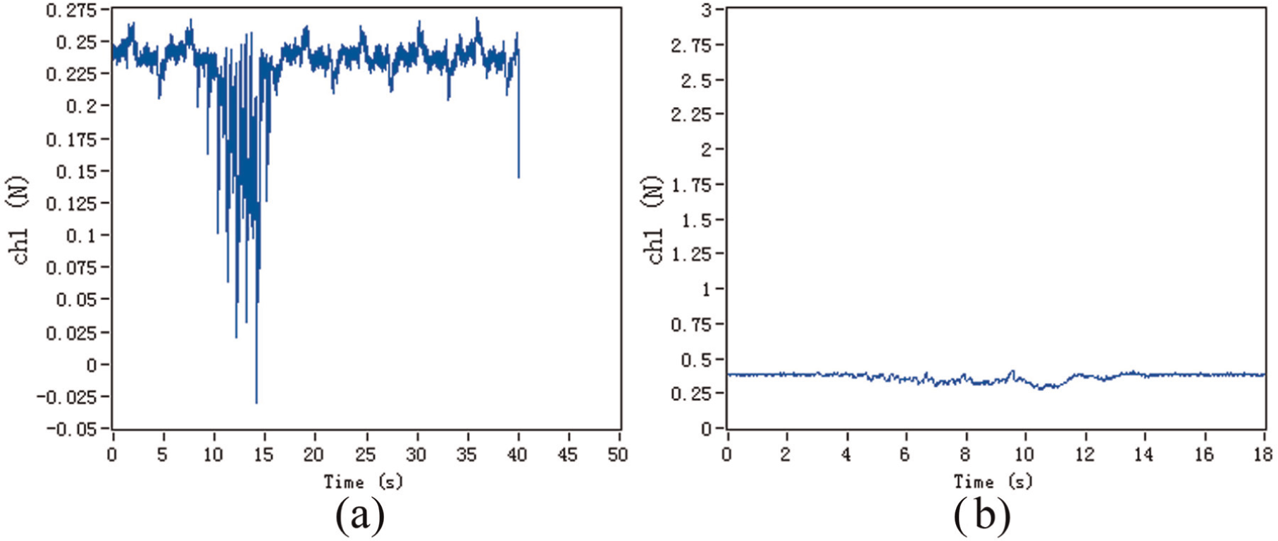
The above conclusion can be further explained by the measured friction force Ff as shown in Figure 12, indicating that the application of ultrasonic vibration can result in a reduction of Ff during the polishing process. Because the size of the abrasive grains is in the nanometer range, it is easy to produce conglomeration phenomenon to form a larger size of the abrasive, which will be embedded in the polishing wheel generating plough effects on the micro-grooved surface and then forming scratches. Once the ultrasonic vibration is introduced, the friction force will be accordingly decreased indicating that the cavitation phenomenon can be produced to thereafter weaken the conglomeration of the abrasives, making them distribute more uniformly. This is helpful to remove the material more uniformly resulting in a decrease in the polished surface roughness. In addition, the cavitation phenomenon also can reduce the amount of the embedded abrasives, meaning the two-body abrasion will be converted into the three-body abrasion, and also can be beneficial in prohibiting the production of scratches that are produced by two-body abrasions when the ultrasonic vibration is not applied.
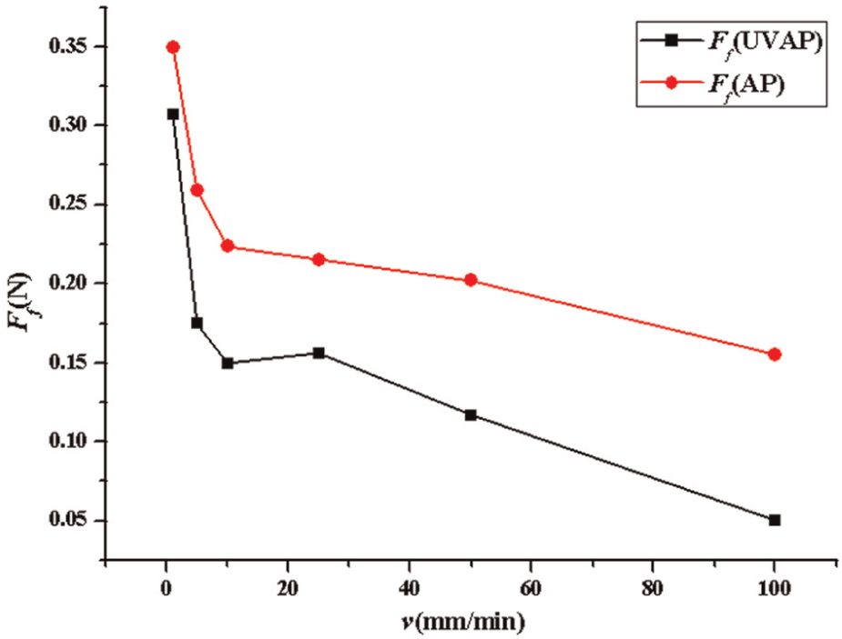
The comparison of the friction forces under AP and UVAP.
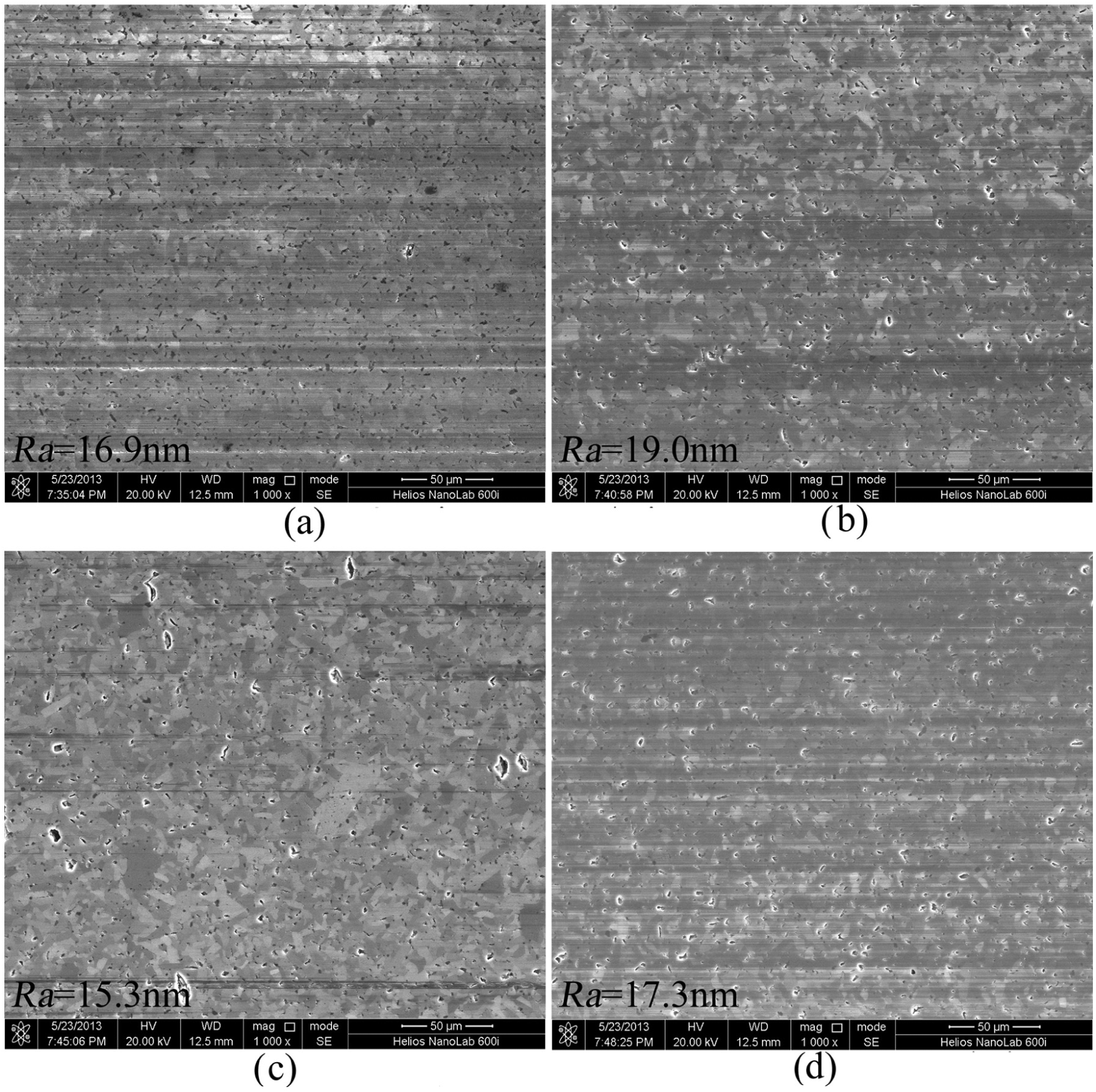
The surface roughnesses as a function of vibration amplitude A and frequency f at F = 0.5 N, t = 35 min, and v = 5 mm/min are shown in Figure 13. As A increases in the range of 1.0–4.0 µm, there is a threshold at A = 2.5 µm. When A falls in the threshold smaller than 2.5 µm, the polished surface quality can be improved via UVAP. However, there are no additional benefits in improving the surface quality when A is beyond the threshold of 2.5 till 4 µm. At f = 25 kHz, the surface roughness is improved from 25.1 to 13.7 nm with increased amplitude from 1.5 to 2.5 µm, while at f = 35 kHz it is improved from 17.3 to 11.1 nm with the same increased range of A, indicating that a better surface quality of the micro-groove can be produced corresponding to a 35-kHz vibration frequency than to a 25-kHz vibration frequency. The surface morphology formed by different f and A is shown in Figure 14. The SEM photographs show that the scratches generated by micro-ploughing on the polished surface decrease when A increases in the range of 1.0–2.5 µm under both vibration frequencies of 25 and 35 kHz. With regard to vibration frequency f, 35 kHz is able to generate a superior surface quality featuring fewer scratches generated (see Figure 14(c) and (d)) than with 25 kHz (see Figure 14(a) and (b)), resulting in a decreased surface roughness (Ra) corresponding to the measured results as shown in Figure 13.
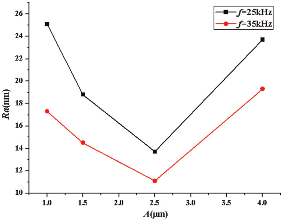
The effect of A on surface roughness (Ra) at different f.
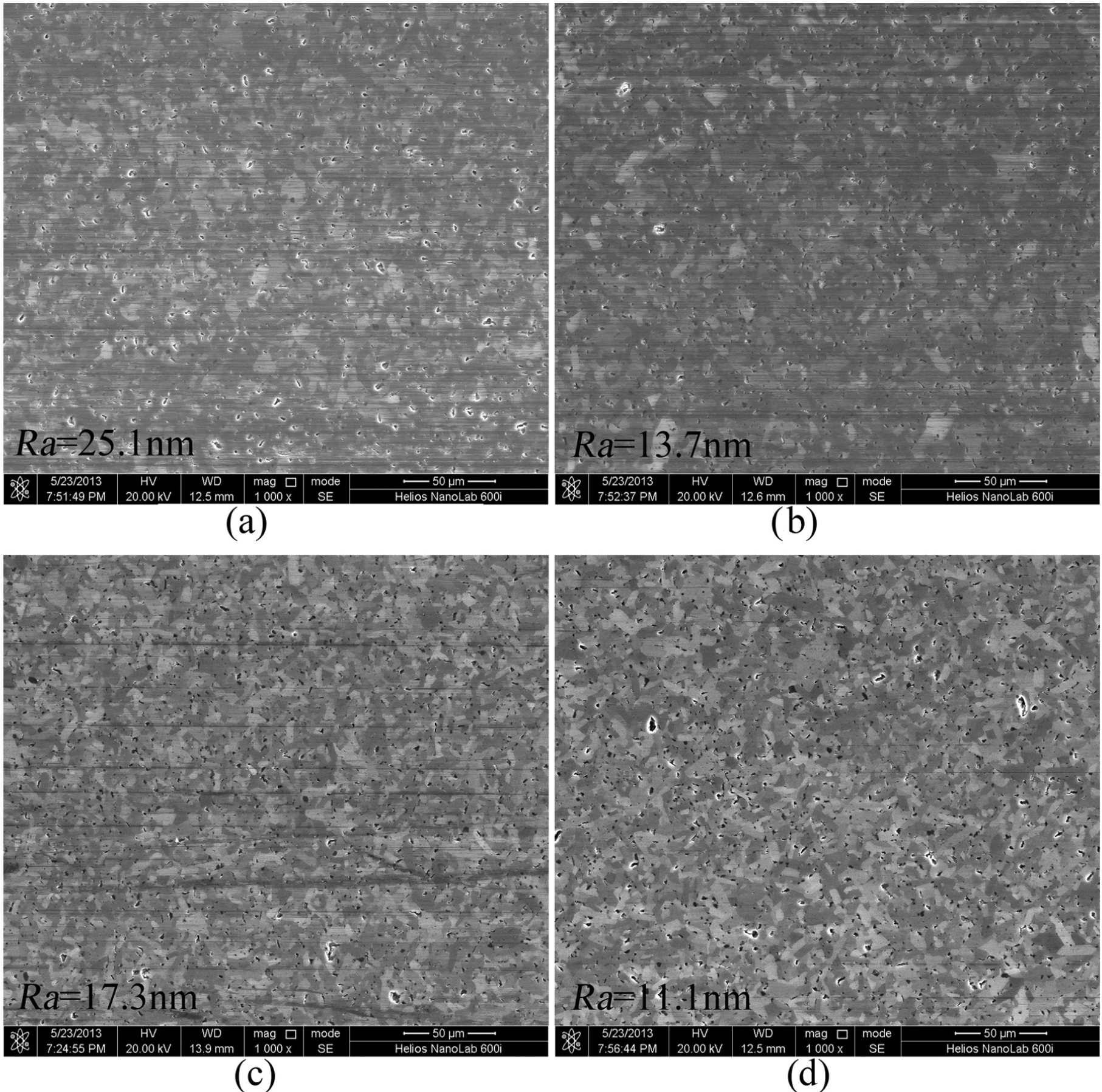
The SEM photographs of polished surface at different f and A: (a) f = 25 kHz, A = 1.0 µm; (b) f = 25 kHz, A = 2.5 µm; (c) f = 35 kHz, A = 1.0 µm; and (d) f = 35 kHz, A = 2.5 µm.
The effects of workpiece speed v and polishing time t on the cylindrical grooved surface roughness at f = 25 kHz, A = 1.5 µm, and F = 0.5 N are shown in Figure 15. Figure 16 shows the cylindrical grooved surface morphology measured by SEM through UVAP. The surface quality deteriorates with the increased v from 1 to 100 mm/min featuring more scratches generated on the polished surface (refer Figure 15). This can be explained that as the workpiece speed v increases, the more abrasive grains will be embedded into the polishing wheel acting like fixed abrasives which can generate more scratches. When t is 20 min, the surface roughness is the largest, while later on as t increases the surface roughness decreases accordingly. However, when the polishing time runs longer than 35 min, the resulting surface quality shows no further improvement compared to a polishing time of 50 min (refer Figure 15).
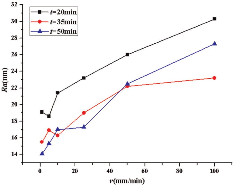
The effect of v on surface roughness (Ra) at different t.
The SEM photographs of polished surface quality through UVAP: (a) t = 35 min, v = 5 mm/min; (b) t = 35 min, v = 25 mm/min; (c) t = 50 min, v = 5 mm/min; and (d) t = 50 min, v = 25 mm/min.
Conclusion
UVAP of cylindrical groove arrays on SiC is proposed in this article, and the conclusions can be summarized as follows:
Experimental results show that when compared with the conventional AP, the application of ultrasonic vibration can effectively improve the surface quality.
With regard to the vibration frequencies of 25 and 35 kHz, the higher value corresponds to a better surface quality. As for the vibration amplitude varying in the range of 1.0–2.5 µm, the surface roughness decreases with the increase in vibration amplitude; however, it deteriorates when A is beyond 2.5 till 4 µm.
The surface roughness decreases with the decrease in workpiece feed speed.
As the polishing time t increases, the surface roughness decreases accordingly, while the surface quality has no obvious improvement when polishing time runs longer than 35–50 min.
The experimental results indicate that the UVAP is an applicable and feasible technology for machining the cylindrical arrays like micro-structures made of super hard–brittle ceramic materials typically represented by SiC, in terms of higher efficiency and improved accuracy.
Footnotes
Acknowledgements
The authors would like to thank the Joint Lab for Ultra-Precision Grinding Technology (JLUPG) of Harbin Institute of Technology and Hangzhou Machine Tool Group Co., Ltd.
Declaration of conflicting interests
The authors declare that there is no conflict of interest.
Funding
This work was supported by the National Natural Scientific Foundation of China (NSFC; No. 51075093).