
Abstract
Silicon carbide (SiC) and binderless tungsten carbide (WC) with the excellent mechanical and physical properties are promising mold materials in glass molding of microstructured optical elements. However, the high microstructured surface quality can be hardly generated by grinding because of the high hardness and brittleness of SiC and WC. In this article, the ultrasonic vibration–assisted polishing was carried out aiming to improve the V-groove arrays’ surface quality. The angle of the polishing wheel’s V-shape section was first corrected to avoid rounding the tops of the V-grooves. And then the correction of the profile of the polishing wheel’s V-shape section was investigated to maintain the profile accuracy of the V-grooves. Finally, the grating array and pyramid array were polished on SiC and WC by introducing the ultrasonic vibration. The experimental results indicate that after corrected the angle of the polishing wheel’s V-shape section, the arc radius R of the top corner is reduced from 12 to 5 µm. The maximum profile deviation of the V-groove polished by the polishing wheel with no corrected profile is 1.0487 µm, while through polished by the polishing wheel with corrected profile, the maximum profile deviation is only 0.1768 µm with a factor of six times improvement. Furthermore, ultrasonic vibration–assisted polishing could bring a better grating and pyramid surface quality on SiC and WC than through grinding. The edges and tops of the V-groove are sharp and without damage by ultrasonic vibration–assisted polishing.
Keywords
Introduction
To meet the need of mass production of high-quality microstructured optical elements, precision glass molding with microstructured molds such as silicon carbide (SiC) and tungsten carbide (WC) gives a promising alternative. 1 However, it is quite difficult to obtain high-quality microstructured surface, such as grating array and pyramid array, on SiC and WC molds by ultraprecision grinding due to those superior material property; 2 thus, these grating and pyramid microstructured surfaces on SiC and WC have to be finished by the following polishing.
In consideration of improving the microstructured surface quality, ultrasonic vibration–assisted polishing (UVAP) is proposed in this article due to its unique advantages, such as avoids the conglomeration phenomenon of the abrasive grains and decreases the frictional force between workpiece and the abrasive grains or polishing wheel,3–5 while the section profile of the polishing wheel is crucial to maintain the profile accuracy of the ground grating arrays and pyramid arrays.
In this article, an ultrasonic vibration table integrated in the ultraprecision planar grinder was used to introduce the ultrasonic vibration in the polishing process of the V-groove arrays. The angle and profile of the polishing wheel’s V-shape section were corrected by contact simulation analysis. Then, the grating arrays and pyramid arrays were polished by introducing the ultrasonic vibration on SiC and WC. A scanning electron microscopy (SEM) was used to assess the surface morphology generated by grinding and UVAP, respectively, while the surface roughness and profiles were evaluated by a contact probe profilometer.
Correction and truing for polishing wheel used for machining the V-groove arrays
The V-groove arrays were pre-machined by precision grinding using microstructured diamond wheel, and the designed angle of the two diffraction surfaces is 120°, as shown in Figure 1(a). However, the ground surfaces have some machining defects such as high surface roughness, damaged edges which cannot meet the requirement. 6 Therefore, the subsequent UVAP has to carry out to improve the surface quality. The UVAP principle diagram of machining V-groove is shown in Figure 1(b). The V-shape section of the polishing wheel work zone shares the similar profile as that of the V-groove on the workpiece. In the polishing process, there are two kinds of vibration frequencies of 25 and 35 kHz, which can be chosen, and the vibration amplitude can also be adjusted accordingly, and the vibration direction parallels the direction of the V-grooves.
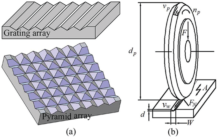
Schematic diagram of (a) V-groove arrays and (b) the UVAP principle for machining V-groove.
Angle correction of the polishing wheel
In this article, the polishing wheel is made of nano cerium oxide by high-temperature pressing which is much softer than the workpiece. Thus, if the angle of the polishing wheel’s V-shape section is the same as that of the V-groove, the edges of the V-grooves may be rounded because of the polishing wheel’s deformation during the UVAP processing, as shown in Figure 2(a), so the angle of the polishing wheel’s V-shape section should be smaller to ensure the sharpness of the V-grooves’ sharp top corner, as shown in Figure 2(b). In order to calculate the angle of the polishing wheel’s V-shape section, the contact simulation between V-groove and polishing wheel was carried out by finite element simulation analysis. Since the polishing wheel and V-grooves are axisymmetric structures, quarter contact mold was established to simplify calculation, as shown in Figure 3(a). In addition, the unit type is solid45, sweeping the grid with the sweep method, the polishing wheel as a flexible body, and the microstructured surface as a rigid body. The contact boundary conditions were established accordingly. The contact state between polishing wheel and V-groove is shown in Figure 3(b). When the angle of the polishing wheel’s V-shape section was not corrected, the polishing wheel’s material is extruded in the sharp top corner of the V-groove. However, through iterative calculation, the corrective angle is chosen to avoid the phenomenon of the material being extruded.
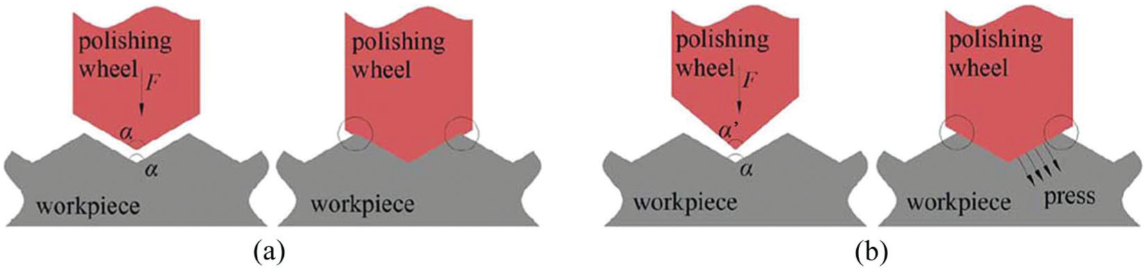
Sketch map of the effect of polishing wheel’s V-shape section angle on the sharp top corner of the V-groove: (a) no correct polishing wheel’s V-shape angle and (b) correct polishing wheel’s V-shape angle.
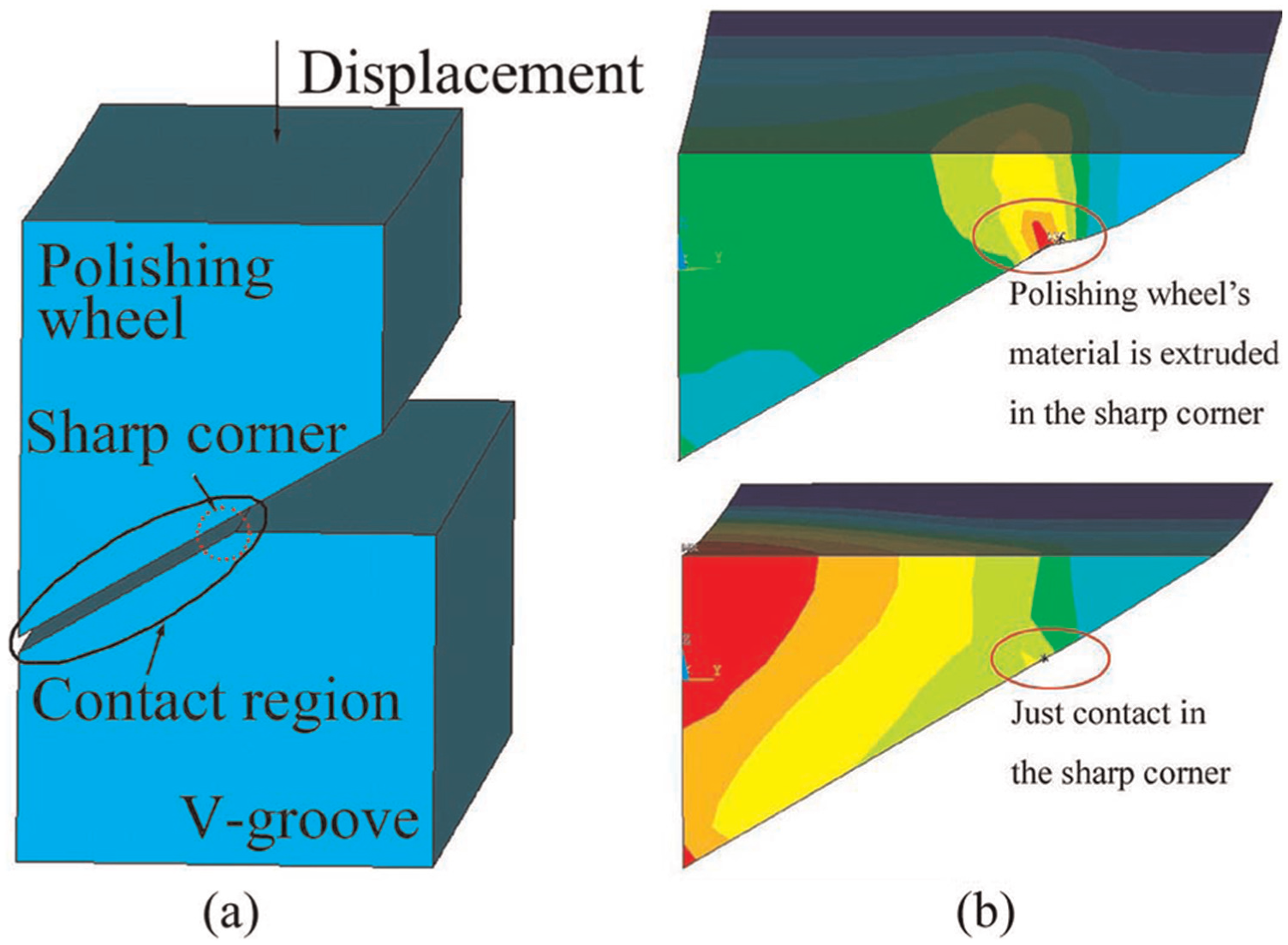
Quarter FEA (a) contact model and (b) contact state comparison before and after V-shape polishing wheel’s angle correction.
In the actual UVAP process, the polishing force is realized by adjusting the coordinate position of the vertical axis of the machine tool and is simultaneously measured by the force transducer installed beneath the vibration device. Therefore, the relationship between the angle of the polishing wheel’s V-shape section and the polishing force is shown in formula (1) according to the results of simulation

where αp is the angle of the polishing wheel’s V-shape section and F is the polishing force.
Profile correction of the polishing wheel
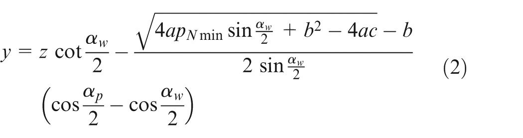
As shown in Figure 2, when the polishing wheel is in contact with the V-groove, the contact pressure will be produced in the contact region. Since the angle of the polishing wheel is corrected, the deformation of the polishing wheel leads to the unequal contact pressure p along the direction of the contact region, and the surface profile accuracy of the V-groove may be damaged by the unequal polishing pressure during UVAP process, as shown in Figure 4(a). Accordingly, the profile of the polishing wheel’s V-shape section was corrected to ensure the contact pressure maintaining consistently. As shown in Figure 4(b), the coordinate system for the deformation of the V-shape polishing wheel is established, where ΔY is the deformation of the polishing wheel, and αp and αw are the angles of the polishing wheel’s V-shape section and the V-groove’s two diffraction surfaces, respectively. The contact deformation of the polishing wheel can be described as the formula (2), where pNmin is the minimum contact pressure before the profile of the polishing wheel’s V-shape section was corrected. The constants a, b, and c are related to the polishing force
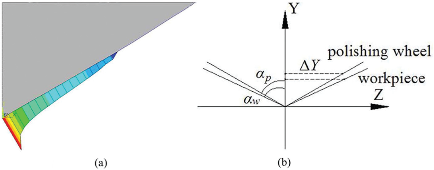
(a) Contact pressure before correct profile and (b) the contact deformation coordinate system of the polishing wheel.
In addition, the no corrected and corrected profiles of the polishing wheel’s V-shape section are compared in Figure 5(a). In order to guarantee the profile accuracy of the V-grooves, the machining interpolation trajectory is formulated according to formula (2) during the subsequent truing of the polishing wheel. Furthermore, the contact simulation analysis between the polishing wheel with the corrected V-shape section profile and V-groove was carried out again. As shown in Figure 5(b), compared with Figure 4(a), the contact pressure is more uniform after the V-shape section of the polishing wheel was corrected, and the profile accuracy of the V-groove can be better maintained by polishing using the corrected polishing wheel.
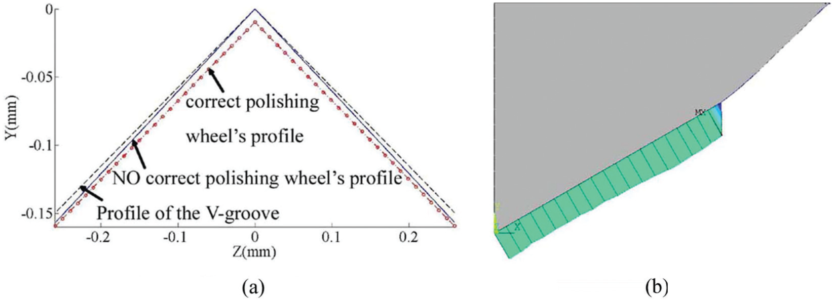
(a) V-shape section profile comparison before and after corrected profile and (b) the contact pressure after corrected profile of the polishing wheel.
Truing for polishing wheel
A nanometer grain-sized cerium oxide polishing wheel was applied in this experiment. The V-shape profile in the polishing wheel section can be trued by precision turning on machine with a diamond tool to minimize the run-out error and meanwhile to generate the accurate microstructured shape. The turning principle for V-shape polishing wheel is shown in Figure 6(a); the machining interpolation trajectory A-B and C-D were formulated according to formula (2), and the polishing wheel performed the interpolation movement while performed down feed motion. Before and after diamond truing, the section profile of polishing wheel was measured by a laser displacement measuring system, as shown in Figure 6(b). The shape of the profile of the polished wheel after polishing several grating surfaces had been damaged, and the top was also slightly worn. However, after precision turning by a diamond tool, the profile of the V-shape wheel was complete with a sharp top, as shown in Figure 6(b).
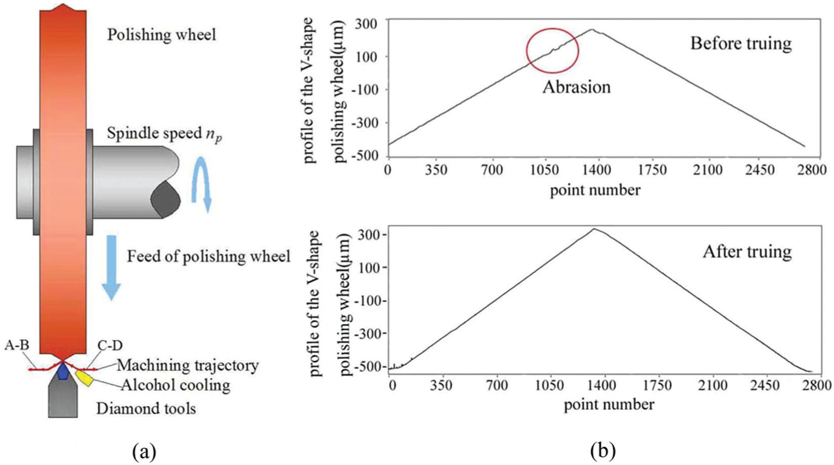
(a) Truing principle for V-shape polishing wheel and (b) the measured V-shape polishing wheel’s profile before and after truing.
Experimental setup of UVAP
The polishing experiments were performed on the same precision grinder (MUGK7120X5 horizontal spindle surface grinder) after grinding in order to avoid repositioning error of workpiece. As shown in Figure 7, the workpiece is fixed on the ultrasonic vibration tool head with bonding glue, and the force transducer is installed beneath to measure the three-dimensional forces acting on the microstructured surfaces. The polishing process is observed online by an optical microscope.
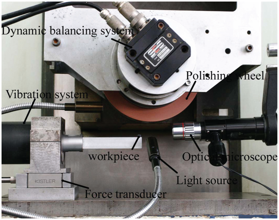
Experimental setup of UVAP.
The V-groove arrays were ground on the precision surface grinder before UVAP with designed individual groove’s depth of 150 µm and angle of 120°. An overview of the UVAP conditions is given in Table 1.
Experimental parameters of UVAP.
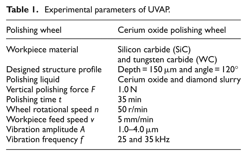
The polishing wheel rotational speed n is 50 r/min, the workpiece feed speed v is 5 mm/min, the polishing time t is 35 min, and the vertical polishing forces F is 1.0 N. There are two kinds of vibration frequency f such as 25 and 35 kHz, which are applied with the vibration amplitude A varying in the range of 1.0–4.0 µm.
Experiments results and discussions
Sharp top corner analysis of the grating arrays by UVAP
In this article, the angle of the polishing wheel’s V-shape section was corrected to ensure sharp top corner, and Figure 8 shows the top corners of the grating arrays polished by two kinds of the polishing wheel with no corrected angle and corrected angle, respectively. Accordingly, in Figure 8(a), the top corner is rounded seriously due to the deformation of the polishing wheel before correcting the angle of the polishing wheel. Nevertheless, the top corner is sharp after correcting the angle of the polishing wheel. In addition, the value of the arc radius R is used to characterize the sharpness of the top corner in this article. First, the profile of the grating was detected by a contact probe profilometer and then the detected data were imported into MATLAB to calculate the arc radius R. The calculated results show that the arc radius R after polished by the no corrected polishing wheel is 12 µm, while it can be decreased to 5 µm by correcting the angle of the polishing wheel’s V-shape section.
Top corners of the grating arrays comparison (a) before and (b) after corrected the angle of the polishing wheel.
Profile accuracy analysis of the grating arrays by UVAP
For the grating arrays, the profile accuracy is the angle deviation of the diffraction surface of the V-groove between the ground surface and polished surface. The specific profile accuracy analysis method for V-grooves is using a contact probe profilometer to detect the ground surface and the polished surface and then importing the test data into MATLAB to calculate the angle deviation. The shape contour of the ground surface, polished surface using the polishing wheel with no corrected profile, and the polished surface using the polishing wheel with corrected profile is shown in Figure 9. Through fitting calculation, the ground diffraction surface angle is 120.0415°; the diffraction surface angle of the V-groove polished by the polishing wheel with no corrected profile is 119.6533°, while the diffraction surface angle of the V-groove polished by the polishing wheel with corrected profile can be reached to 119.9768°, more closely to the ground result. Furthermore, the profile deviation of the V-groove polished by the polishing wheel with no corrected profile gradually enlarges from the top to the bottom of the diffraction surface, and the maximum deviation is 1.0487 µm at the bottom of the V-groove; however, the profile deviation distribution is relatively uniformly polished by the polishing wheel with corrected profile because of the equal contact pressure between the polishing wheel and the V-groove, and the maximum deviation is only 0.1768 µm.
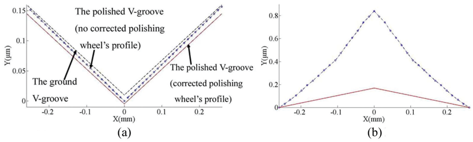
(a) Profile and (b) profile deviation of the V-groove after polishing.
UVAP of the grating arrays
UVAP of the grating arrays on silicon carbide is shown in Figure 10(a); the third V-groove microstructure is the ground surface, and the rest are the polished microstructured surface. According to the SEM images shown in Figure 10(b), the brittle fracture and some damages are generated on the ground surface and the top of the V-groove. However, the better surface quality can be generated through UVAP, and the brittle fractures have been completely removed. In addition, the surface roughness and profile were evaluated by a contact probe profilometer, and the evaluated results show that the surface roughness is less than 20 nm. Importing the profiler data into MATLAB to calculate the arc radius of the top and bottom of the V-groove, the calculated results show that arc radius on the top is less than 4.579 µm, and arc radius on the bottom is less than 20 µm.
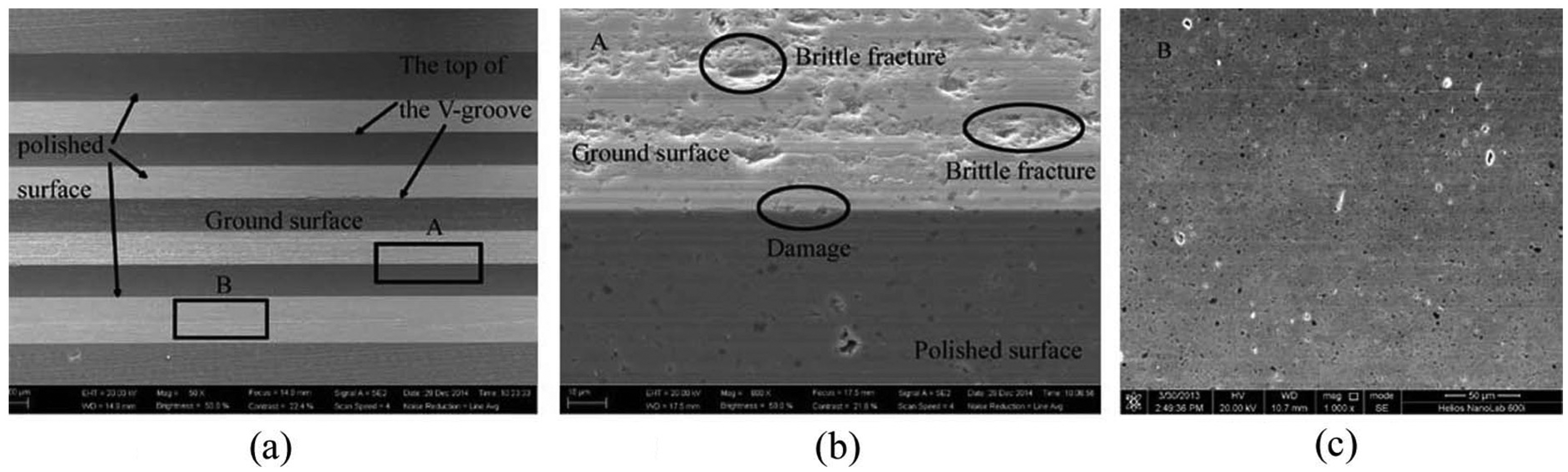
SEM images of the grating arrays on SiC: (a) grating arrays, (b) top of the grating array, and (c) polished grating surface.
Figure 11 shows the grating groove surface morphology measured by SEM through grinding and UVAP on binderless tungsten carbide, where Figure 11(a)–(c) shows the ground surface morphology and Figure 11(d)–(f) shows the polished surface morphology. According to the SEM images shown in Figure 11(a)–(c), the ground surface is mainly formed by plastic removal, and many scratches generated by plastic plowing are on the ground surface, but the top is sharp. However, as shown in Figure 11(d)–(f), through UVAP the grating microstructured surfaces quality are better, without scratches, the tops of the V-groove are not only complete but also equally sharp as that machined by grinding. Similarly, the surface roughness and profile were evaluated by a contact probe profilometer, and the angle deviation of the grating diffraction surface through grinding and UVAP is less than 0.1°.
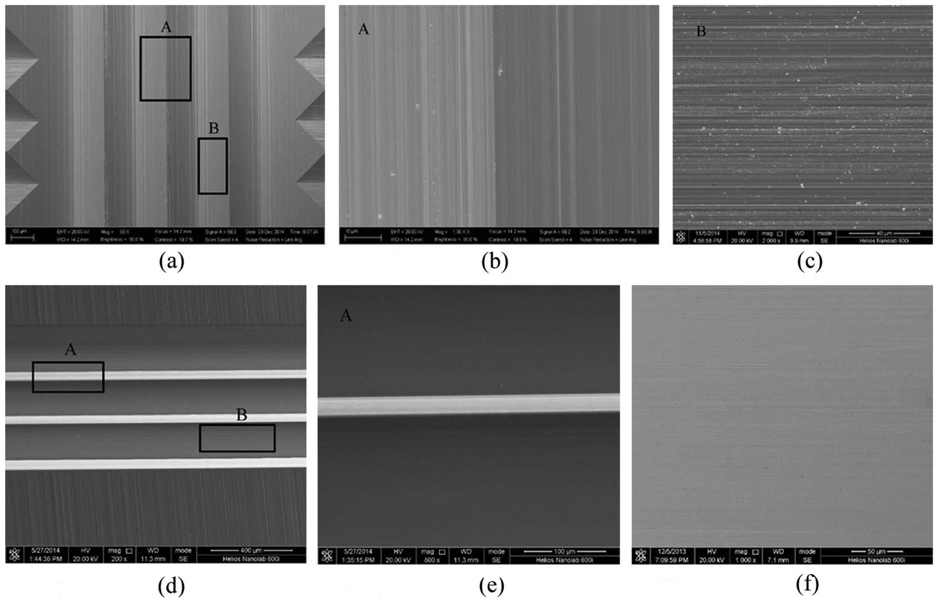
SEM images of the grating array on WC: (a) ground grating array, (b) ground grating top, (c) ground grating surface, (d) polished grating array, (e) polished grating top, and (f) polished grating surface.
UVAP of the pyramid array
UVAP of the pyramid arrays on silicon carbide is shown in Figure 12(a); the left third V-groove microstructure is the ground surface, and the rest are the polished microstructured surface. Figure 12(b) and (c) shows the V-groove surface and the top morphology measured by SEM through grinding. Multiple brittle fractures and damages are generated by brittle removal. The better pyramid microstructured surface quality is obtained by UVAP as shown in Figure 12(d)–(f). The brittle fractures generated by grinding have been removed, and the edge is complete without breaking, as shown in Figure 12(e). However, the diamond wheel’s wear in the grinding process leads to depth of each groove inconsistent so that the bottoms do not intersect at one point, as shown in Figure 12(f). Thus, it can be seen that the overall profile of the pyramid arrays is determined by the grinding process.
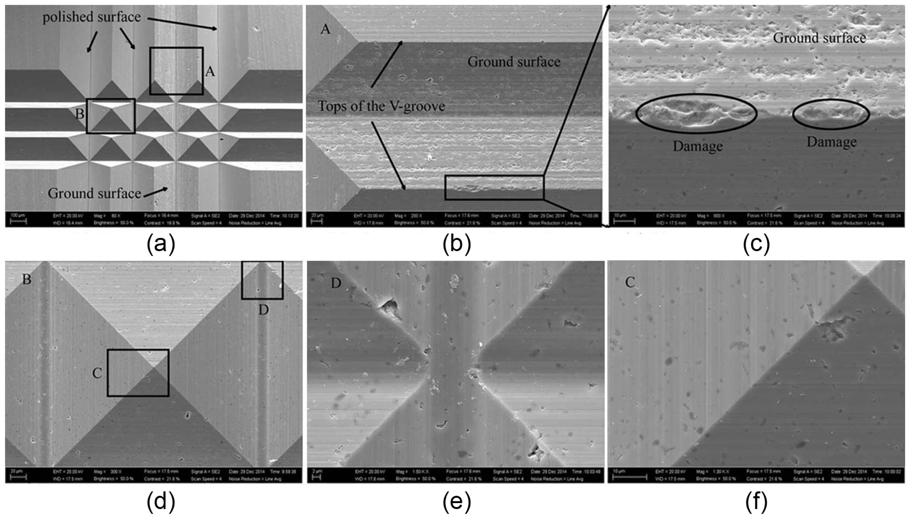
SEM images of the pyramid array on SiC: (a) pyramid array, (b) ground pyramid surface, (c) enlarged figure of the top, (d) polished single pyramid, (e) polished pyramid bottom, and (f) polished pyramid edge.
Figure 13 shows the pyramid arrays’ morphology measured by SEM through grinding and UVAP on binderless tungsten carbide, where Figure 13(a)–(c) shows the ground surface morphology and Figure 13(d)–(f) shows the polished surface morphology. Figure 13(a)–(c) shows that the pyramid arrays’ morphology is same as that of the grating arrays, and many grinding marks are generated by plastic removal. Similarly, the bottoms do not intersect at one point due to the diamond wheel’s wear. Compared with the ground surface, the polished surface of the pyramid arrays is smooth, consistent, edge sharp, and without damage, and the tops intersect at one point.
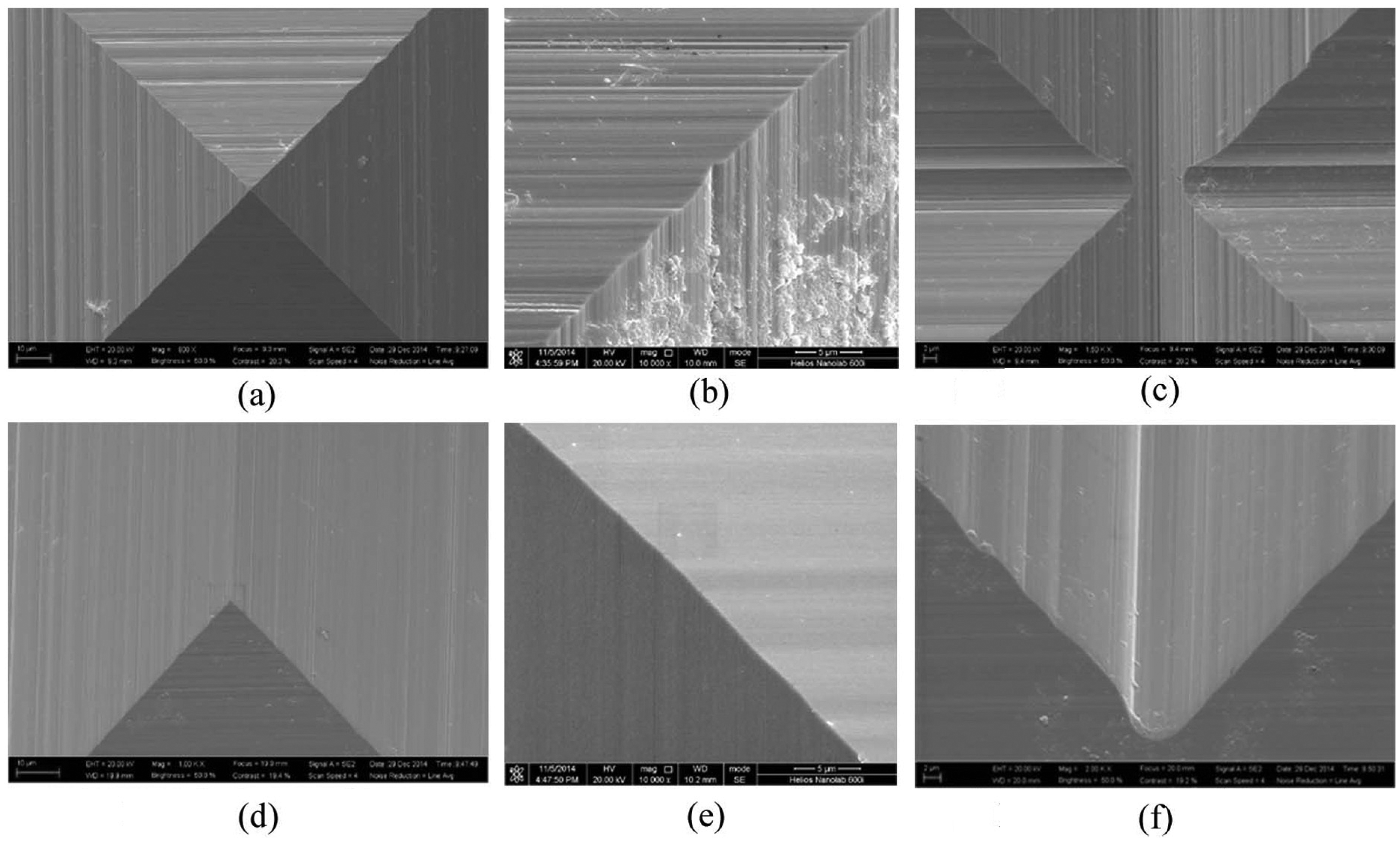
SEM images of the pyramid array on WC: (a) ground single pyramid, (b) ground pyramid edge, (c) ground pyramid bottom, (d) polished pyramid top, (e) polished pyramid edge, and (f) polished pyramid bottom.
Conclusion
UVAP of the V-groove arrays on hard and brittle materials are proposed in this article, and conclusions can be summarized as follows:
The angle of the polishing wheel’s V-shape section was corrected by the contact simulation analysis to ensure sharp top corner. The arc radius R is improved from 12 to 5 µm when the angle of the polishing wheel’s V-shape section was corrected.
The profile of the polishing wheel’s V-shape section was corrected to ensure the surface profile accuracy of the ground V-grooves. And the corrected profile formula was established and used for the subsequent polishing wheel truing.
The profile deviation of the V-groove polished by the polishing wheel with no corrected profile gradually enlarges from the top to the bottom of the diffraction surface, and the maximum error is 1.0487 µm at the bottom of the V-groove. However, the profile deviation distribution is relatively uniformly polished by the polishing wheel with corrected profile because of the equal contact pressure, and the maximum deviation is only 0.1768 µm.
The grating and pyramid surface quality has obviously been improved on SiC and WC through UVAP, and the edges and tops of the V-grooves are sharp and without damage by UVAP.
The experimental results indicate that the UVAP is an applicable and feasible technology for machining the V-groove arrays such as microstructures made of super hard-brittle materials typically represented by SiC and WC, in terms of higher efficiency and improved accuracy.
Footnotes
Declaration of conflicting interests
The author(s) declared no potential conflicts of interest with respect to the research, authorship, and/or publication of this article.
Funding
This work is supported by National Natural Scientific Foundation of China (NSFC, no. 51075093).