
Abstract
In this study, a hydroforming process is used for the manufacture of a bicycle frame tube, one side end of which is expanded to an acute-angled triangular shape from the initial tube, which has a regular triangular cross section. The end section of the expanding side is designed to be smoothly connected with the initial tube cross section to maintain sealing by the plunger. The tube hydroforming process is controlled using an axial feeding plunger and a pressure intensifier. Various load conditions can be applied to the initial tubes through these units. However, the experimental results showed that forming into the desired shape without bursting at the expanding area or shear cracking at other areas was not possible. These problems seem to occur because the circumferential propagation of plastic deformation is constrained by the triangular cross-sectional profile of the initial tube. To resolve this problem, less axial feeding should be supplied to the compressing zone compared with the expanding zone even in a single tube. In this work, besides conventional axial feeding, an additional axial feeding method by an end cam–shaped plunger is suggested to supply different axial feeding for each circumferential location of the tube. Finite element simulation and experimental studies are performed to verify the effectiveness of the concept.
Introduction
Many bicycle frame manufacturers are now using a tube hydroforming process to manufacture the main tubes in bicycle frames. The tube hydroforming process uses hydrostatic internal pressure and mechanical loading in the axial direction to form the tubes into the desired shapes. This process creates unique shapes and allows an even thickness to be retained in the material when the process is finished, thus creating an even lighter and stronger frame tube to be used in the frame system. In addition, the tube hydroforming process offers several attractive advantages compared to the conventional stamping process normally used to manufacture bicycle frames. These advantages include the following: cost and weight reduction, reduced dimensional variation, part consolidation, and fewer secondary operations. 1 –6
In this study, the tube hydroforming process was used for the manufacture of bicycle frame tubes from tubes with a triangular cross section rather than the circular cross section that is commonly used. One end of the target tube is expanded to an acute-angled triangular cross-sectional shape from the initial tube which has a regular triangular cross section as shown in Figure 1(a). The triangular cross section of the initial tube constrains the circumferential propagation of plastic deformation, which is necessary for tube expansion during hydroforming. Even when axial feeding is applied to the tube end by the plunger to improve the tube expansion ratio, excessive compression occurring at the areas that do not participate in tube expansion can cause shear cracking.
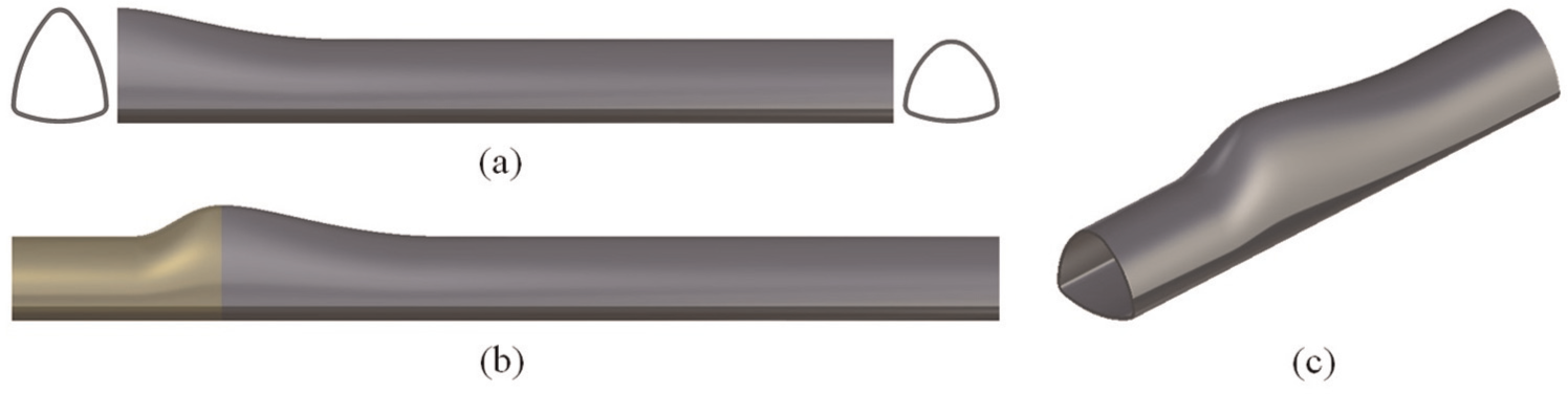
Target geometry after hydroforming: (a) bicycle frame tube shape, (b) tube shape modification to maintain sealing by plunger, and (c) reduction of the studied area.
In this work, besides conventional axial feeding to improve the tube expansion ratio, an additional axial feeding method controlled by the plunger shape is suggested to supply different axial feeding for each circumferential location of the tube. Finite element (FE) simulation and experimental studies were performed to verify the effectiveness of the concept.
Experimental setup and results
Figure 1(a) shows the final shape of the hydroformed tube that is used for the manufacture of the bicycle frame. The highest expansion ratio of the hydroformed tube is 18%. However, the actual tube expansion ratio increased to 30% when we consider the area that does not participate in the expansion due to the cross-sectional profile of the initial tube. The tube material used in this experiment is an as-extruded aluminum alloy. Because the as-extruded material exhibits poor formability and strong plastic anisotropy, achieving the desired expansion ratio of 30% is a difficult goal.
The end section of the expanding side, shown in Figure 1(a), was designed to be smoothly connected with the initial tube cross section in order to maintain sealing by the plunger as described in Figure 1(b). As can be seen in Figure 1(c), the studied area was reduced to enable forming using a compact hydroforming machine. The right-side plunger was fixed, and axial feeding was applied by only the left-side plunger to obtain similar test results when the entire tube was used.
The experimental setup for the tube hydroforming tests is presented in Figure 2. The applied loading paths, which show the relationship between the axial feeding and the internal pressure to the tubes, and the consequential ruptured expanded tubes are shown in Figure 3. When relatively high axial feeding was applied compared to the internal pressure, as in Path A, axially compressed material could not move smoothly into the expanding area and was continuously compressed at the bottom area of the tube until shear cracking occurred. On the other hand, when a relatively high internal pressure was applied compared to the axial feeding, as in Path B, bursting occurred in the expanding area. When axial feeding and internal pressure were applied based on the relationship between these factors, as in Path P, a rupture occurred in the rounded corner area. When axial feeding was applied to improve the tube expansion ratio, the rounded corner area at the bottom was the weakest region of the tube.
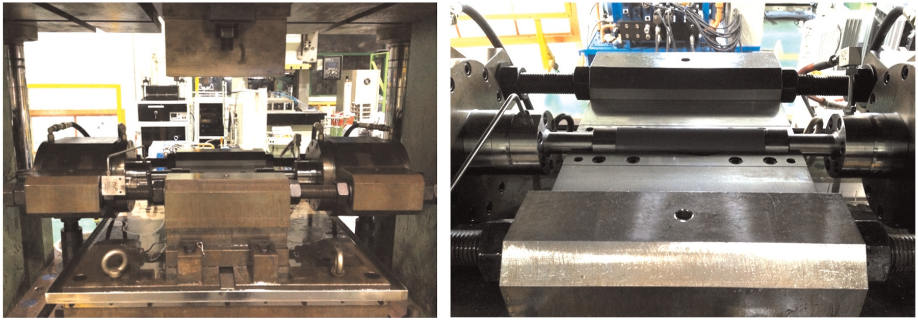
Experimental setup for tube hydroforming tests.
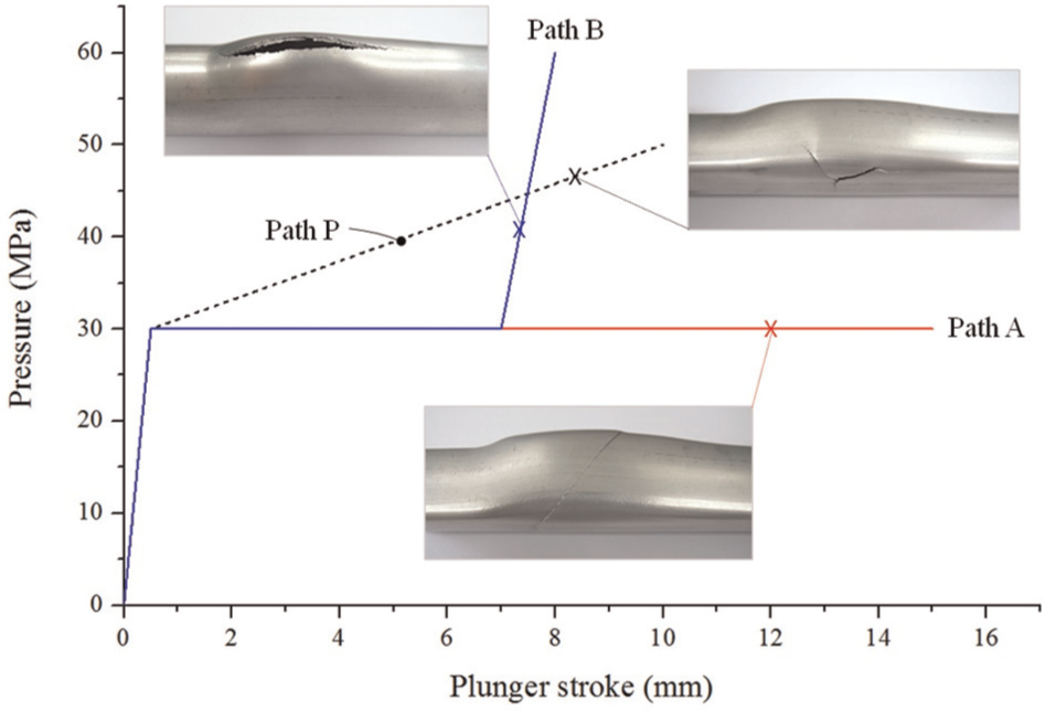
Ruptured expanded tubes under different loading paths.
Suggestion of new plunger design
To overcome the poor formability of as-extruded aluminum tubes and to increase the tube expansion ratio, axial feeding by plunger is essential during tube hydroforming. However, as seen in Figure 3, the experimental results of using an initial tube with a triangular cross section showed that excessive axial feeding can cause shear cracking in areas that do not participate in tube expansion due to the constraint of circumferential propagation of plastic deformation by the initial tube shape. Therefore, an effective method that can apply different amounts of axial feeding depending on the circumferential location of the tube should be devised to improve the tube expansion ratio.
To achieve this, we devised a new shape of plunger; this plunger has an end cam–shaped pushing surface as shown in Figure 4(a). Using the end cam–shaped tube pushing surface, the plunger can apply more axial feeding to circumferential locations that need more material to be fed and can minimize unnecessary feed.
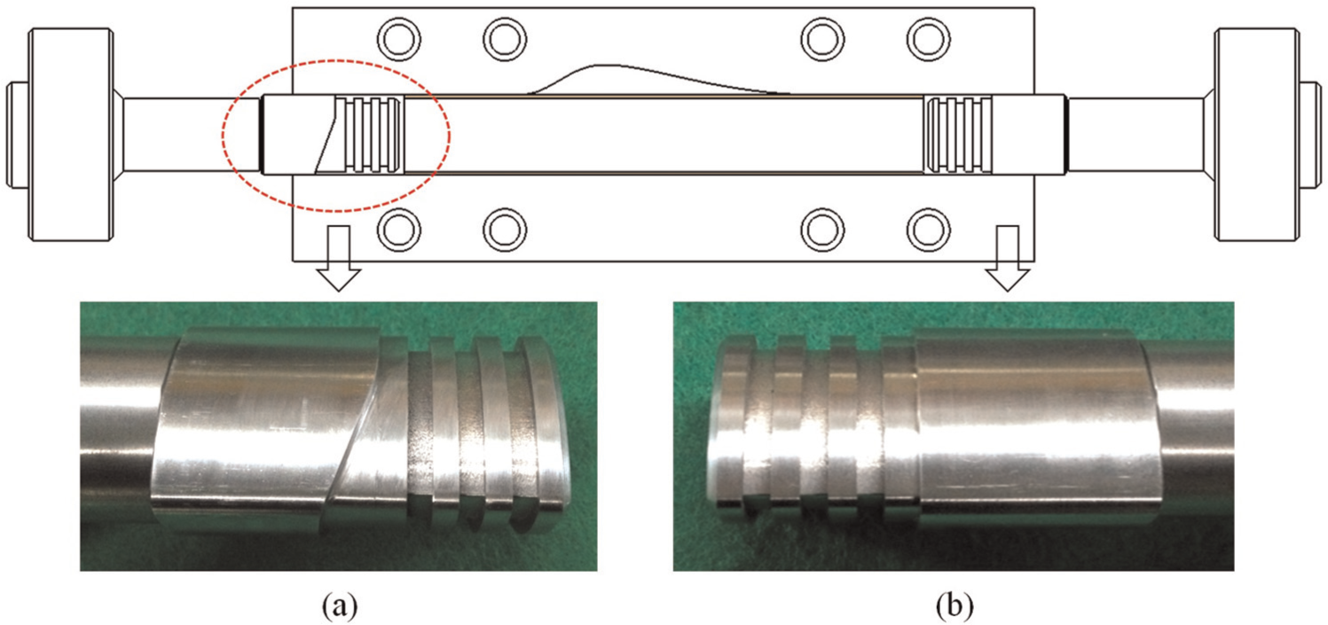
Schematic drawing of tube hydroforming with newly designed plunger: (a) end cam–shaped plunger and (b) conventionally shaped plunger.
Numerical verification
Simulation conditions of FE method
FE simulation of the tube hydroforming process was carried out using the commercial finite element analysis (FEA) software DEFORM-3D to verify the effectiveness of the newly devised plunger shape. Figure 5 shows the FE model used in the simulation. To reduce the computational time, only half of the tubes and dies were modeled. In the model, the tubular blank was assumed to be a rigid-plastic material and was divided into 7600 brick elements; the die and plunger were assumed to be rigid bodies.
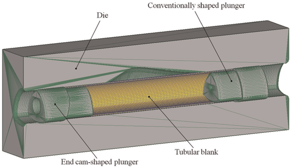
Finite element model for tube hydroforming simulation.
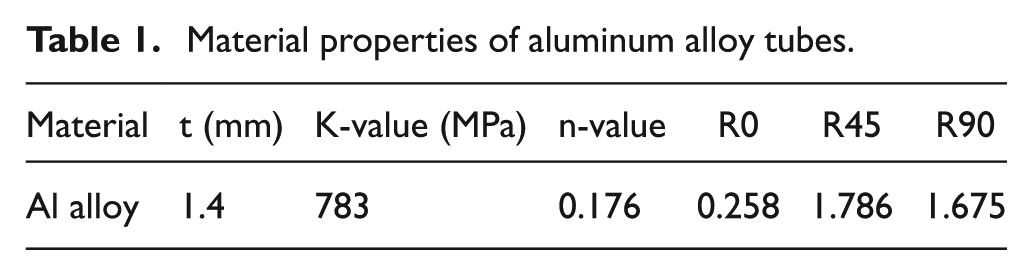
An as-extruded aluminum tube indicates strong plastic anisotropy. Thus, Hill’s quadratic yield function was used to describe the anisotropy of the tube. To determine the anisotropy coefficients for Hill’s quadratic yield function, standard uniaxial tensile tests were conducted using specimens that had been cut from tubes at 0°, 45°, and 90° with respect to the extrusion direction. The experimental true stress–strain curve, as shown in Figure 6, was fitted with Ludwik’s power law (σ = Kε n ) plastic model to define the material. The determined hardening parameters and anisotropy coefficients are reported in Table 1.
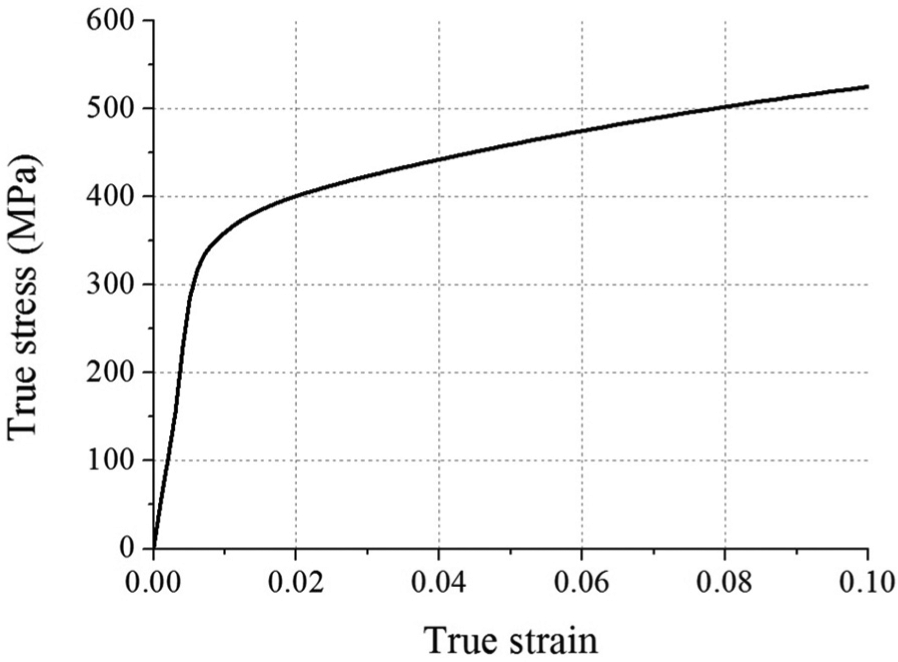
Flow stress curve of tube material.
Material properties of aluminum alloy tubes.
To define the proper anisotropic material directions of elements, every element of the tubular blank was assigned its own local coordinate system. In the local coordinate system, the x-direction is the same as the axial direction of the tubular blank, and the z-direction is the same as the thickness direction of the tubular blank.
Figure 7 shows the loading path applied to the simulation. As mentioned above, axial feeding was applied by using only the left-side plunger.
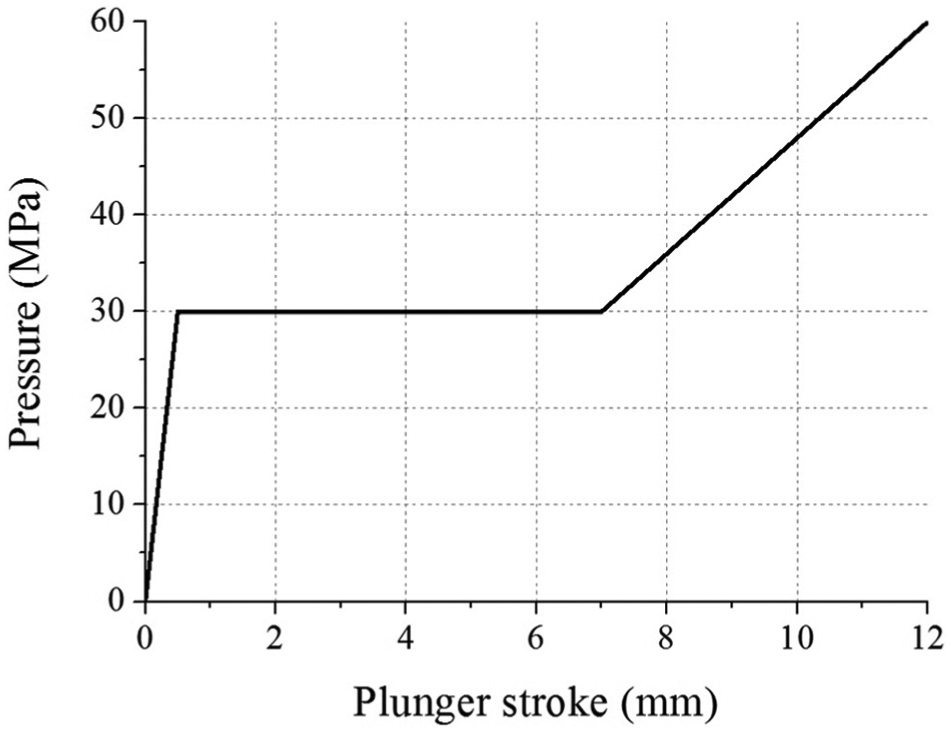
Loading path for simulation.
Validation of FE model
The established FE model was validated by comparing the results between simulation and experiment. Figure 8(a) shows the comparison results of the bulge height along the axial direction of the tube, and Figure 8(b) shows that of the thickness distributions at the cross section of the expanded zone. Both these results show an acceptable agreement between FE simulation and experiment.
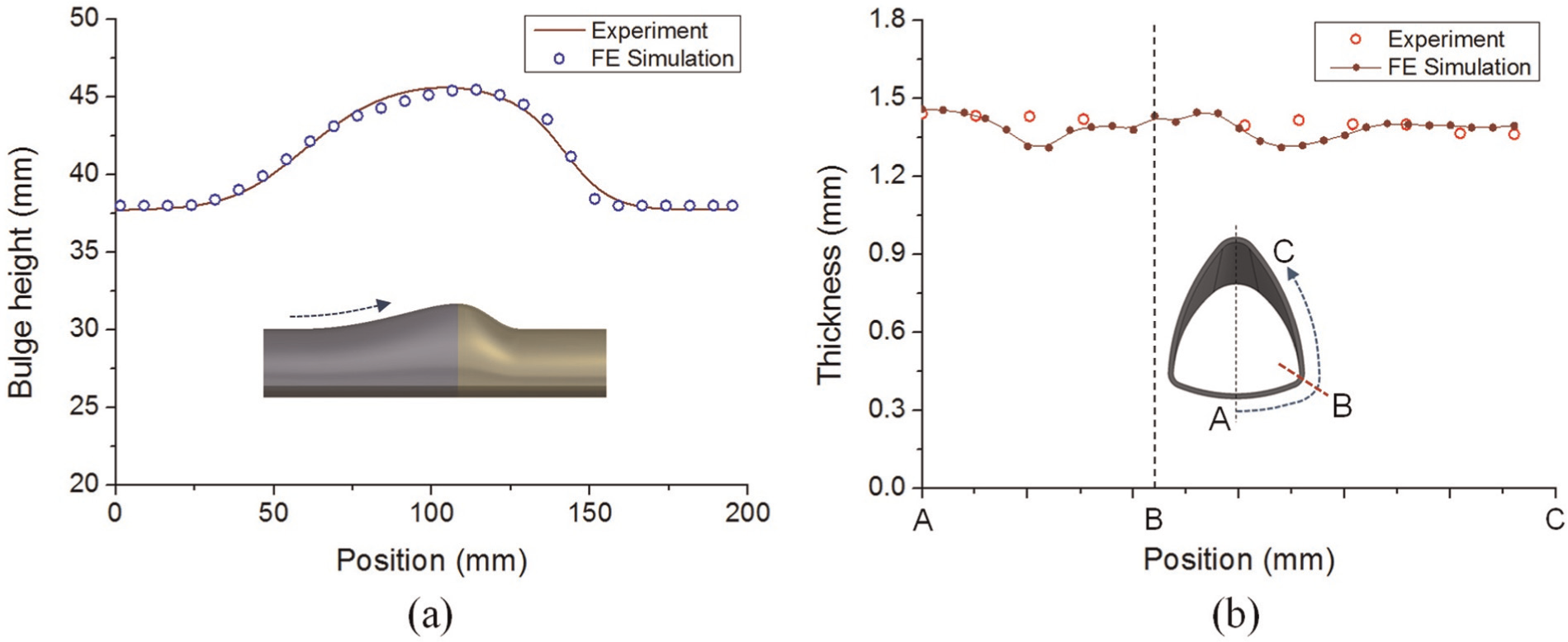
Comparisons between FE simulation and experiment: (a) bulge height distributions and (b) thickness distributions.
Simulation results
Figure 9 shows the selective material feeding mechanism of the end cam–shaped plunger. As can be seen in Figure 9(b), the tube end is gradually deformed along the end cam–shaped pushing surface of the devised plunger as the hydroforming progressed. Due to the end cam–shaped pushing surface, we can assign a different axial feeding starting time depending on the circumferential location of the tube.
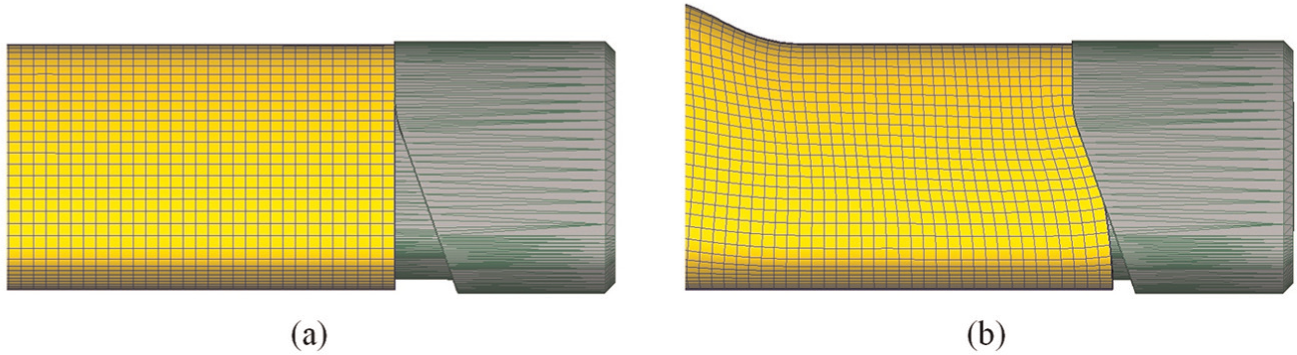
Selective material feeding mechanism of end cam–shaped plunger: (a) initial tube end shape and (b) deformed tube end shape.
The contours of effective strain after hydroforming calculated when the two differently shaped plungers were used are shown in Figure 10, and Figure 11 shows the effective strain distributions along path ABC at the cross section of the expanded tubes. With the conventionally shaped plunger, large effective strain was observed on the bottom area where share cracking had initiated in the experiments. Meanwhile, with the end cam–shaped plunger, there was less effective strain of the tube than with the conventionally shaped plunger.
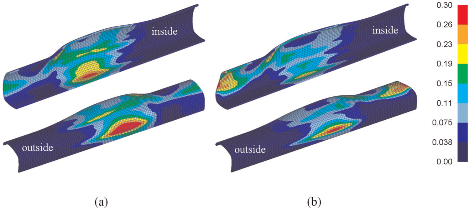
Calculated contours of effective strain after hydroforming using (a) conventionally shaped plunger and (b) end cam–shaped plunger.
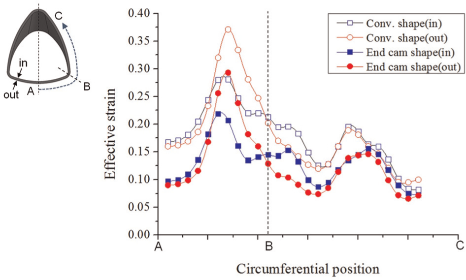
Effective strain distributions of expanded tubes.
The effect of the end cam–shaped plunger can be clearly observed from the contours of the strain component based on the local coordinate system. Figure 12 shows the x-directional component of the strain, which is the same as the axial strain of the tube. As seen in the figure, the compressive axial strain occurs throughout the entire tube under the employed loading path. By using the end cam–shaped plunger, the compressive axial strain at the bottom area can be reduced by more than 6% compared to the case of using the conventionally shaped plunger. Figure 13 shows the z-directional component of the strain, which is the same as the thickness strain of the tube. As the figure shows, compared to the case of using the conventionally shaped plunger, the maximum thickness strain (thinning) on the rounded corner area can be reduced by more than 5% by using the end cam–shaped plunger.
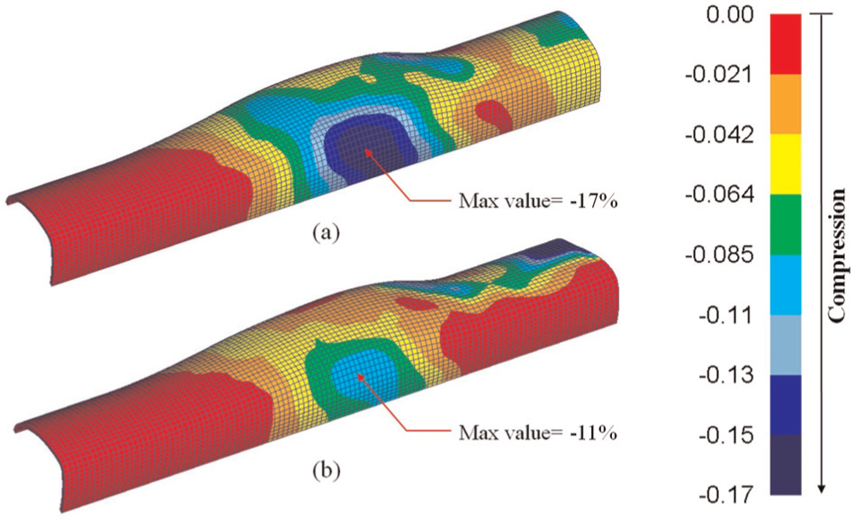
Calculated contours of x-directional strain component based on local coordinate system when using (a) conventionally shaped plunger and (b) end cam–shaped plunger.
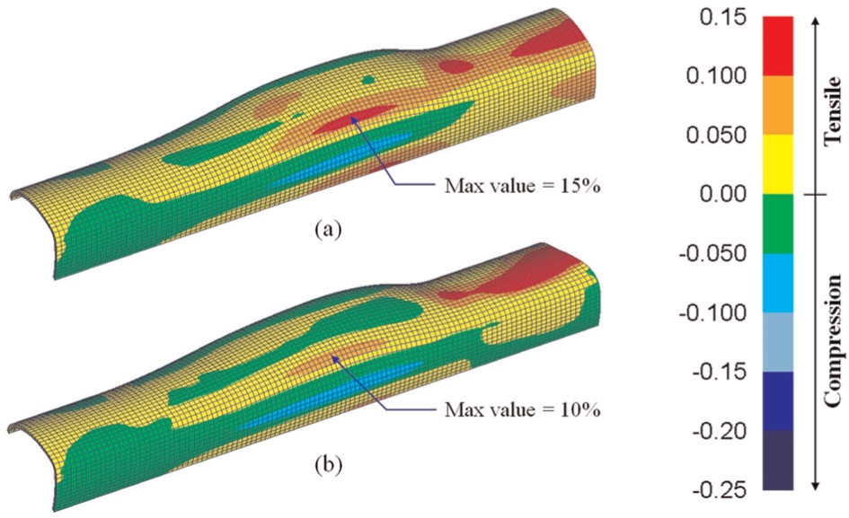
Calculated contours of z-directional strain component based on local coordinate system when using (a) conventionally shaped plunger and (b) end cam–shaped plunger.
Figure 14 shows the thickness distributions along path ABC at the cross section of the expanded tubes. When the end cam–shaped plunger is used, the deformed tube shows a more uniform thickness distribution than when the conventionally shaped plunger is used.
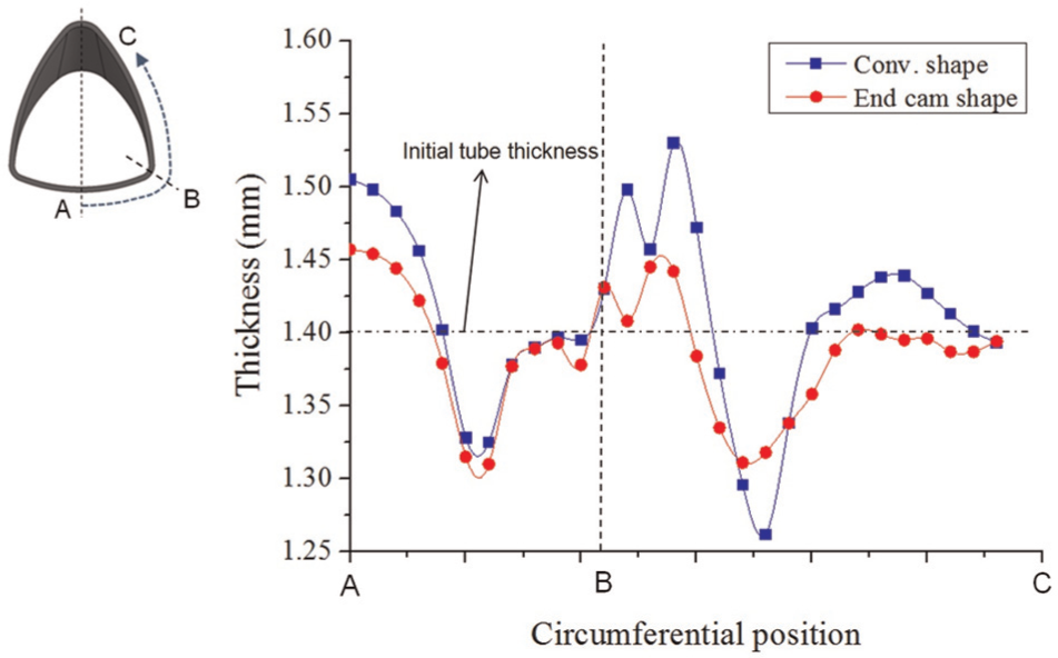
Thickness distributions of expanded tubes.
Therefore, it is concluded that the devised end cam–shaped plunger can effectively increase the axial feeding limit by preventing shear cracking in the areas that do not participate in expansion. The tube expansion ratio is also expected to improve due to the increased axial feeding limit.
Experimental verification
Figure 15 shows the hydroformed tube shape after the end cam–shaped plunger was used. The tube end on which feeding was applied was deformed along the end cam–shaped contact surface of the devised plunger.
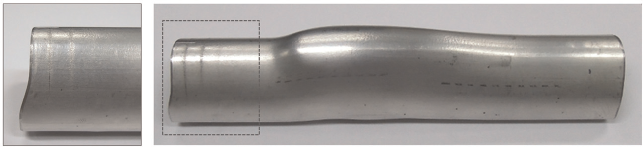
Hydroformed tube shape using end cam–shaped plunger.
Figure 16 shows the experimental results of the tube hydroforming process applying axial feeding using the conventionally shaped plunger and the devised end cam–shaped plunger. The positions at which ruptures occurred on the tube, depending on the loading path, are marked with the letter x. When axial feeding of 7 mm was applied in the early stage of forming while a pressure of 30 MPa was maintained, the end cam–shaped plunger improved the rupture limit under every loading path (A–D). The results show that by using the end cam–shaped plunger, more axial feeding can be exerted on the tube, thus improving the tube expanding ratio. However, there is no effect when relatively high internal pressure is applied in the early stage of forming, as in Path P.
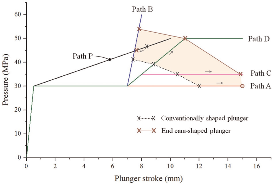
Rupture limit changes depending on the plunger type.
Figure 17 shows the thickness distributions from bottom to top at the cross section of the expanded tube. When the end cam–shaped plunger is used, the deformed tube shows a more uniform thickness distribution than when the conventionally shaped plunger is used. The occurrence probability of shear cracking at the bottom area of the tube and that of bursting at the top of the tube could be reduced by using the end cam–shaped plunger.
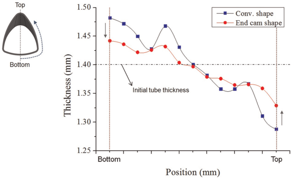
Thickness distributions of expanded tubes.
Although the achievement of the target-shaped tube using the tube hydroforming process failed due to the poor formability of the as-extruded tube material, the effectiveness of the devised end cam–shaped plunger on increasing the rupture limits of the tubes was validated by experimental and numerical studies.
Summary
In this study, a tube hydroforming process was used for the manufacture of aluminum bicycle frame tubes from initial tubes with a triangular cross section rather than the circular cross section that is commonly used. One end of the target tube was expanded to an acute-angled triangular cross-sectional shape.
To overcome the poor formability of as-extruded aluminum tubes and to increase the tube expansion ratio, axial feeding was carried out. However, the experimental results showed that excessive axial feeding can cause shear cracking in areas that do not participate in tube expansion due to the constraint of circumferential propagation of plastic deformation by the initial tube shape.
In this study, to improve the tube expansion ratio, we devised a new shape of plunger that has an end cam–shaped pushing surface that can apply different amounts of axial feeding depending on the circumferential location of the tube.
Experimental and numerical studies verified that the devised end cam–shaped plunger effectively increases the axial feeding limit by preventing shear cracking in areas that do not participate in expansion. The tube expansion ratio is also expected to improve due to the increased axial feeding limit.
Footnotes
Declaration of conflicting interests
The authors declare that there is no conflict of interest.
Funding
This research received no specific grant from any funding agency in the public, commercial, or not-for-profit sectors.