
Abstract
An aero-engine blade is the typical thin-walled workpiece with low rigidity. The machining accuracy of the aero-engine blade with sculptured surfaces has been a research focus in the aviation industry. This article presents a new cantilever grinding process for the high precision machining of aero-engine blade. Only one end of a blade is fixed and the other end is free in order to eliminate the deformation of blade caused by over-positioning. Moreover, the vibration of aero-engine blade can be reduced so that the surface quality of blade can be improved in the grinding. The grinding parameters are optimized for the low deflections of blade. The types of tool path are also discussed in this article. Finally, the computer numerical control machining examples are implemented. The measurement results show that the profile errors of suction/pressure surface machined by the proposed process do not exceed 0.02 mm. And the machining accuracy of leading/trailing edge with a radius of about 0.05 mm is acceptable.
Introduction
Blades are the typical thin-walled workpieces, which are important components of an aero-engine. The surface quality of the blades can influence the performance of aero-engine. The high precision machining technology of aero-engine blade is important for the development of aviation industry, which represents the comprehensive national strength. 1
It is almost impossible to avoid the deformation of aero-engine blade in the computer numerical control (CNC) machining. So many literatures are published for investigating how to machine the blade or thin-walled workpiece with low deformation.
The fixture is necessary in the machining process. But over-positioning would bring errors caused by clamping force. Chen et al. 2 indicated that the fixture layout and clamping force could affect the distribution and value of machining deformation. And a model with multi-objectives was established and optimized for reducing the machining deformation and improving the distribution condition. Liu et al.3,4 proposed a method for optimizing the number and positions of locators by finite element method in the machining of a workpiece with low rigidity. A new fixture layout was obtained with fewer locators, which could ensure the same machining precision. Wang et al.5,6 first analyzed the locating error and machining error of a turbine blade. Then the suggestions were given to decrease the locating error. And the elastic deformation of a fixture and turbine blade system was analyzed by finite element method considering many factors. 6 Methods were studied in the literatures2–6 for offering an optimal fixture layout and proper clamping force, which could control the deformation of workpiece.
Shan et al. 7 suggested a new strategy for improving the rigidity of aero-engine blade in the finishing stage. The geometry of blade was reconstructed in the roughing and semi-finishing stage for better rigidity of blade, which was managed by adopting uneven offset values along the radial and cross-sectional direction. So the rigidity of blade in the finishing stage was improved, and a better machining accuracy could be achieved, even though only one rabbet was fixed. The negative influence of clamping force on the blade surfaces was also eliminated.
Bera et al. 8 introduced the previous works about reducing the deformation of thin-walled workpiece. The previous research attempts were divided into three categories including the process design approach, the online adaptive control approach and the off-line tool path modification approach. Then a force model was established for predicting the tool deflection and the deformation of workpiece, which were compensated subsequently by modifying the tool path. Habibi et al. 9 gave a review of researches about tool deflection and error compensation. A special software was used to generate the compensated tool path. Methods were proposed in the literatures8,9 for generating the optimal tool path with error compensation to reduce the deformation of workpiece. Lee et al.10,11 analyzed and compared the deflections of thin plate machined by four cutting orientations with different cutting directions. Lee et al. 11 offered that the cutter orientation of vertical outward with tilt angle of 45° was the best cutting strategy in high-speed ball end milling of cantilever-shaped thin plate. But the error compensation was not taken into account in their work.
Wan et al. 12 presented three methods for selecting the feed per tooth and depth of cut simultaneously. Appropriate cutting parameters were offered. Ryu and Chu 13 analyzed the effects of tool teeth numbers, tool geometry and cutting conditions on the form error of side wall. Optimal method for reducing errors was suggested. Methods were presented in the literatures12,13 for optimal cutting conditions with the appropriate cutting force.
As previously mentioned, the problem of deformation in the machining of thin-walled workpiece attracted many attentions, and many findings had been obtained. But the high performance of aero-engine demanded the increasing requirements on the machining precision and efficiency at the moment. Denkena et al. 14 presented a status review about five-axis grinding of sculptured surfaces with toric tools. A better shape accuracy and surface quality could be obtained using grinding wheels. So this article presents a grinding process with the cantilever fixation of aero-engine blade by considering the theory of cantilever beam and the advantages of grinding. This grinding process can improve the machining precision of blade in the finishing stage with improved machining efficiency.
The remainder of this article is organized as follows. The cantilever grinding process is discussed in section “Cantilever grinding of aero-engine blade.” Machining examples are implemented in section “Machining examples” to prove the availability and effectiveness of cantilever grinding process. Conclusions are provided in section “Conclusion.”
Cantilever grinding of aero-engine blade
Cantilever grinding is a process where only one end of the blade is fixed and the other end is free while machining using a grinding wheel. The deformation of the blade can decrease due to the advantages of grinding, such as the ability to remove small allowance and the low continuous grinding force.
Cantilever grinding process is capable of machining the aero-engine blade with the reduced deformation. The study is carried out on the fixation of blade and the grinding strategy.
Fixation of aero-engine blade
As shown in Figure 1(a), the two ends of the aero-engine blade are all fixed in the milling or grinding to limit the deformation. But it would bring new errors caused by clamping force. When the blade is unfixed, the clamping stress would be released, which can cause the new deformation. The deformation of blade caused by the residual stress is also restricted because of the over-positioning in the machining process. But it would reduce the machining accuracy after the fixture is removed. The clamping force and residual stress can bring the deformation of aero-engine blade.15–17 So the compensation methods are popular in the machining of blade with two ends fixed.
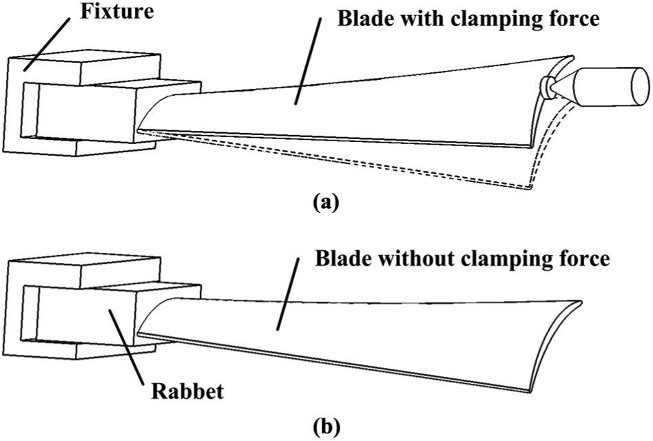
Fixation of aero-engine blade: (a) fixation with over-positioning and (b) cantilever fixation.
When only one rabbet of the blade is fixed, there is no additional force on the surface of blade, as shown in Figure 1(b). So the errors brought by clamping force could be eliminated in the cantilever grinding process. And the complicate fixture can increase the unnecessary machining cost. 15 Furthermore, the residual stress of material can be released in the machining process so that the deformation of blade decreases. The deformation of the blade is related to the cutting force directly. The ability to remove trace amounts of materials in the grinding is helpful for controlling the deformation of blade. The grinding force can be optimized by grinding parameters and grinding process with a certain grinding efficiency. Then the aero-engine blade with lower deformation and higher machining quality can be obtained.
Machining of leading/trailing edge
The leading edge and trailing edge are important for the aerodynamic performance of the aero-engine blade. 18 The tool path for machining leading/trailing edge could be generated around the circumference or following the axial direction, which are illustrated in Figure 2(a) and (b), respectively.
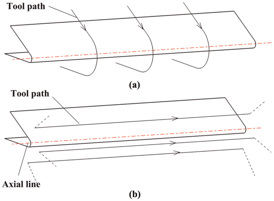
Grinding direction for leading/trailing edge: (a) tool path around the circumference and (b) tool path following the axial line.
As shown in Figure 2(a), the tool path is generated around the circumference with the great acceleration between the adjacent tool position points because the radius of leading/trailing edge is small. It would deteriorate the machining precision and make overcut on the leading/trailing edge.
The tool path shown in Figure 2(b) is generated following the axial direction of leading/trailing edge. That the cutter moves with a lower acceleration is better for the surface quality of leading/trailing edge. So the grinding direction is along the axial line in the cantilever grinding of leading/trailing edge. And the tool path can be generated by iso-scallop or iso-parameter method when the acceleration is acceptable.
Machining of suction/pressure surface
The grinding strategy and machining parameters for suction surface and pressure surface are very important. The grinding direction of tool path for suction/pressure surface is parallel with that for leading/trailing edge in order to avoid marks on the surface of blade. The following experiments are carried out to study the process of cantilever grinding.
A thin-walled plate (material: supper alloy GH4169) is fixed on the fixture, as shown in Figure 3. The cantilever length denoted by H is 50 mm and the width of plate denoted by W is 13 mm. T is the thickness of plate and t denotes the thickness of plate after machining. w is the interval between the adjacent tool paths called strip width. But the actual number of tool path is not illustrated in Figure 3.
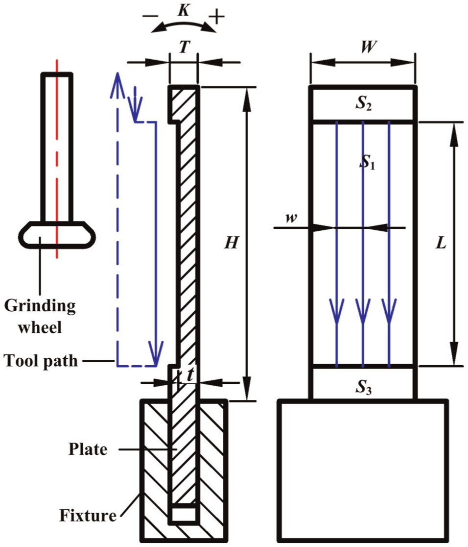
Single machined plane with grinding wheel.
Then the plane S1 is machined by a grinding wheel and the length denoted by L of plane S1 is 40 mm. S2 and S3 are the planes that would not be machined. The maximum deviation denoted by K between the planes S2 and S3 in the thickness direction is measured after grinding, which is partly in response to the deformation of plate. And the sign of K is also shown in Figure 3.
As shown in Figure 3, single plane is machined along the tool path. The cubic boron nitride (CBN) grinding wheel is used in this article. The wheel speed is 33.0 m/s and the feed rate is 1200 mm/min, which are uniform in the experiments of section “Cantilever grinding of aero-engine blade.” Five thin-walled plates are machined to study the influences of grinding depth ap and thickness T on the deformation. The detailed results are shown in Table 1.
Results of single-plane grinding (mm).
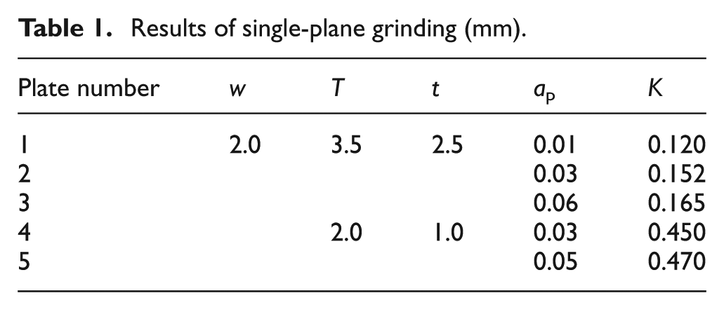
According to Table 1, the deformation of thin-walled plate is related to the thickness T of plate and the grinding depth ap. The greater ap is, the greater the deformation of plate is. The grinding force would become greater with the increase in ap, so the deformation of plate is greater. The thinner plate has the lower rigidity, so the deformation of a plate with smaller T is greater with the same grinding force. It is obvious that the grinding process and parameters in this experiment are not available for the blade using cantilever fixation according to the unacceptable deformation.
The most important study on cantilever grinding process is to find the proper strategy that can reduce the deflections of thin-walled plate with the same grinding efficiency. Two other experiments are designed as follows to achieve this objective.
A new experiment is implemented, as shown in Figure 4. Double planes of the plate are machined as an actual blade. The front plane is first machined with grinding depth ap using grinding wheel along the similar tool path in the first experiment. Then the back plane is machined with the same machining parameters and the similar tool path. This process is called the sequential grinding of double planes.
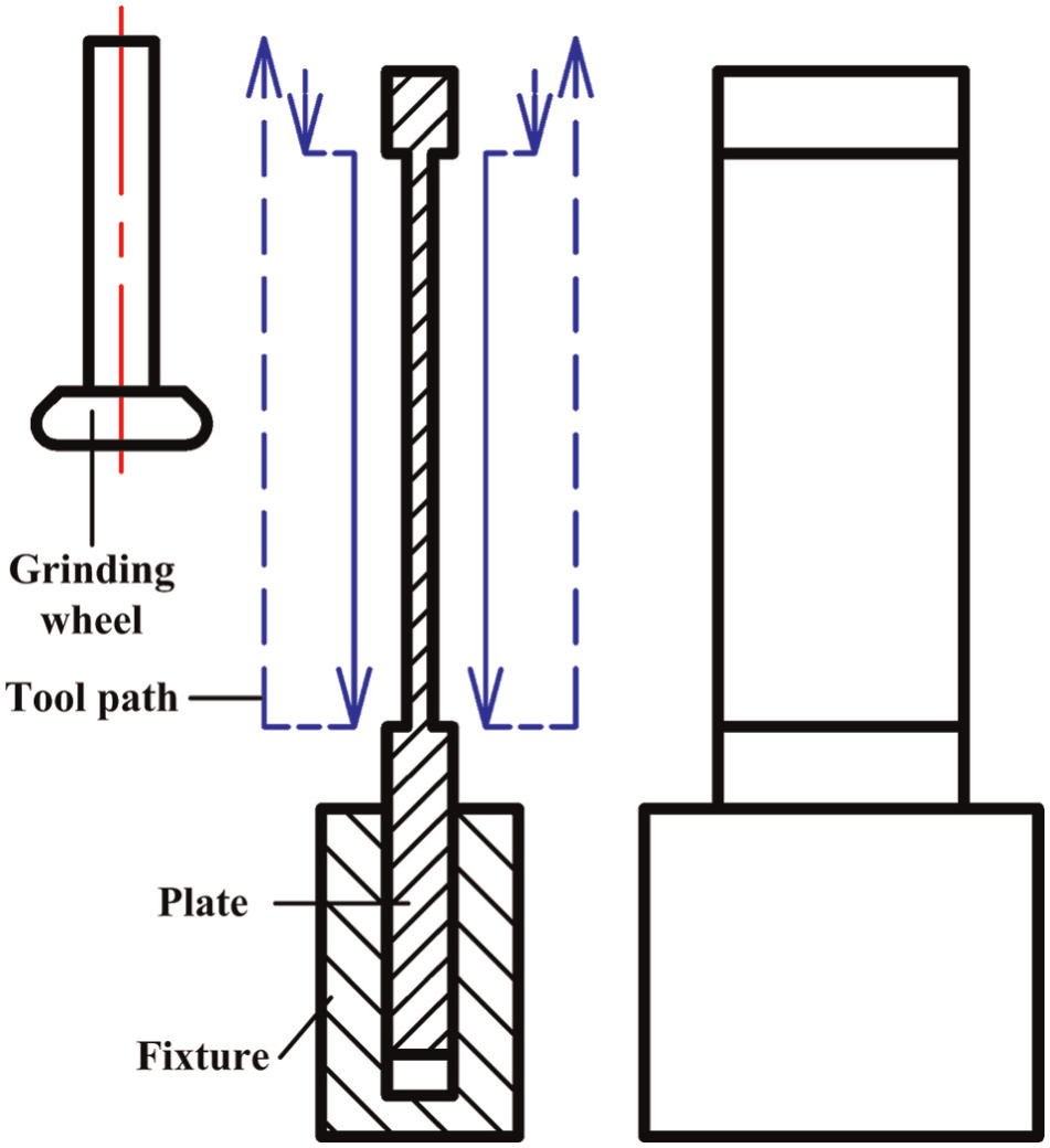
Double machined planes with the sequential tool path.
The plate is machined with two groups of machining parameters, as shown in Table 2 when t is equal to 1.44 and 1.28 mm, respectively. The measure results of K are also shown in Table 2. Other parameters are the same as in the first experiment.
Results of double-plane grinding (mm).
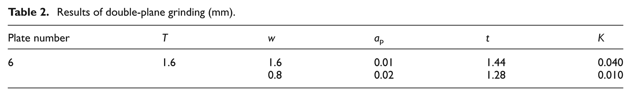
Under the same material removal rate (MRR), the deformation of plate with the smaller strip width and the greater ap is lower according to Table 2. This is a useful conclusion for cantilever grinding. So the machining parameters with the smaller strip width and the greater ap are selected in the cantilever grinding process.
In order to improve the rigidity of plate in the grinding process, the symmetrical tool path, as shown in Figure 5, is applied in the third experiment. The front plane and the back plane are machined in turn with the same machining parameters along the symmetrical tool path, which is different to that in the second experiment. And this process could be named the symmetrical grinding of double planes.
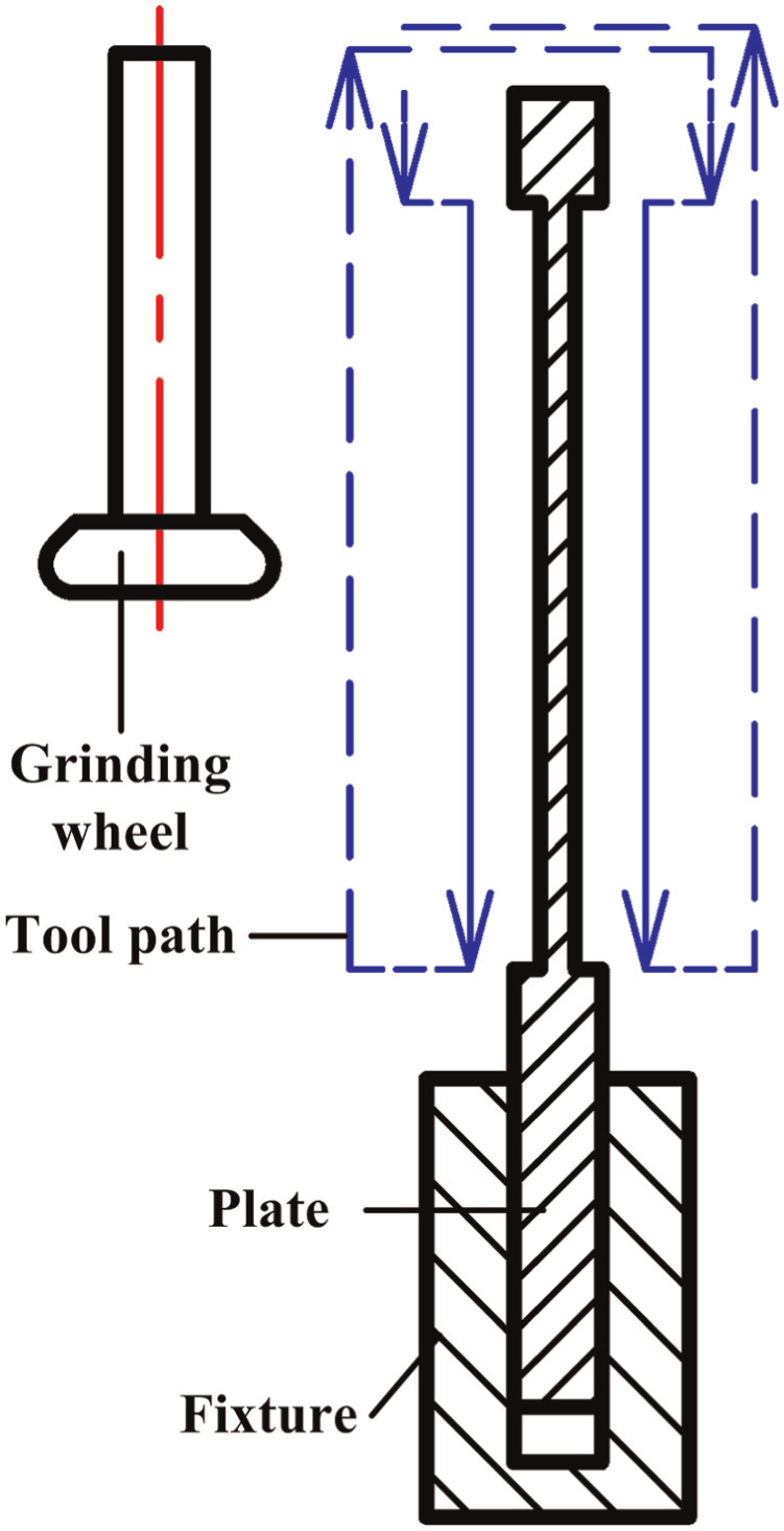
Double machined planes with the symmetrical tool path.
The values of K are measured when t is equal to 3.3, 2.9 and 2.5 mm, respectively. The results are shown in Table 3.
Results with symmetrical tool path (unit: mm).
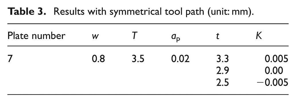
According to Table 3, the deformation of this plate is small using the symmetrical grinding method. It is because the rigidity of plate using the symmetrical grinding is better than that in the sequential grinding. This experiment proves that the deformation of plate could not exceed 0.01 mm with the MRR of 24.0 mm 3 /min for the optimized grinding parameters.
According to the machining results of three experiments, the machining parameters with smaller strip width w and greater grinding depth ap are better for machining the plate with low deformation if the MRR is same. And the rigidity of plate is an important factor that influences the deformation. The symmetrical grinding style with optimized machining parameters can decrease the deformation of plate further. So the cantilever grinding process in this article can be used for machining the thin-walled plate with low deformation.
Machining examples
Machining examples are implemented in this section for proving the effectiveness of cantilever grinding process.
Three-axis cantilever grinding of leading/trailing edge
The leading/trailing edges (material: 1Cr11Ni2W2MoV) with different radii are machined by the three-axis cantilever grinding process. The machining effectiveness of leading/trailing edge is shown in Figure 6.
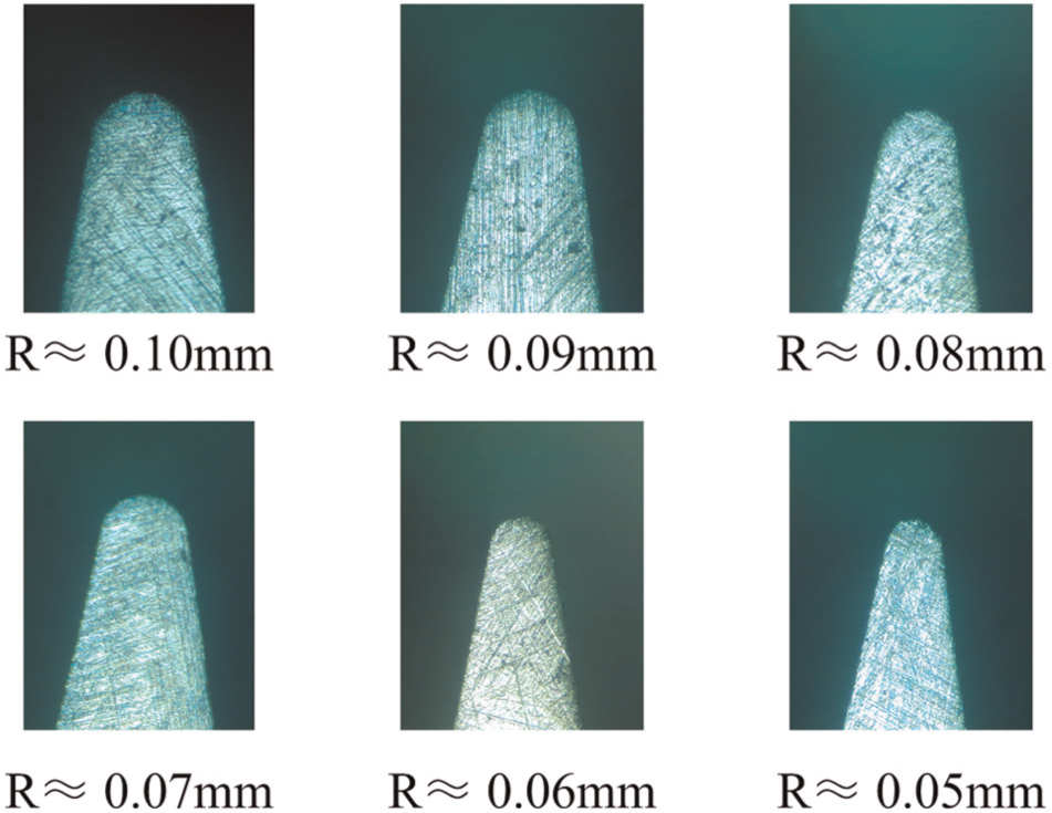
Cross section of leading/trailing edge.
The tool path is generated by iso-parameter method and the scallop height does not exceed 0.001 mm. The speed of CBN grinding wheel is 33.0 m/s and the feed rate is 1200 mm/min. The profile of leading/trailing edge with small radius is satisfying.
Three-axis cantilever grinding of a ruled surface
As shown in Figure 7, a ruled surface (material: 1Cr11Ni2W2MoV) with a weak joint is machined using the three-axis cantilever grinding process. The height of grinding area is 30 mm. And the weak joint is 9 mm (width) × 5 mm (height) × 2.5 mm (thickness). The sequential grinding style in section “Cantilever grinding of aero-engine blade” is used in the machining of this blade. The speed of CBN grinding wheel is 33.0 m/s and the feed rate is 1500 mm/min. And the scallop height of suction/pressure surface is within 0.005 mm. The suction/pressure surface of this blade is first machined in the finishing stage. Then the leading/trailing edge is finished.
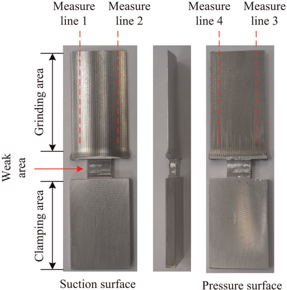
Ruled surface with a weak joint.
The suction/pressure surface is measured along two ruled lines, as shown in Figure 7. There are 20 measure points sampled for every ruled line from the top of suction/pressure surface to the bottom. Machining error is the deviation between the machined part with the designed part, which includes the dimension error, profile error and position error. The measure results in this article directly show the values of machining error. Profile error is the deviation of line or surface in the geometric shape. The value of profile error is defined as the amplitude of variation in machining errors at the measure points.
According to Figure 8, the main reason of overcut is that the diameter of CBN grinding wheel in tool path generation is less than the actual value of diameter. The machining errors are mostly fluctuant in the range of −0.065 to −0.045 mm. And the thickness at the top of this blade is greater than that at the bottom because of the deformation of blade in the grinding progress. According to the amplitude of variation in machining errors, the deflection of this blade should not exceed 0.02 mm, which proves that the deformation of this blade is sufferable, although there is a weak joint with lower rigidity.
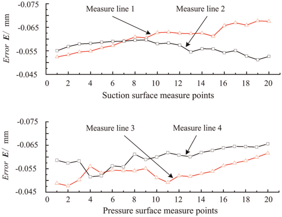
Measure results of the ruled surface.
Cantilever grinding of a blade with a three-axis machine
The length of this aero-engine blade (material: 1Cr11Ni2W2MoV) is about 49.5 mm and the maximum length of chord line is about 19.5 mm. As shown in Figure 9, this aero-engine blade is machined by the cantilever grinding process on a three-axis numerical control (NC) machine tool.
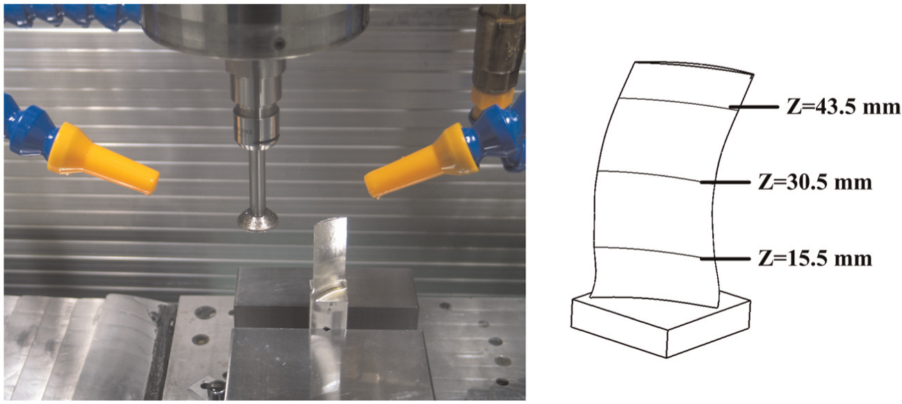
Three-axis cantilever grinding of a blade.
The sequential grinding style in section “Cantilever grinding of aero-engine blade” is used in the machining of this blade. The speed of CBN grinding wheel is 33.0 m/s and the feed rate is 1500 mm/min. And the scallop height of suction/pressure surface is within 0.005 mm.
Then the suction surface and pressure surface are measured. There are 40 measure points on every cross-sectional curve. The results are shown in Figures 10 and 11.
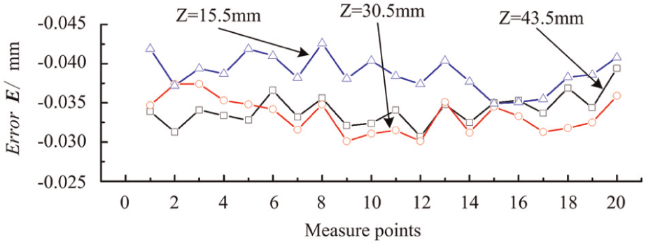
Measure results of suction surface.
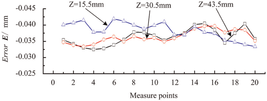
Measure results of pressure surface.
According to Figures 10 and 11, the machining errors are negative due to the diameter error of CBN grinding wheel. The machining errors of suction/pressure surface are fluctuant in the range of −0.045 to −0.030 mm. And the profile error of suction/pressure surface is within 0.02 mm. If the position of section curve Z = 15.5 mm at the bottom of blade is defined as the reference, the deflection of this blade is about 0.01 mm at the section curve Z = 43.5 mm.
The machining efficiency of this blade is good using the cantilever grinding process. And machining cost is lower due to utilizing the three-axis machine tool compared with a five-axis machine.
Cantilever grinding of a blade with a five-axis machine
Another aero-engine blade (material: 1Cr11Ni2W2MoV) is machined on a five-axis NC machine tool. The length of this blade is about 41.0 mm and the maximum width of chord line is about 44.0 mm.
The symmetrical grinding style in section “Cantilever grinding of aero-engine blade” is applied in the machining of this blade. And the machining parameters are same as in section “Cantilever grinding of a blade with a three-axis machine.” The machining errors of suction/pressure surface are measured on the coordinate measuring machine (CMM) as shown in Figure 12. There are 80 measure points on every cross-sectional curve. And the errors of four cross-sectional curves are shown in Figure 13.
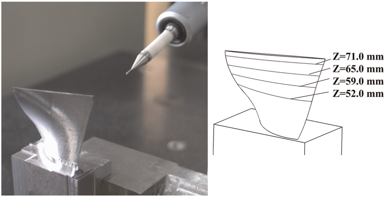
A machined aero-engine blade in measurement.
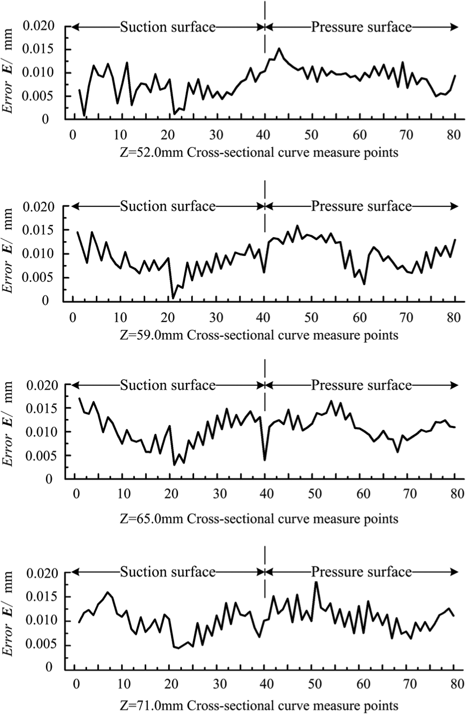
Measure results of cross-sectional curves.
According to Figure 13, the machining errors of suction/pressure surface are fluctuant in the range of 0–0.02 mm. And the profile error of suction/pressure surface is not beyond 0.02 mm. Because the maximum length of chord line is greater than the length of this blade, the rigidity is lower while the machining errors are greater at the leading/trailing edge. And the deflection of this blade is not beyond 0.01 mm at the section curve Z = 71.0 mm, while the section curve Z = 52.0 mm is the datum at the bottom of blade. So the machining errors are greater at the nearby area of leading/trailing edge.
The effectiveness of cantilever grinding process for aero-engine blade is proved by the machining results from the above four grinding examples.
Conclusion
The fixture layout for cantilever grinding is simple, which can reduce machining cost. Only one end of the blade is fixed, which could decrease the influence of fixture and avoid errors caused by the clamping force.
The magnitude of grinding force is appropriate for the machining of aero-engine blade with low deflections. The machining parameters with smaller strip width and proper grinding depth would make better grinding effectiveness under a certain grinding efficiency. The symmetrical tool path generation is better for improving the rigidity of blades in the cantilever grinding process.
The profile error of suction/pressure surface machined by the cantilever grinding process does not exceed 0.02 mm. And the leading/trailing edge with a radius of about 0.05 mm can be machined using the cantilever grinding process. The cantilever grinding process can be applied both in the three- and five-axis machining.
Footnotes
Appendix 1
Declaration of conflicting interests
The authors declare that there is no conflict of interest.
Funding
This study was partially supported by the National Natural Science Foundation of China (grant number 51105024) and the National Science and Technology Major Project (grant number 2013ZX04001051).