
Abstract
It is estimated that the industrial sector is responsible for 29% of the United States’ greenhouse gas emissions. Recent efforts have sought to reduce the carbon footprint of manufacturing activities. Research suggests that a key to further reducing industrial-based greenhouse gas emissions is to more accurately characterize the carbon footprint of manufacturing processes. Life cycle assessment is a powerful tool that can be utilized to characterize the life cycle environmental impacts of a process. Current life cycle inventory databases that are used in life cycle assessments only have limited coverage on manufacturing operations. This article develops a parameterized process model for computer numerical control grinding, which enables the calculation of life cycle inventory data in a relatively rapid fashion and has some substantial characteristics, such as transparency, engineering quality, and the ability to reflect changes when new information is secured. Surface grinding of cobalt–chromium alloy knee implants is used as a case study to demonstrate the approach.
Keywords
Introduction
As world population grows and standard of living improves, more and more manufactured goods are expected to be consumed, either directly or to provide services. As a result, manufacturing will maintain its key status in modern economies, and continue serving as a valuable contributor to wealth generation and job creation, especially in developing countries. However, manufacturing activities have significant impacts on the environment and the ecological systems. Of particular concern are issues related to greenhouse gas emissions and climate change. It has been estimated that the industrial sector alone is responsible for 29% of the greenhouse gas emissions in the United States, 1 out of which manufacturing activities are dominating, i.e. about 84% of energy-related carbon dioxide emissions and 90% of the energy consumption.
Growing environmental concerns, coupled with public pressure and stricter regulations, have pushed manufacturing enterprises to become environmentally responsible. Particularly, recent efforts by national governments and agencies have sought to reduce and control carbon footprint by focusing on manufacturing activities.2,3 One such manufacturing process of interest is grinding. Grinding is a critical process to achieve high surface quality and dimensional precision, especially for hard-to-machine materials. The grinding industry accounts for a significant portion of manufacturing activities worldwide. Global Industry Analysts estimate that the global grinding machine market will reach $3.19 billion by the year 2015. 4 Given grinding processes’ important role in modern manufacturing, environmental issues associated with grinding processes are gaining attention in both academia and industry.
Research suggests that a starting point for efforts to reduce manufacturing environmental footprints is to more accurately characterize the environmental impacts of manufacturing processes.5,6 One of the most commonly used methods for characterizing the environmental profile of a process is life cycle assessment (LCA). A manufacturing process has inputs in the forms of materials and energy while delivering products and producing emissions and wastes. The materials and energy consumed are, in general, manufactured “goods” that have their own environmental impacts. LCA takes a holistic approach and includes all direct and indirect environmental impacts, thus provides a comprehensive and accurate view of the environmental profile of a process. 7 To date there have been LCA studies on a variety of manufacturing processes.8,9 However, to the best of our knowledge, no LCA has been conducted for grinding processes. In the past, grinding research has been focused on surface quality, wheel life, productivity, and cost, with environmental issues discussed being limited to electricity consumption, grinding fluids, and occupational health.10–14
Grinding is a complex manufacturing process and involves many interdependent process parameters. Compared with other cutting processes, during grinding the actual material removal is done by abrasive grains on the grinding wheels, which serve as many single-point cutting edges. This makes it impossible to describe the process and assess the environmental impacts simply based on theoretical models. In this article, we will present a general analysis approach for evaluating the life cycle environmental impacts of grinding processes following the, so-called, unit process life cycle inventory (uplci) methodology. 6 The approach is then demonstrated using non-cylindrical computer numerical control (CNC) grinding of an orthopedic implant.
Methodology
According to ISO 14040 series standard, an LCA study should be conducted in a four-step sequence, namely: 15 the goal and scope definition, inventory analysis, impact assessment, and interpretation. Of these four steps, the inventory analysis phase is often seen as the most crucial, as the accuracy of any analysis will depend on the quantity and quality of inventory data. To date, available life cycle inventory (LCI) databases only have limited coverage on manufacturing processes. In addition, available manufacturing datasets only provide representative/average results and ignore the effects of process parameters. Recently, researchers in the European Union and US have initiated an effort to develop a LCI database for all the manufacturing processes. The uplci project is to “produce an engineering rule-of-practice-based analysis of separate unit processes used in manufacturing and from this to create a mechanism to evaluate the life cycle inventory of manufactured products.” Each uplci provides models/equations that can be used to characterize the energy/material requirements and wastes/emissions given different operating parameters. Compared with traditional LCI datasets, uplci can be easily customized by manufacturing enterprises to more accurately estimate environmental footprints of manufacturing processes in their facilities. In this section, the uplci approach will be applied to the inventory analysis phase of the LCA study on grinding processes. Focus here is put on CNC grinding, which is widely used in manufacturing of camshafts, turbine blades, and medical devices.
CNC grinding uses abrasive cutting wheels spinning at high velocities to remove material. Tolerance capabilities for CNC grinding processes vary widely based on the type of grinding being performed, the material being ground, cutting wheel parameters, and operational parameters. A CNC grinding machine consists of a grinding wheel(s), fluid handling system, computer(s), spindle motor(s), robotic controls, and various types of auxiliary equipment. The type and size of equipment will vary according to the needs of the manufacturers. A more complete description of the types of grinders and grinding wheels can be found in Marinescu et al. 16 Figure 1 shows the material/energy inputs and outputs of a typical CNC grinding process.
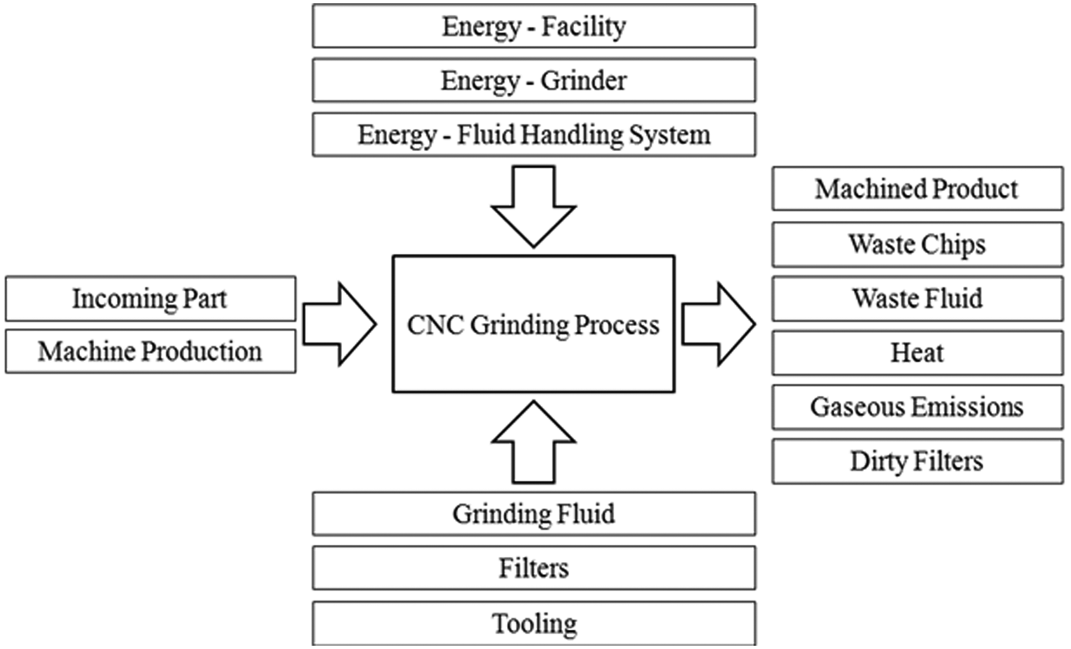
The material/energy inputs and outputs of a CNC grinding process.
Energy/electricity consumption
The required energy for a CNC grinding process can be generally formulated using the following equation (1) (adapted from Overcash et al. 6 )

where Etotal is the total energy consumed by the CNC grinding process; Etip is the energy consumed to remove the material; Ebasic is the “basic” energy consumed when loading/unloading, positioning, and securing a new workpiece onto the machine; Eidle is the “idle” energy consumed by auxiliary equipment, such as the computer and filtration system, when there is no activities performed on the machine; Efacility is the energy consumed in order to maintain a proper environment for the process; and Erecovered is the useful energy that can be recovered from the process (e.g. waste heat recovery). The concepts of tip, idle, and basic energy can be understood through Figure 2, which shows a conceptual power study, with highlighted areas corresponding to the tip, idle, and basic energies of a typical grinding process.
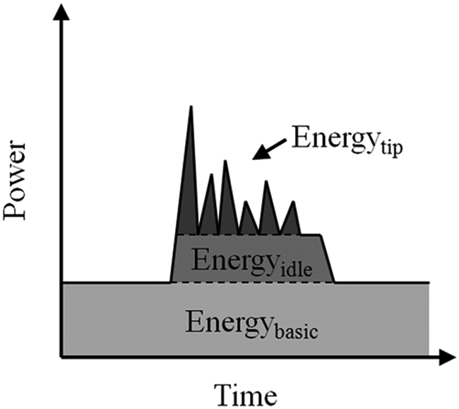
The tip, idle, and basic energies of a typical grinding process.
To determine Etip, the following equation can be used

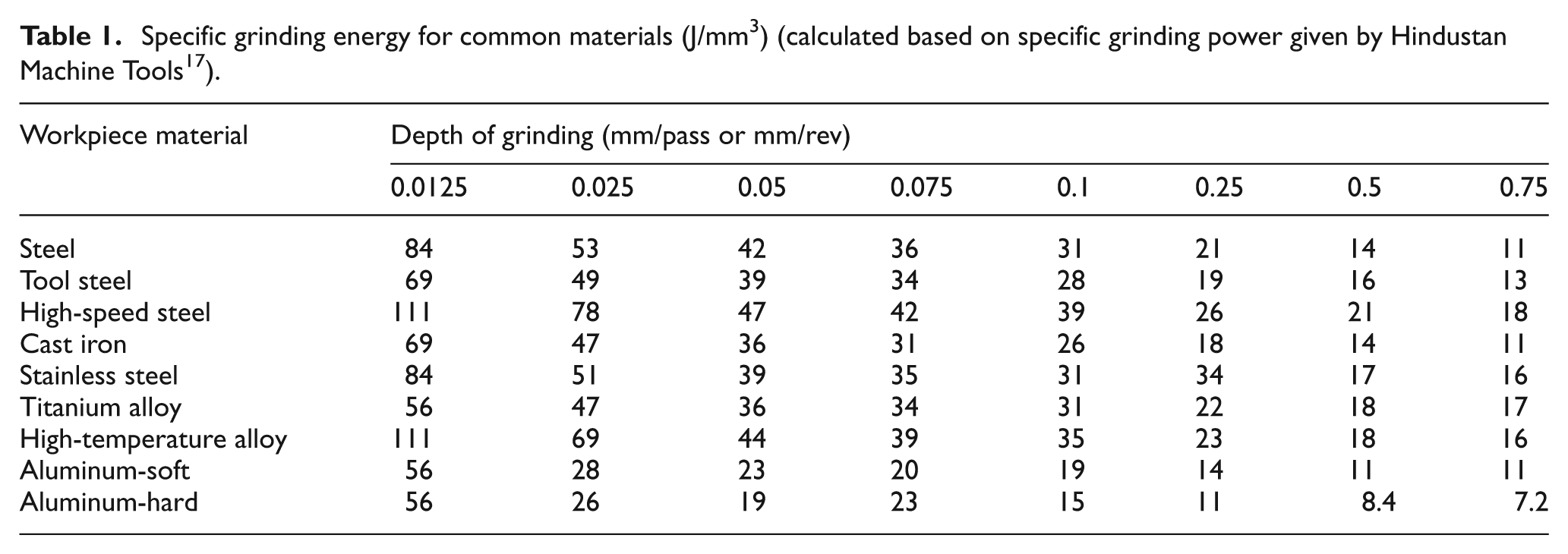
where Up is the specific grinding energy in J/mm3, MRR is the material removal rate in mm3/s, tg is the actual grinding time in seconds, and MR is the total volume of material removed in mm3. Apparently MR can be calculated given total depth of grinding and the surface area needs grinding. For specific grinding energy, Table 1 shows representative values of some common materials. It should be noted that specific grinding energy is mainly a function of workpiece material and the average cross section area of chips (which is largely determined by depth of grinding in mm/pass or mm/rev). Other parameters, such as sharpness of wheel, wheel speed, and grinding width, may also have some effects on specific grinding energy, but these effects are usually smaller.
Specific grinding energy for common materials (J/mm3) (calculated based on specific grinding power given by Hindustan Machine Tools 17 ).
Most modern CNC machines have very low power consumption while loading/unloading workpieces, typically in the range of 0.5–1 kW. In a high throughput or mass production environment, the basic energy consumption is small. However, this is not the case for idle energy. A significant amount of heat is generated during the grinding process, requiring coolant to be provided at a high flow rate. It is common to see a large coolant delivery pump attached to a CNC grinder. For a grinder with a rated spindle power of 20 kW, the coolant delivery pump could have a power rating at 5–10 kW. In addition, it is a common practice to supply coolant at a rate required for maximum load during a grinding operation.
Efacility is also referred to as non-process energy. Usually data is only available for the entire facility and how to allocate total energy consumption to each process presents a challenge. As pointed out by Bawaneh et al., 18 non-process energy consumption is not well correlated with physical dimensions of a facility, desired comfort level, and climate zone characteristics. Non-process energy consumption and process energy are likely closely coupled, but the relationship between the two is a topic under further investigation.
Grinding wheel
Various types of grinding wheels are available for CNC grinding processes. Often, grinding wheels are made of high-speed steel and coated with abrasive particles. Coatings for the removal of material with high hardness include diamond, synthetic diamond, and cubic boron nitride (cBN). These abrasive materials come in different grit sizes and concentrations and are applied to the wheel with resin bonds, electroplating, or other means. Of particular interest is the use of cBN as an abrasive coated onto grinding wheels, as it represents an increasingly significant portion of grinding wheels used in CNC grinding processes. In industrial applications, the grinding wheel is often used until the coatings become less effective, or start to produce tolerance errors on the part. The wheel is then sent to be recoated or recycled. The abrasive coatings of the wheel are of interest in LCAs owing to the high amount of embodied energy in the particles, such as cBN, in the coatings.
Grinding fluids
Grinding fluids are critical for safety measures in grinding. The high heat generated by the material removal at high speeds can cause certain materials to combust. Thus, flood cooling is often used in grinding applications to provide safe removal of material. This is significant because flood cooling consumes a high amount of energy. Flow rates of grinding fluid will vary from application to application.
Grinding fluids are often oil based, with one part oil mixed with 40 to 50 parts water. In some cases mineral oil or gas-based cooling is used. Filters, usually paper-based are used to clean the grinding fluid so that it is suitable for reuse. The replacement rate of the filter will depend on the type of filter and the application for which it is used.
Wastes
The waste mass of the process can be calculated with the following equation

where, for n types of materials, mw,k is the waste mass of the kth type of material, mo,k is the output mass of the process for the kth type of material, and mi,k is the input mass of the process for the kth type of material. Types of waste mass include dirty filters, chips, waste grinding fluid, and used tools. The amount of chips generated can be calculated based on total volume of material removal and workpiece density. For other types of wastes, life span information has to be collected in order to allocate consumption of supplies and tools to each part.
Case study
In this section, a case study is presented for a LCA of a non-cylindrical CNC grinding process. The case study will be presented in the four steps of LCA.
Goal and scope
The goal of the study is to characterize the environmental impacts for CNC grinding. This analysis will aid product designers and manufacturers as they seek to understand the environmental impacts of CNC grinding. Also, analysis will show potential areas for improvement to reduce the environmental impact of grinding. The functional unit used for this study is the grinding of 5000 orthopedic knee implants. A conceptual model of the knee implant is shown in Figure 3. The scope of the study is confined to the mass and energy flows of the CNC non-cylindrical grinding process.
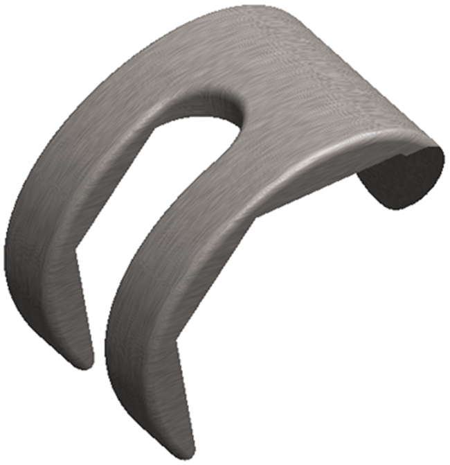
Conceptual model of a knee implant.
In an attempt to capture a more accurate view of the potential environmental impacts of the CNC grinding process in the case study, efforts were made to include all of the energy and mass flows affected by the process. It should be noted that the material production, machine production, pre-grinding processes, and post grinding process were not included in the system boundaries owing to the fact that the focus of the study is on the actual grinding process itself.
The CNC grinding machine used for the case study is a Huffman HS-155R Multi-Axis Superabrasive Grinding System (Huffman Corporation, Clover, SC, USA). This system has a 20.9 kW (28 hp) spindle motor, five-axis configuration, computer, and two cBN-plated stainless steel grinding wheels. A fluid handling system is attached to the grinding system and has an 11.2 kW (15 hp) pump used to distribute the coolant during grinding operations, two 0.37 kW (1/2 hp) pumps to continuously circulate the grinding fluid for filtration, and a 0.745 kW (1 hp) pump for collecting and filtering mist in the grinding chamber.
LCI
Simapro 7.1 and the Ecoinvent 2.0 database are used to develop the LCI. Data gathered for the LCI was based on direct measurements, interviews with manufacturing engineers responsible for the process, machine operators, and maintenance workers. The grinding process in the case study consists of two basic operations: the material removal operation and the grinding coolant distribution and filtration operation.
The material of the implant is a cobalt–chromium alloy. Prior to the grinding operation, the general shape of the implant is formed using sand casting. Material is removed from the implant through three different runs of the grinding wheel in the same path, with an initial run of 0.762 mm (0.03 in) followed by removing 0.381 mm (0.015 in), and a third run of variable depth depending on the dimensions of the casted part. Usually the third run is 0.254 mm (0.01 in). Two implants are ground at the same time using the grinder’s dual wheel configuration.
The grinding wheels used for the process are 20.32 cm (8 in) diameter by 0.95 cm (3/8 in) wide and made of high-speed steel. The wheels are coated with cBN, a synthetic material with high hardness and relatively low wear in the grinding processes. The manufacturing process of cBN was used to derive data for the LCI owing to the absence of the cBN manufacturing process in the Ecoinvent 2.0 database. cBN is synthesized through the following chemical reaction at temperatures of between 1800 °C and 2700 °C, and pressures of 50 to 90 kbar

The mixture is then purified using acid to dissolve unwanted residues of the reaction. The cBN is then coated onto the desired surface. 13 In this case, the cBN is mixed with a phenol resin and hot pressed onto the wheel with a thickness of 1.27 mm (0.05 in). The grit classification is 80 (10,000 particles/carat) and the concentration of cBN is 100 (24% volume). 13 A plating of nickel is applied to the cBN-coated wheels to improve wheel life and performance. The process for the manufacturing of boron carbide is listed in the Ecoinvent 2.0 database and was modified according to the above conditions for the manufacturing of cBN. The process of converting hex boron nitride (hBN) to cBN is reported to be similar to the high-pressure high-temperature methods used to convert graphite to synthetic diamonds. 19 Data taken from Ali 19 suggests that 20 kWh of energy is required to produce one carat (0.2 g) of synthetic diamond. The mass of cBN and phenol resin applied to the wheel was calculated using the volume and density of the material.
The wheels are sent back to the manufacturer where they strip the nickel-coated cBN from the stainless steel grinding wheel with acid etching, and then re-plate it with a new coat of cBN and nickel. This process occurs after the manufacturing of 5000 parts and is performed, on average, eleven times before re-plating is no longer a viable option and a new wheel is needed as the used wheel is recycled.
The spindle used to rotate the grinding wheels runs on a 20.9 kW (28 hp) motor. The spindle is rotated at approximately 8000 r/min during the material removal operation. Measuring of the mass of the implant, both before and after the grinding process, was performed to determine the amount of MR. The average mass of MR for each part was found to be 0.05 kg. Thus, a total of 250 kg of chips are processed for every 5000 parts produced.
Paper filters and polypropylene bag filters are used to separate the coolant from the scrap metal. The used filters are sent to a metals recycling facility, where the scrap cobalt–chromium alloy is separated from the paper filters and recycled.
An oil-based fluid is used as the grinding fluid for the grinding process. A material safety data sheet (MSDS) was obtained for the fluid that identified the composition of material to be petroleum distillates, solvent refined heavy paraffinic. No toxicity was reported in the MSDS. The entry for lubricating oil in the Ecoinvent 2.0 database was used as its characteristics matched closely with the information provided by the MSDS for the grinding fluid. It was reported that 208 l (55 gallons) of the grinding fluid was replenished during a period of 3 months. This equates to 90 l (24 gallons) of grinding fluid replenished for every 5000 parts. Grinding fluid is filtered and re-used by the grinding system. However, the replenishing of fluid supplies is necessitated by losses caused by leaks, and also oil particles that escape into the atmosphere. The oil that is collected is recycled by a local company. The environmental and health impacts of oil particles in the air are not included in this study owing to scope restraints. Additional information on oil particulates in the air can be found in Sutherland et al. 20 and Simpson et al. 21
The energy used by the grinding system was measured using a Fluke 1735 power logger (Fluke Corporation, Everett, WA, USA). Average active power was recorded in 0.5 s intervals for the filtration system, the main power of the grinding machine, the servos used to control the movement of the fixture and grinding wheel, and the spindle motor. In the case of the spindle motor and grinding fluid distribution and filtration system, power studies were conducted using two power loggers simultaneously, with power studies of the main power of the grinding machine to ascertain the amount of power used by different systems in the grinding process.
The energy used by the grinding process can be divided into four categories: cutting energy, coolant distribution and filtration energy, other auxiliary equipment energy, and idle energy. Cutting energy is defined by the amount of energy used by the spindle motor during material removal operations. The grinding fluid distribution and filtration energy is the energy used by the pumps and mist collector. Other auxiliary energy is the energy used by equipment, such as servos, computers, emergency fire extinguishing systems, and lighting in the grinding machine.
Through multiple power studies, it was found that the power used by the spindle motor was the only piece of equipment that significantly altered the total power consumption of the grinding process. This variation in required power can be attributed to slight variations in cycle time (change in removal rate) and the variation of MR caused by the tolerance variations of the casting process. The filtration system and other auxiliary equipment seemed to consume energy at a rate independent of the amount of material being removed, but varied slightly according to the cycle time. Figures 4–6 show the power profiles for the collective CNC grinding process, the spindle motor on the CNC grinder, and fluid handling system respectively.
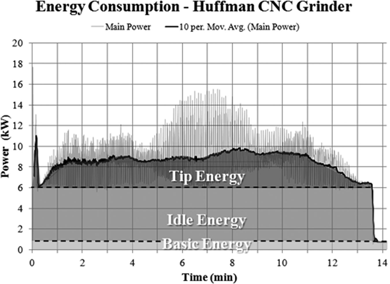
Power consumption of the grinding machine.
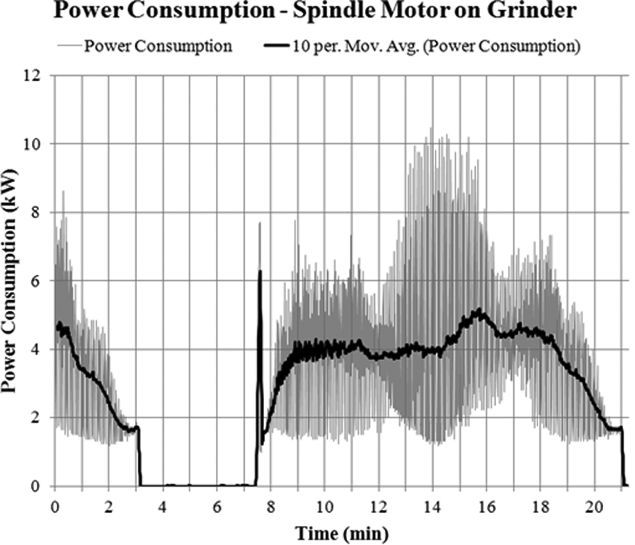
Power consumption of the spindle motor.
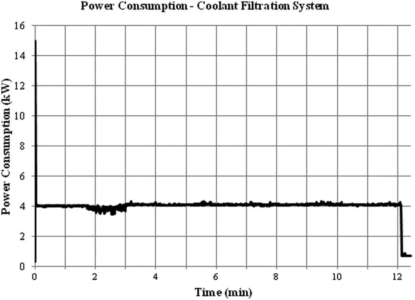
Power consumption of the fluid handling system.
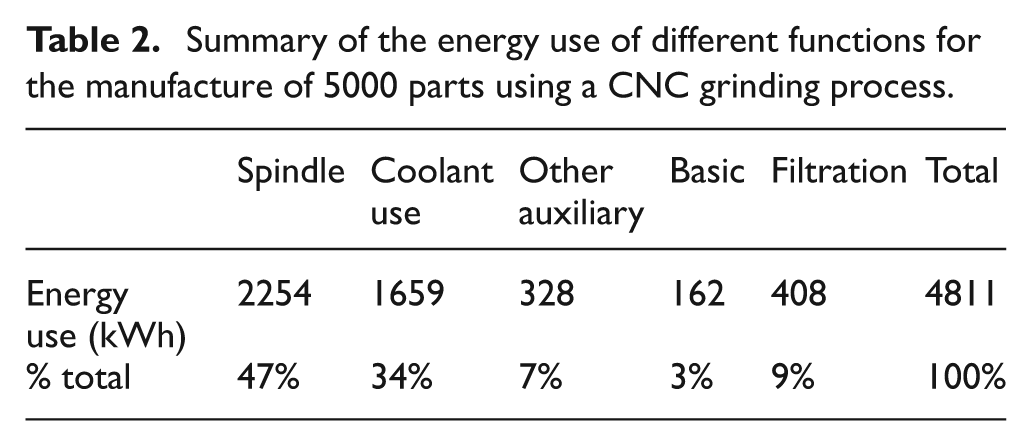
The energy consumed over 5000 parts for the spindle motor, grinding fluid distribution and filtration, other auxiliary equipment, and idle periods, was calculated using a combination of power studies and production data. The entry for the average electricity production and distribution in the US was used in the Ecoinvent database. The energy data is summarized in Table 2.
Summary of the energy use of different functions for the manufacture of 5000 parts using a CNC grinding process.
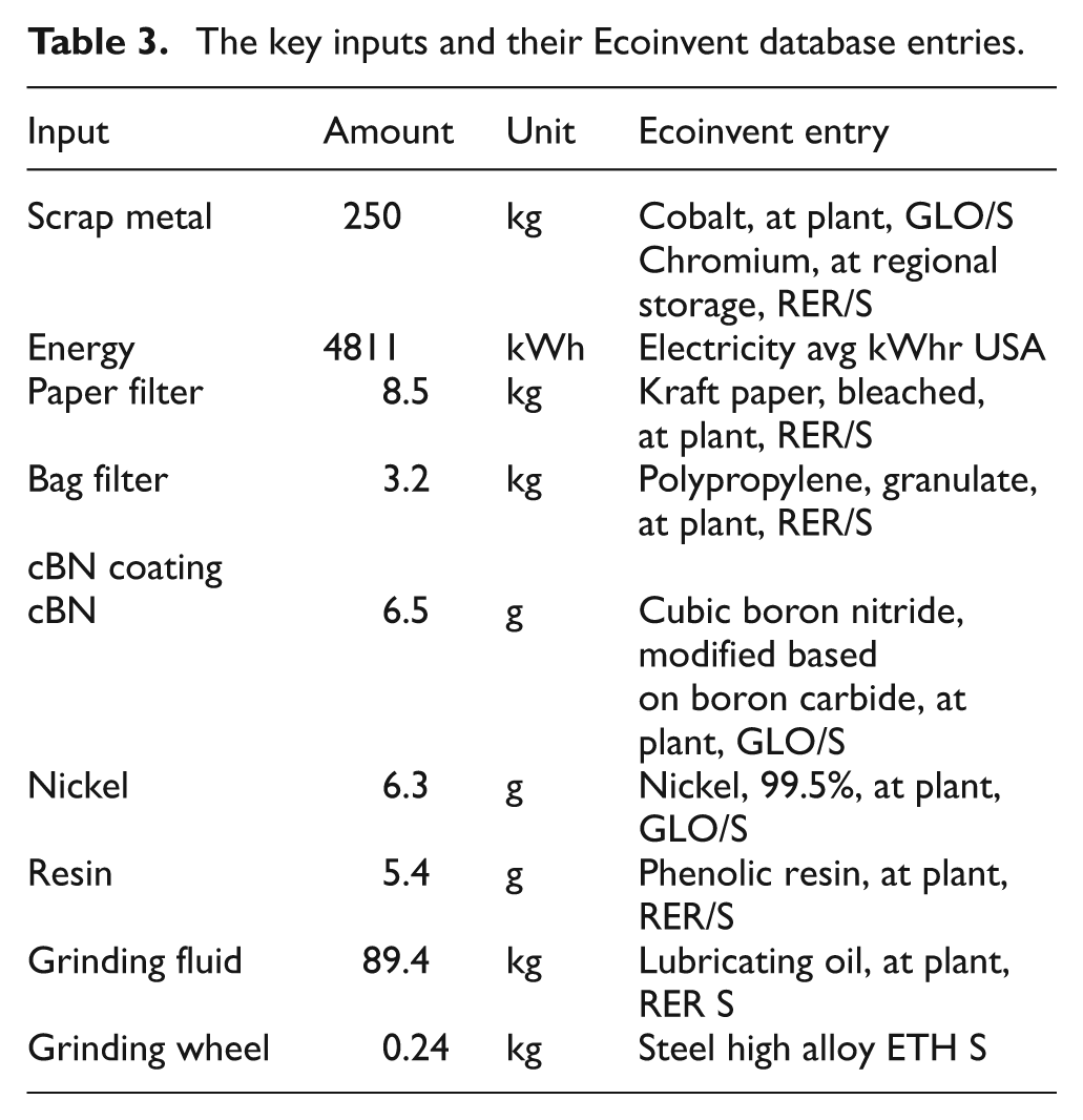
A summary of the key inputs and their entries used from the Ecoinvent database are listed in Table 3.
The key inputs and their Ecoinvent database entries.
Impact assessment
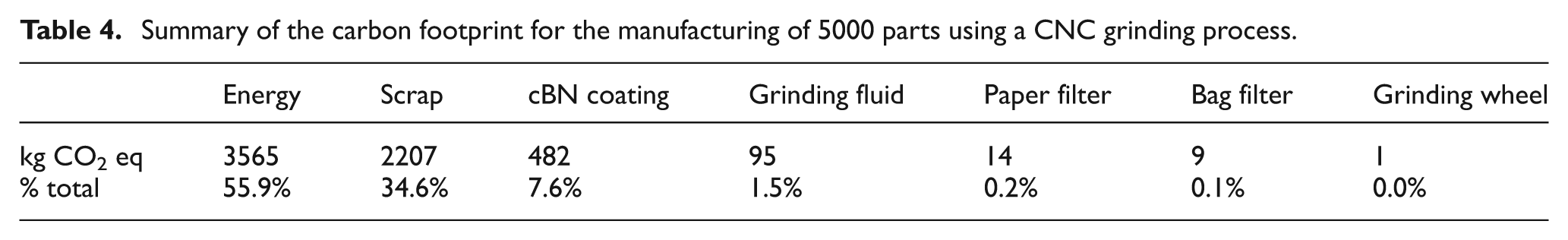
Impact assessment was carried out in SimaPro 7.1 through the use of the TRACI 2.0 method developed by the US EPA. As was previously mentioned in the goal and scope definition phase, the carbon footprint of the CNC grinding process is of most interest among other environmental impacts. The carbon footprint of the different functions is shown in Table 4 in units of kg of carbon dioxide equivalent per 5000 parts manufactured (kg eCO2). Table 4 also shows the percentage contribution of different functions for the CNC grinding process to the overall carbon footprint of the process.
Summary of the carbon footprint for the manufacturing of 5000 parts using a CNC grinding process.
Interpretation
An analysis of the contributions to the overall carbon footprint of the process reveals that three functions account for almost all (98.1%) of the carbon footprint of CNC grinding: energy use in the form of input electricity (55.9%), scrap production (34.6%), and the cBN coating on the grinding wheel (7.6%). On the other hand, grinding fluid, filter use, and the steel grinding wheel have very little impact on the overall carbon footprint.
As was mentioned earlier, energy consumption of grinding technologies has only recently been considered a critical need in manufacturing owing to the larger relative costs of tooling, labor, and materials. Owing to the dominant contribution of energy use to the carbon footprint in the grinding process, increasing the energy efficiency of CNC grinding processes could potentially do more than any other measure to reduce the carbon footprint of the grinding process in a sustainable manner. It should also be pointed out that, as shown in Table 4, energy consumption owing to circulating and filtering grinding fluids accounts for about one-third of total energy consumption. This suggests that better fluid handling and delivering systems could significantly reduce energy consumption. There have been studies on optimizing coolant flow rate and nozzle set-up to minimize usage.22,23 In addition, minimum quantity lubrication (MQL) has been explored as an alternative fluid application method for many machining operations including grinding. 24 However, to date, the actual application of MQL to the CNC grinding process has been very limited, mainly owing to high initial cost, lacking technical expertise, and fire hazard concerns.
Till now, energy consumption (proportional to carbon footprint) only accounts for a very small percentage of process costs. Efforts to minimize the carbon footprint (for example by reducing grinding fluid flow rate) may not lead to considerable cost savings. However, efforts (through design or process planning) that lead to less scrap generation will reduce both the carbon footprint and cost associated with the process. Owing to the mounting concerns on global warming, policy measures may be introduced, e.g. carbon tax and cap-and-trade, which will likely increase cost associated with energy consumption. As a result, manufacturing enterprises may become more motivated to reduce their carbon footprints as a means to reduce operation costs.
Conclusions and future work
The grinding process is an important manufacturing process to modern industry. Significant concerns have grown with regard to the sustainability of grinding processes. This article presents a general method for characterizing environmental impacts of a grinding process using LCA methodology. The method follows uplci methodology, a parameterized modeling approach that enables fast LCI development for varying operating conditions. To demonstrate the approach, carbon footprints associated with surface grinding of cobalt–chromium alloy implants is used as a case study. It is found that process energy consumption dominates, with half consumed by the spindle and one-third consumed by pumps used for grinding fluid handling. Owing to the large amount of energy consumed during grinding wheel manufacturing, the carbon footprint owing to the wear of the grinding wheel is also considerable.
Footnotes
Funding
The authors would like to recognize Biomet Inc. for the funding of this study as part of a carbon footprint reduction project.