
Abstract
The fierce competition in the global manufacturing environment is forcing enterprises to seek competitiveness beyond traditional aspects such as functions, quality, cost, and lead time. An emerging strategy is to develop sustainable manufacturing systems. An ideal sustainable system has the characteristics of remanufacturing, redesigning, recovering, reusing, recycling, and reducing. However, this type of sustainability mainly refers to the products rather than to the manufacturing system itself. When the design and operation of a manufacturing system are concerned, the criterion of sustainability often conflicts with other requirements such as cost and lead time. Instead of establishing a total new system paradigm, it is more realistic that the concept of sustainable manufacturing is used as a guidance to evolve existing systems to an advanced level. In this article, a case study is introduced to recycle an obsolete test machine to meet new functional requirements; it has shown a significant economic benefit. The presented case study provides a new perspective of economically evolving dedicated machines or manufacturing systems into sustainable systems.
Keywords
Introduction
With the rapid development of technology, global manufacturing capacity is abundant in contrast to customers’ needs; customers demand products not only for more functions, higher quality, and faster delivery time but also at a lower cost.1–3 In addition, the batch volume for the same product is reduced and the product life cycles are shortened. This brings a critical requirement of manufacturing resources: machines and tools in a system should be reconfigurable, so that they can be reconfigured to accommodate new requirements as time goes by. 4 Changes and uncertainties can only be dealt with by changes. Flexible or modular systems provide a vital solution for the next-generation systems.5–10 However, making a system flexible or modular unavoidably increases the initial costs of system development. In most cases, it prevents customers from a direct adoption. It is then not surprising to see that the majority of existing manufacturing systems are dedicated to a limited number of product variants.
How to achieve sustainability of a manufacturing system has been studied by many researchers. For example, Srai et al. 11 emphasized that it was important to quantify system wastes and developed a process maturity model to evaluate the carbon foot printing along a supply chain. In the case when a system or machine tool becomes obsolete, which is failure to meet the new requirement of production, it is suggested to look into the possibility of remanufacturing, redesigning, recovering, reusing, recycling, and reducing (6R) existing resources; before a final resolution, the system or machine tool is completely replaced by new manufacturing resources. Bear in mind that if it is not the primary interests of a machine manufacturer, it is unfair to obtain the support from original equipment manufacturer (OEM). However, it might bring a significant economic benefit to system users. We have found no case reduce, reuse, and recycle (3R), redesign, reduce, reuse, and recycle (4R), or redesign, reduce, reuse, recover, recycle, and remanufacture (6R).
In this article, the requirements of system reconfiguration will be examined from a new perspective: instead of developing a new reconfigurable system based on modular architecture, the system reconfiguration can be achieved based on 6R. The feasibility of such a strategy has been validated via a case study. The rest of article is organized as follows. In section “Strategies to deal with changes and uncertainties,” the strategies to deal with changes and uncertainties are discussed. The challenges involved in developing reconfigurable manufacturing systems are identified, and potentials of applying 6R to achieve the system adaptability are proposed. In section “Overview of case study,” the problem statement of the case study is defined, the demanding requirements are quantified, and design options to meet the new requirements are discussed. In section “Reconfiguration of test machine,” the optimal design is selected and materialized; the mathematic models and simulations are developed to optimize the machine structure. Moreover, the machine prototype is developed and operated to validate the performance of reconfigured test system. In section “Summary,” the presented work is summarized; the advantages and challenges of system reconfigurations based on 6R are explored.
Strategies to deal with changes and uncertainties
The requirements of modern manufacturing systems have been investigated by many researchers, and the strategies to cope with these requirements have been extensively discussed in the literatures.12–15 To achieve a sustainable manufacturing system, Thomas 16 indicated that technological innovations were the most important factors to improve the sustainability of small or medium companies. Griffiths 17 discussed the evolution of manufacturing paradigms along with the change in manufacturing environment extensively, and it was suggested to establish the standards for key technological enablers. De Coster et al. 18 investigated the business planning and performance implications to implement the development strategies of sustainable products. Yan et al. 19 proposed a sustainability-oriented approach to support the modularization of products. Baumers et al. 20 studied the sustainability of additive manufacturing processes, and they developed an energy consumption model to measure energy efficiency. Ball et al. 21 argued that it was important to integrate the flows of materials, energy, and wastes to achieve green manufacturing, and they discussed some enabling technologies could be applied for such integration. Dong et al. 22 emphasized the importance of recycling to the system sustainability; they studied the sequence planning in disassembles based on part accessibility for recycling of products.
In this section, the strategies to deal with changes and uncertainties in a sustainable manufacturing system are focused. Note that changes and uncertainties relate to many factors such as shortened product cycles, reduced batch volume of products, turbulent dynamic environments, and unavoidable trending toward a buyer’s market. It becomes essential for enterprises to make new products in a timely manner when customers’ requirements are changed or their business environments are altered due to uncertainties and dynamics.
Changes can only be coped with by changes. For manufacturing systems, two fundamental strategies to make system adaptable are flexible systems and modular systems. Flexible systems, such as a flexible fixturing system or a flexible manufacturing system, have a set of flexible components whose behaviors can be adjusted by control systems to meet new requirements. Modular systems, such as modular robotic systems, are usually developed upon modular architecture with different types of modules; by selecting different types and number of modules and assembling them in different topologies, many system configurations can be formed to fulfill different tasks. The adaptability of a flexible system is generally confined by the number of components and the complexity an integrated system can possess, while the adaptability of modular system can be theoretically expanded infinitely without the consideration of other factors. Moreover, these two strategies can be integrated to achieve a high level of system adaptability. 23
As shown in Figure 1, changes and uncertainties are spanned in the time domain. To deal with all possible changes and uncertainties over the life cycle of a manufacturing system, a physical flexible system or modular system must include all flexible components or modules for any possible requirements. While the system is required to be adaptable, design and implementation of such a physical system bring up new issues such as the challenge of predicating future customers’ needs; huge initial investment; the complexity of planning, scheduling, and maintenance; and high investment risk. On the other hand, if the flexibility and modularity are achieved by virtual enterprise or enterprise alliance, changes and uncertainties can be addressed by a temperate system, which can relieve the burden of possessing all requirement hardware within an individual enterprise; different temperate systems can be dynamically formed to fulfill new functions. However, the issues related to retired components have not been addressed. In this article, a third strategy is proposed, that is, obsolete manufacturing resources are assessed to see whether they can be reused, recycled, redesigned, and recovered to fulfill new functions. Readers should note that the proposed strategy is not a universal solution; however, for many enterprises who are experiencing a shift of a production line, it is strongly suggested to look into this option. The case study in sequential sections has shown that an appropriate application of this strategy can bring significant economic benefit to an enterprise and make our living environment more sustainable.
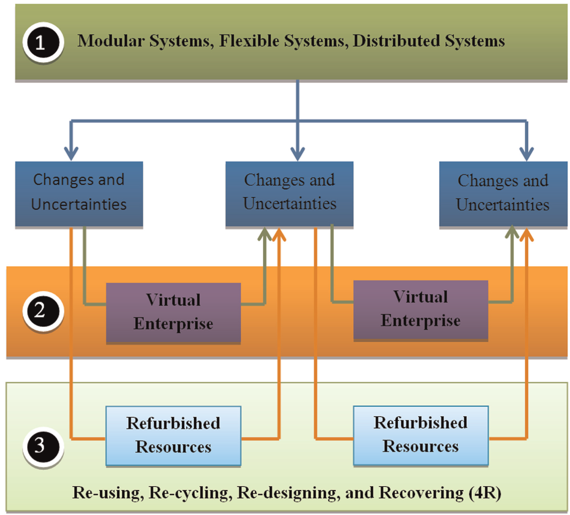
4R is the third strategy to deal with changes and uncertainties.
Overview of case study
Our client is one of the leading companies in carbon steel production and metal recycling. It provides a wide range of steel products such as beams, bars, and metal sheets. In 2010, the client entered the market for standard-strength railway rail after certified by America’s Class I railroads. The standard rail length size is 72.152 m, but the company can also provide rails in longer or short lengths such as 11.887, 12.192, or 24.384 m. Rails can be welded together to create long rail strings, which are called continuously welded rail (CWR) strings with lengths that can reach 502.92 m. The general process of rail-making is shown in Figure 2.
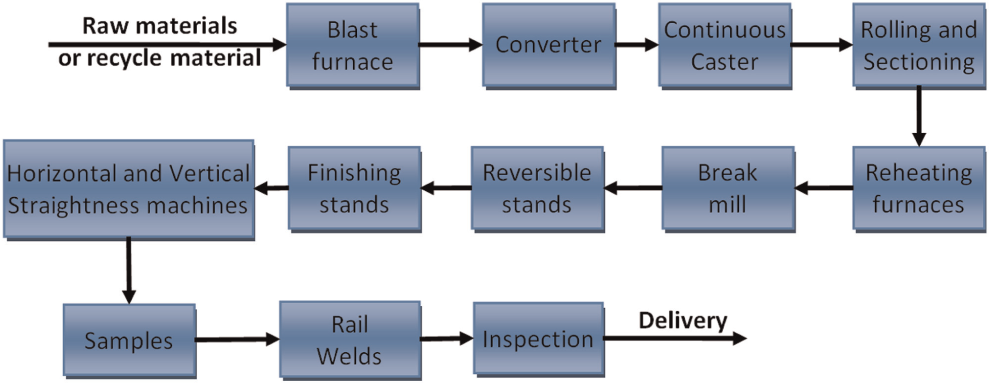
General process of steel-making products.
It is seen from Figure 3 that a rail bend test machine is required to test welded rails. Possible defects of welds have been discussed by Eklund and Crocker, 25 and the tests related to welds are hardness test, welds test, fatigue test, and bend test. 26 This article focuses on the bend test machine; this test is performed at the collar edge of aluminothermic welds to verify whether the strength and stiffness are sufficient to endure the required load within the specified deflection and identify the failure models occurring under a transverse load condition. The failure mode is determined when a specimen is finally broken as it is overloaded continually. Figure 3 has illustrated the current test system; its main components include controller, test monitor, oil reservoir, pipe system, cylinder, frame, and the sensors such as a displacement sensor and the workcell. A rail sample and its dimensions are shown in Figure 4. Its dimensions are standardized as 1.2192 m in length with the welds in the middle. The press has two ends with a distance of 0.304 m. The transverse force is applied on the press to see whether the rail can endure the specified load within the limit of deformation.
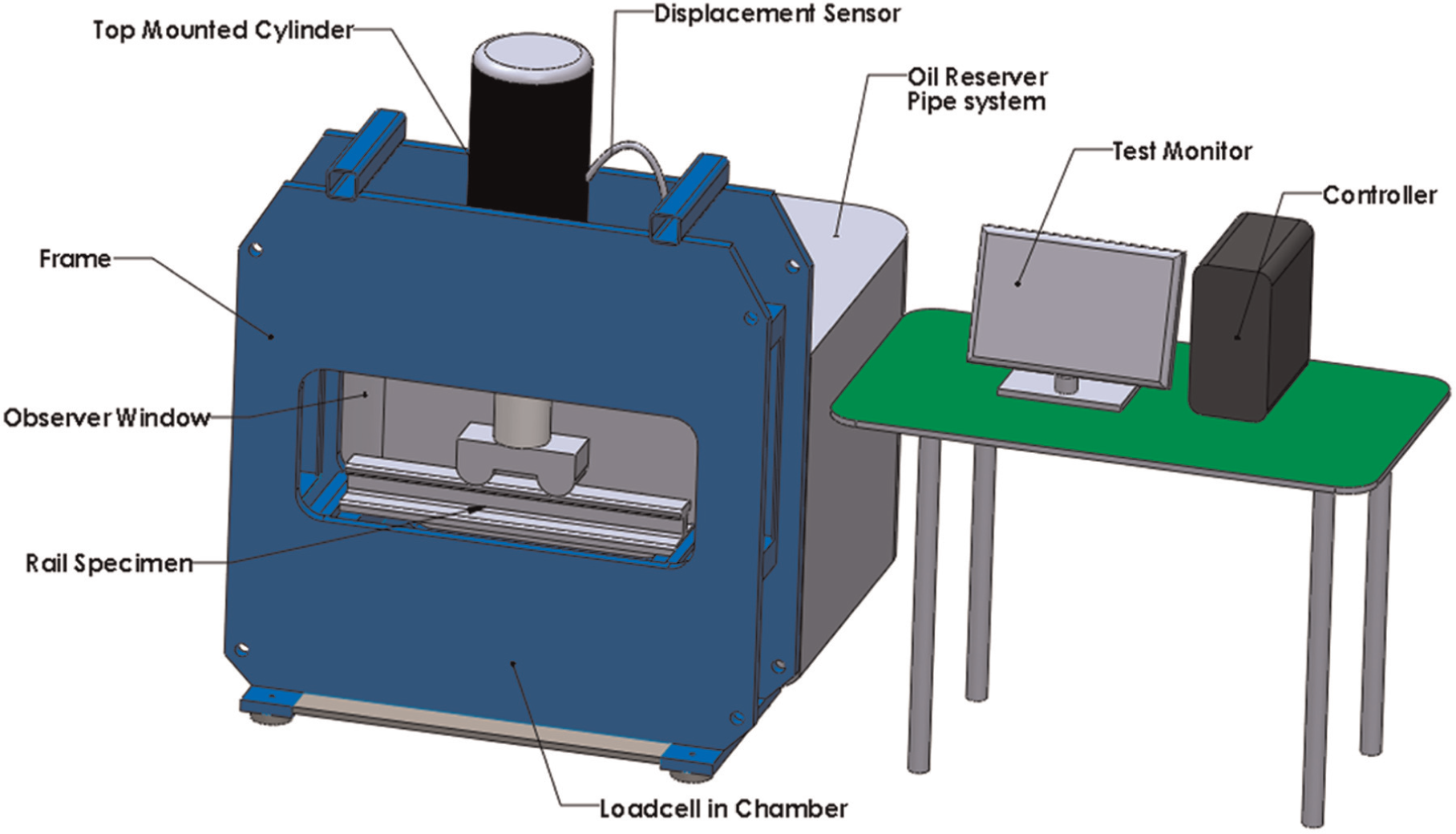
Configuration of existing bend test machine.
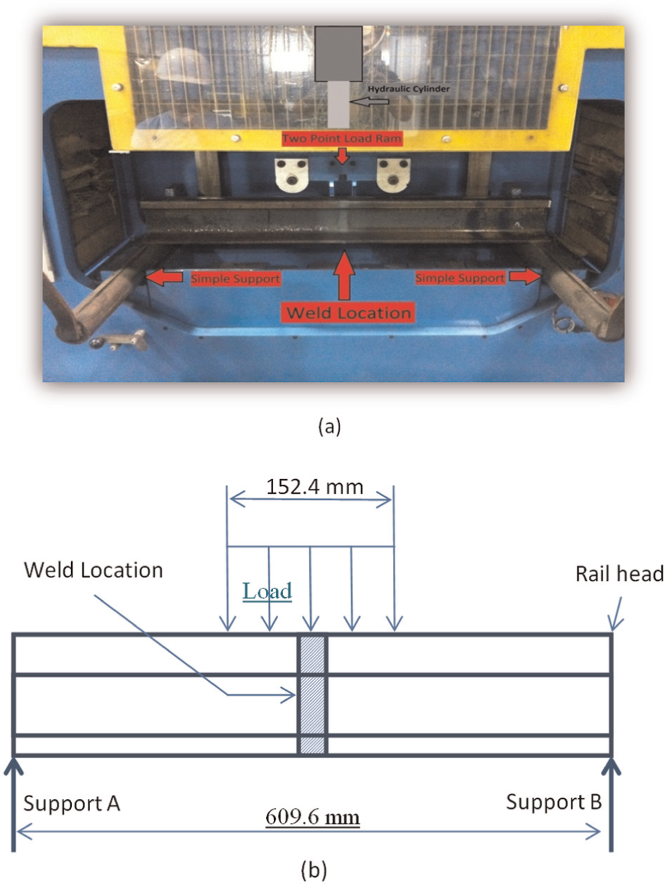
Standardized rail test specimen: (a) test of welded rail and (b) standard test specimen.
In the case study, the client decided to make a higher strength steel into their train rail production. However, the bend test machine was previously purchased to bend low-strength steel. In other words, it was incapable of applying a load large enough to deflect a higher strength rail. The new production line then required a bend test machine whose load capacity is increased from 2155 to 2700 kN. The cost of purchasing a new test machine with such a capacity is approximately US$250,000. The client expected to remodel the existing test machine to fit their new needs. Since the modification was to be made on the OEM machine, the calibration guarantee from the machine manufacturer was not going to be valid anymore; the client then has to calibrate the test machine by themselves. In the following, the 4R method is used to reconfigure the existing machine to meet the increased capacity required by high-strength steel rails.
Reconfiguration of test machine
The increased output force is expected to be met by a reconfiguration over the existing test machine. Since the test machine has to disperse the force internally within the frame, the size (mass) of the machine structure is critical. The capacity of the bend test machine depends on the size of the cylinder; the pressure of the power system; and the size, location, and orientation of the support machine frame. The positions of the components mounted on the frame directly relate to the stress distributions in the frame. The orientation of the cylinder can be adjusted to maximize the capability of the machine to bend the specimen. In addition, it is desired to minimize the changeover time as well as labor when the machine is transitioned between calibration mode and rail bend test mode. The maximum desired time for this changeover was set at 5 min. To reconfigure the test machine, the following concepts have been proposed to meet the new requirement.
Design options
In this section, the focus is on how to reconfigure the existing bend test machine, so that its capacity can be increased to the required level of output force. The following four options were proposed and compared to finalize a reconfiguration solution.
Hydraulic cylinder replacement
Assume the fluid pressure is consistent; the output force is proportional to the size of the cylinder. Therefore, the first design option involves in replacing the existing hydraulic cylinder. The current location of the hydraulic cylinder can be seen in Figure 5. The new cylinder would operate at, or below, the working pressure of the current system. The bore of the cylinder would be increased, thus increasing the load capacity. The advantage of this option is that it requires a minimal modification to the existing frame and control system; the design requires a new hydraulic cylinder compatible to the existing fluid pipe system.
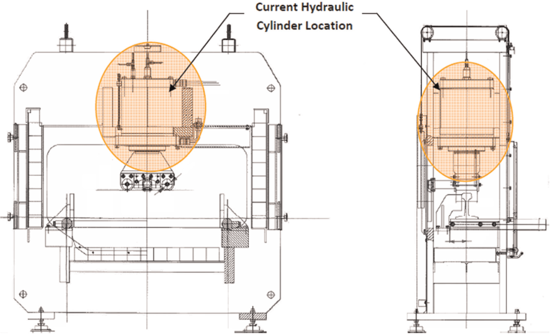
Front and side views of the current rail bend test machine.
Dual hydraulic cylinder
The second design concept follows the same idea that an increased cylinder area will increase the output force; however, it is suggested to keep the existing cylinder and purchase a new cylinder with a small size in comparison to the large size in the first design. The corresponding machine configuration is shown in Figure 6. The hydraulic fluid would be routed from the existing pump to both cylinders. Each cylinder would produce half of the force needed to deflect the beam. If the bore of the new cylinder differs from that of the current cylinder, pressure regulating valves would be needed to equalize the force output by each cylinder. In this case, the frame must be modified to mount both the cylinders, which depends on the existing frame to have sufficient space to hold both cylinders.
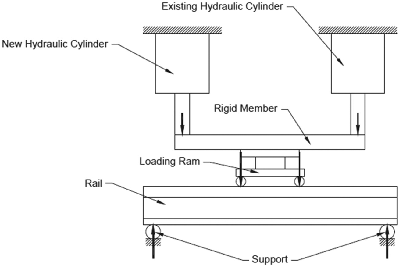
Schematic representation of the dual-cylinder design concept.
Mechanical lever
The output force can be enlarged by an extra mechanism such as a mechanical level. Therefore, the third design option is to incorporate a lever arm; this mechanical arm would act to proportionally increase the force applied by the cylinder. As seen in the conceptual diagram found in Figure 7, the current cylinder would be relocated behind the frame and inverted. The geometries of the lever arm and supports can be optimized based on the maximized loads required at two ends. The cylinder would apply an upward force to a lever arm, which would pivot about a fulcrum fixed to the frame. The opposite end of the lever arm would apply a downward force onto the loading ram. By changing the length of the lever arm and the relative location of the fulcrum, the magnitude of the load applied to the beam could be altered. For this design option, the cost of mechanical components and frame restructure would be significantly reduced in contrast to a new power cylinder, and the load capability can be customized easily. However, the support frame would need remodeling to accommodate the leverage device and the relation of the power cylinder takes a large footprint of the test machine. In addition, the pivoted joints located at the fulcrum experience large amounts of stress.
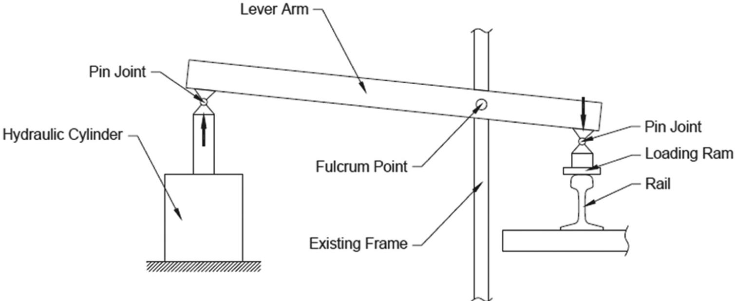
Schematic representation of the mechanical lever concept.
Pump replacement
The fourth conceptual design would involve in replacing the hydraulic pump to increase the pressure delivered to the cylinder. The increase in pressure would correlate to an increased force output by the cylinder. Its advantages are as follows: (1) the mechanical components of the current system would be left unchanged and (2) no modifications to the control system would be necessary. However, the hydraulic components would need to be rated for the new working pressure.
Conceptual design evaluation
The four conceptual designs were then evaluated in order to determine the final design. The decision matrix in Table 1 was constructed with six parameters of varying weights. Each concept was then given a score for each category. The scores in Table 1 are given based on the interviews with responsible test engineers in the client employer. The cylinder and pump replacement concepts scored the highest. The mechanical lever and dual-cylinder designs scored the lowest due to the restrictions for the design.
Decision matrix for conceptual designs.
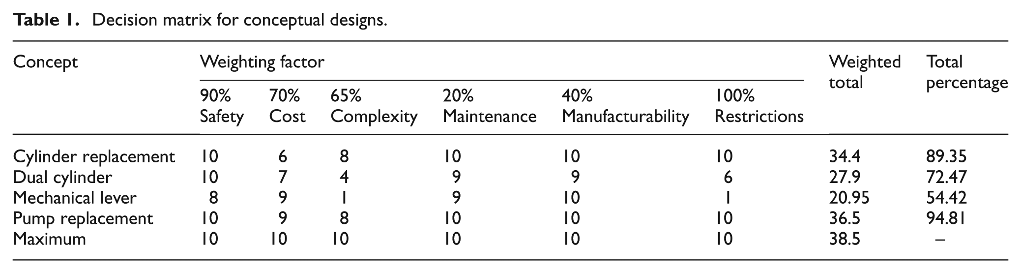
Both the pump and cylinder replacement designs were then examined. It was found that at the current working pressure, the current hydraulic cylinder had a safety factor of 4. This was the minimum desired safety factor for the hydraulic cylinder; therefore, the working pressure could not be increased without replacing the hydraulic cylinder. This would significantly increase the cost for the pump replacement concept, which was the only parameter in which the two designs differed. Therefore, the hydraulic cylinder replacement was chosen as the final design.
Detailed design
Determination of cylinder size
The final selected design is to replace the existing cylinder with a new one with a large bore size. Given the nominal pressure of fluid, the output force on press is proportional to the effective cross-sectional area of the cylinder. The working fluid of the existing system is specified as 3.5 × 10⁷ Pa. To increase the output force to 2700 kN, the bore of the cylinder can be determined by
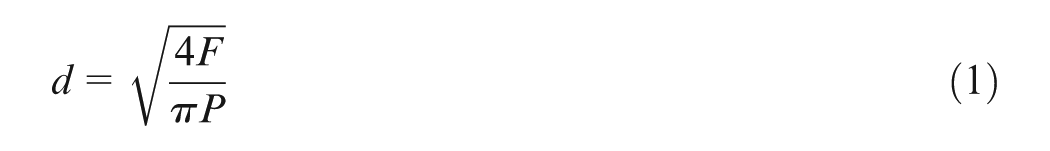
where d is the cylinder bore (m); F is the required force (N), which is 2700 kN in new design; and P is the working pressure (Pa).
As a result, a new cylinder with a bore size of d = 0.3048 m has been chosen; the required peak force can be generated using the current working pressure. Note that the original bore size is d = 0.254 m, which is obviously insufficient to ensure the increased load for new products.
Structure reinforcement
The increase in output force on the press brings the challenge to the existing frame. Therefore, its structure should be remodeled and reinforced to endure the increased load within an acceptable range of deformation. Based on our engineering analysis and numerical simulation, the new structure includes the following new components: (1) the buffer, (2) the block, (3) the vertical column support, and (4) the bottom support.
As highlighted in Figure 8(a), the buffer is made of AISI 4140 normalized steel; its purpose is to withstand the maximum pressure transferred from the load cell and to distribute the force along a greater area such that the A36 block would not fail. The cylindrical shape was chosen to reduce the area, thus reducing cost. Its thickness of 76.2 mm was chosen to ensure that the load cell, when placed on top of the buffer, would be in length of the stroke of the hydraulic cylinder. The diameter of 203.2 mm was chosen so that the force was applied over a greater area, reducing the stress on the A36 block.
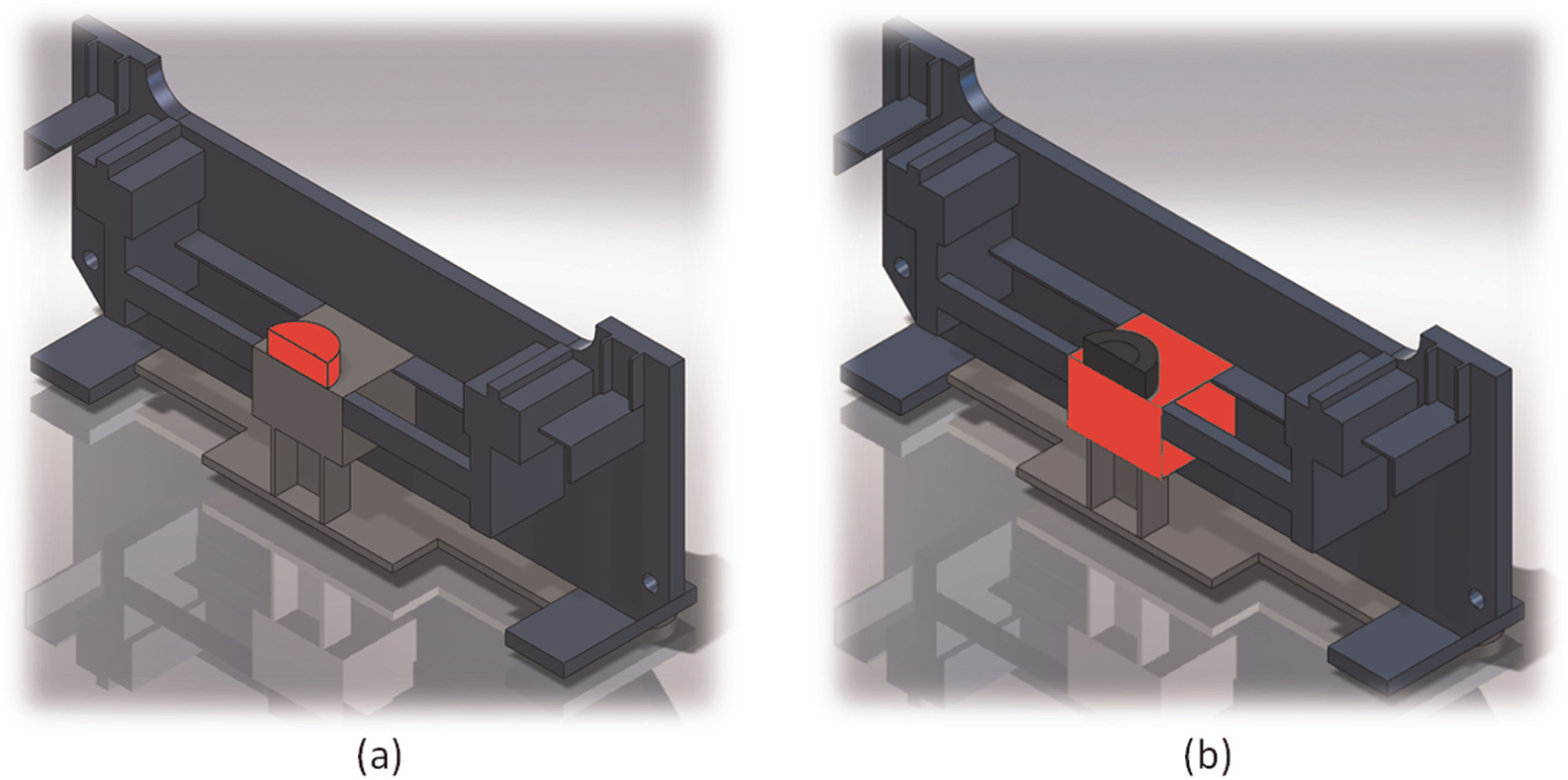
Highlighted (a) buffer and (b) block.
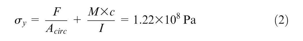
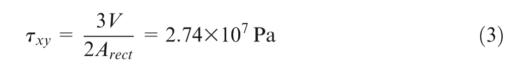
As highlighted in Figure 8(b), the block is made of A36 steel; its purpose is to endure the majority of the distributed force from the buffer. The block has dimensions of 496.3 mm in length, 304.8 mm in width, and 203.2 mm in depth. To place the block onto the frame, the T-beam and L-brackets were cut out in the center. This did not violate our requirements of extensively modifying or removing parts from the frame because these three pieces serve a minor role. Their purpose is to simply hold wooden blocks that are meant to absorb and ensure that the frame is safe from the rupturing rails during the bend test. The block is to be welded on the inner surfaces of the front and back plates of the frame, and from where the block contacts the T-beam and L-brackets. The block experiences multiaxial stresses: a normal compressive stress from the load cell, bending stress due to the moment caused from the frame, and the shear stress at the contact point on the fixed rigid ends. To determine the moment and shear force, the block undergoes the diagram of free body with shear force and moment was created, as shown in Figure 9(a), using an available tool online. 27 The pressure, dimensions, and mechanical properties of the block are given, as shown in Figure 9(b). Note that the pressure in Figure 9(b) was defined based on the requirement of maximized load of 11092.52 kN/m. The results of shear and bending moments are provided in Figure 10(a) and (b), respectively.
Therefore
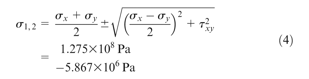
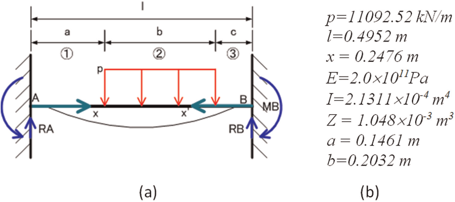
(a) Free body diagram and (b) load and parameters of the support bed.
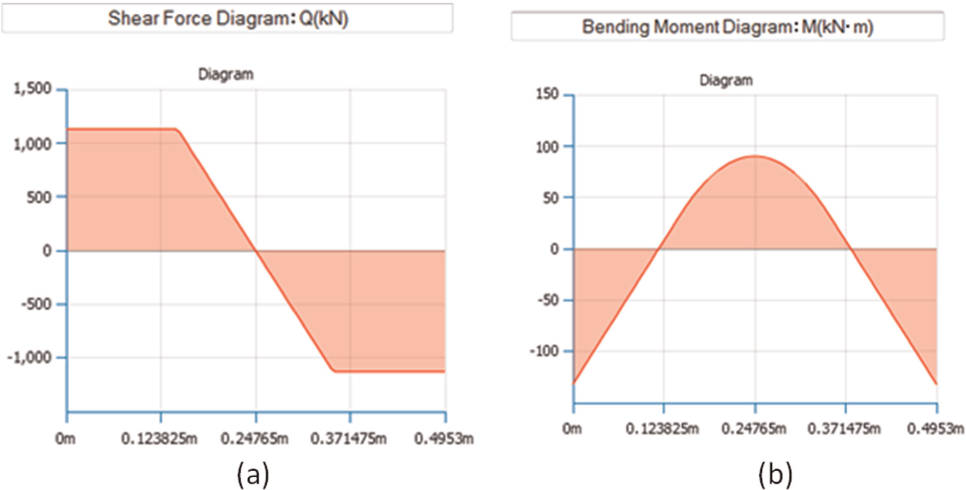
(a) Shearing force and (b) bending moment on the support bed.
And the factor of safety for the block can be determined as
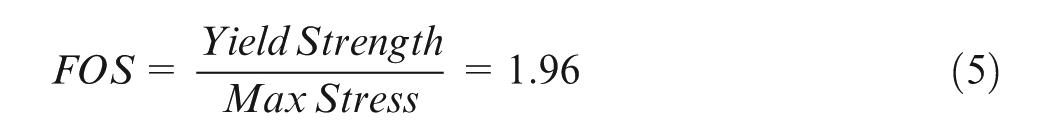
With a minimal requirement of the factor of safety with 1.5, the dimensions for the buffer and the block were proven to be adequate. Note that the preliminary estimation at the conceptual design does not take into consideration stress concentration. However, stress concentration factors can be naturally assessed based on the numerical simulation in section “Numerical simulation.”
The vertical column support and the bottom lip have been highlighted in Figure 11(a) and (b), respectively. Both of them are made of A36 steel. The vertical column support is to reduce the bending moment to relieve the stresses on the contact surfaces of the block. And the bottom lip is to increase the flexural stiffness, remove the stress concentrations, and to support the vertical column support.
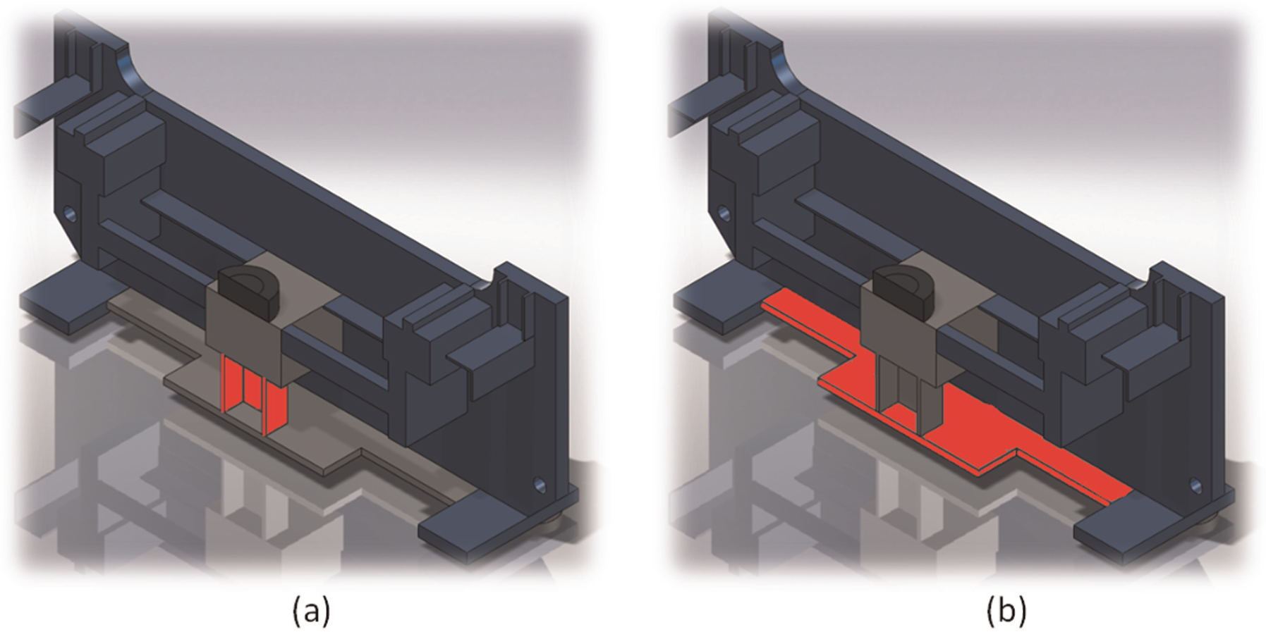
Highlighted (a) vertical column support and (b) bottom lip.
Numerical simulation
The final design was verified via numerical simulation. Multiple tests were simulated for the calibration process and the bend test, and the applied force under consideration is 2700 kN. Minimum safety factors were found for both the calibration and bend tests. Note that the simulation on the calibration process focuses on the strength and rigidity of support base and the simulation on the bend test focuses on the strength of frame. Figure 12 shows the simulation results for the calibration process. The calibration for a 0.3048-m cylinder has a maximum stress of 1.472 × 10⁸ Pa located at the surface of the block. The minimum factor of safety found is 1.7. This value exceeds the safety factor requirement of 1.5.
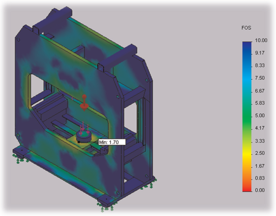
Calibration process was simulated with a force of 2700 kN.
The finite element analysis (FEA) results were compared with experimental data collected from the testing of the implemented design. All testing was performed under the same conditions of the simulated calibration. During testing, the total displacement was measured to be 4.826 mm. The displacement measured was the total distance of extension of the piston, which included the downward displacement of the load cell support as well as the upward displacement of the hydraulic cylinder due to the reaction force. It was found to be consistent with the simulation result.
Implementation
Before all the components are assembled in place, it is necessary to determine the tools available/needed, the maneuverability of the frame, as well as the order in which components are to be installed. The tools necessary are an arc welder and an overhead lift to maneuver the individual parts into place. The client has the capability to maneuver the frame on its side for easy access to install and weld components. The order of installation begins with the bottom lip, then the vertical support column, and finally the block, which is sectioned into three pieces (Figure 13).
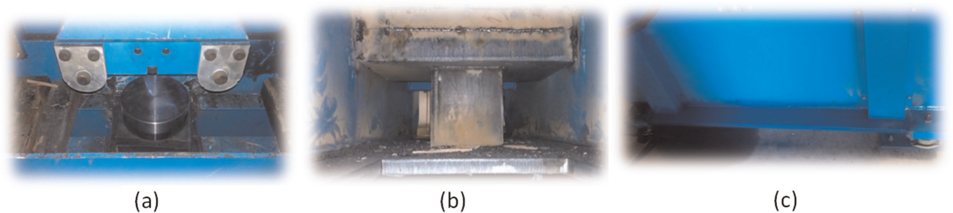
Main parts for the reinforced support bed: (a) inner frame, (b) reinforced support, and (c) bottom lip welds.
Once the bottom lip is installed, the vertical column support is then placed directly center underneath the hydraulic cylinder. To hold the support in place, the outside of the top and bottom flanges are welded to the bottom lip. This ensures no slipping under heavy load. It is not necessary to weld all edges as the weld is not critical to the strength of the column. With the vertical column support installed, all three sections have an eye bolt welded to them. The first section is maneuvered into place with the help of the overhead crane. Each section has a chamfer on both sides that come in contact with the front and back of the frame to ensure deep weld penetration. With the section centered on the vertical column support, it is welded into place. The section void of material where the chamfer was cut is then filled in with weld. When this section cools, the slag is removed and the weld grinded down so the next section lays flat on top of it. The same process is repeated for the remaining two sections of the block.
The build process begins with removing the hoses that connect the pumps to the hydraulic cylinder as well as disconnecting the data acquisition (DAQ) lines to the programmable logic controller (PLC) program. The bottom lip then has two eye bolts welded on opposite ends. Chains and industrial carabineer are then hooked to the eye bolts and overhead crane. The bottom lip is then maneuvered into place and clamped. Every connection between the bottom lip and the existing frame is arc welded per industry standards. The machine is then painted along the new parts for esthetics. Hydraulic lines and DAQ lines are reconnected. Air is purged out of the hydraulic lines and normal operation may resume.
Test calibration
The focus of the presented study was to reconfigure the old-fashioned test machine for a high force output in their bend test machine, which verifies weld strength in rails. This would void the manufacturer’s warranty and place the responsibility of maintaining and calibrating the machine to the client. Hence, the calibration process was deemed a top priority.
To test the calibration process, we would need the loading ram to contact the load cell, which sits above the buffer. However, the load cell was not inserted in the machine, but the force and stresses the frame would undergo must be simulated as if it were present in the machine. To do so, the loading ram would make contact with a section of 136RE rail. The 136RE was not tall enough to contact the loading ram, so four small plates were placed underneath it. This setup will accurately simulate the calibration process with the substitution of the shown materials. After conducting this test twice, the following results were found; from inspecting the above figures, both the calibration simulations output a maximum force of 2154 kN and a displacement of 4.826 mm. Figure 14 shows the setup of calibration process and a sample calibration result.
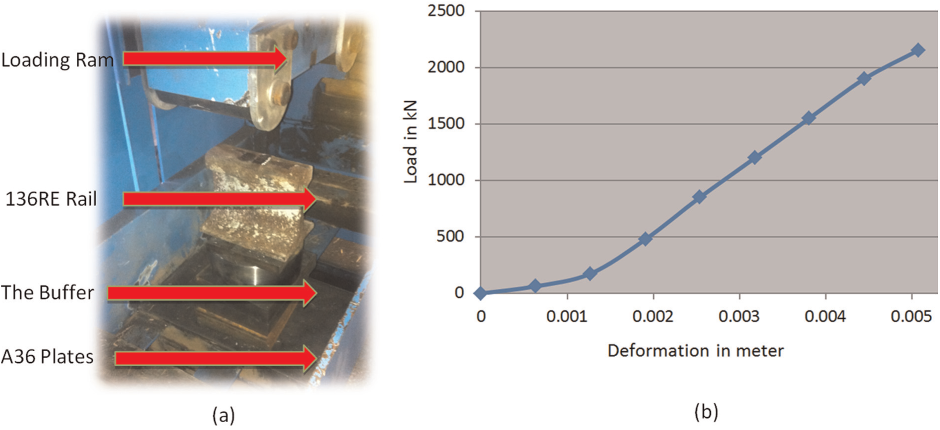
(a) Calibration setup and (b) sample result.
Bend test
To test the rail bend machine under its normal capacity, the bend test was performed for several specimens. In each bend test, a section of rail, with the weld in the center, was placed on the simple supports and the machine is run until the hydraulic cylinder completely extends or the rail ruptures. Figure 15(a) shows a section of 136RE rail-making contact with the loading ram. After the load is applied, the maximum force and displacement outputs were 2000 kN and 14.986 mm, which can be seen in Figure 15(b). The warm-up test had shown that the reconfigured machine is operating appropriately. Since the reconfiguration was completed, the test machine has been running for a year; the machine is capable of generating the maximized force of 2700 kN to break specimens with a yielding failure when the user has a need of damage test.
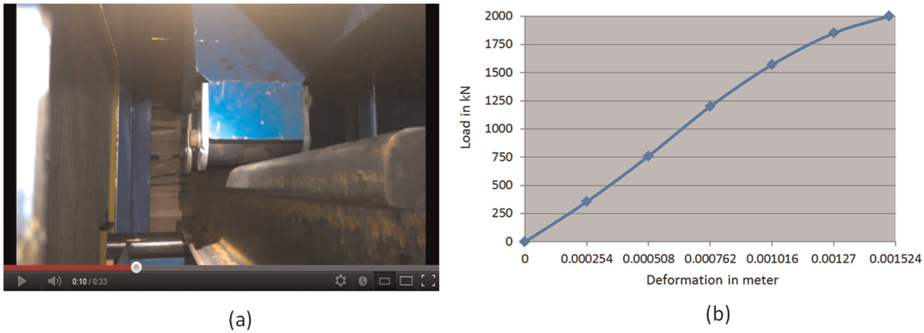
(a) Bend test setup and (b) sample test result.
Efficiency of reconfiguration
The total cost for the reconfiguration of best test machine was US$19,327. The primary objective of the test machine is to be capable of applying quantifiable and sufficient large force to break the specimen; therefore, the precision of test machine is not a critical concern. The cost is the main factor. It included the cost of a new cylinder and the labor cost for fabrication and installations. Surprisingly, it is only 8% of the quoted price of $250,000 from the OEM. The whole process of machine reconfiguration is even shorter than the lead time to acquire a new test machine. In addition, the operational team gained a complete understanding of the machine structure; the remodeled machine can be maintained conveniently by internal staff within the company.
Summary
How to achieve sustainability of manufacturing systems is an emerging research subject; researchers have made great efforts mainly in two aspects: (1) design of new products that can be redesigned, remanufactured, reused, recovered, recycled, and to reduce wastes and (2) design of brand new reconfigurable systems that are capable of changing their configurations to fulfill different functions in present and future applications. However, the endeavor toward these two directions has met some technical bottlenecks such as the challenges of predicting the customers’ future needs, providing an immediate solution to changes, and most importantly, maintaining an affordable cost of system. In this article, a new perspective of system reconfiguration has been proposed and explored; it is based on 4R of existing manufacturing resources. The advantages of implementing such a strategy is that a system configuration can still be designed as a dedicated system with a minimal set of the required functions to meet current customers’ needs; once some changes are involved, system components should be systematically considered to be reused and expanded to accommodate the changes. To illustrate the feasibility and performance of this proposal, the reconfiguration of a bend test machine has been provided as a case study. The machine reconfiguration makes it possible to reuse the majority of existing components, and the whole process only costs less than 8% of a new machine cost; moreover, the reconfiguration time is shorter than the lead time of new machine. However, the readers should note that the feasibility of a reconfiguration of a dedicated machine or a system is not always guaranteed; it is suggested to have a careful assessment before this resolution is taken.
Footnotes
Declaration of conflicting interests
The authors declare that there is no conflict of interest.
Funding
This research received no specific grant from any funding agency in the public, commercial, or not-for-profit sectors.