
Abstract
Multi-part Dedicated Flow-line (MDF) is widely used to produce discrete products for high volumes with low varieties. Since frequent changes occur in customers’ demand and rapid upgrading of machines, the line needs to reconfigure timely to remain competitive. A lot of researchers investigate how to reconfigure the line when facing these changes, and most of them adopts small adjustments such as machine resettlement or buffer size rearrangements to react. However, when great changes occur in product’ machining process or machine’s performance, it’s time to reconfigure the line in a higher level by reselecting machining process of products and/or reselecting machines composition of the line. To fill this research gap, the paper proposes an effective Multi-part Dedicated Flow-line Reconfiguration Model (MDFRM) which can effectively react to great changes occur in products and machines. By optimal selection of Machining Process Path (MPP) for every product and machines composition for the new line, MDFRM can reconfigure MDF with objective of minimizing the products’ cost and capital investment. To solve this problem, an Enhanced Equilibrium Optimizer (EEO) with three layers of code and three steps to handling boundaries and constraints based on Equilibrium Optimizer (EO) is presented. The proposed new model and the designed method are validated by numerical experiments and real case study. This paper will significantly help decision-makers make a scientific decision to optimally reconfigure MDF.
Keywords
Introduction
Nowadays, manufacturing companies face growing changes triggered by fierce competition from around the world, 1 more demanding customers, a rapid changes in product and updating in machining technology. 2 To remain competitive, they have more urgent needs to frequently and rapidly reconfigure the manufacturing systems. Among many types of manufacturing systems, Multi-part Dedicated Flow-line (MDF) is one of the most important ones. It aims to manufacture product with high volumes and low varieties, and is widely applied in many manufacturing contexts which includes machining, assembly, and disassembly. 3 When changes appear in product’s demanding volume, Machining Process Path (MPP) or machining parameters, MDF needs to timely reconfigure. If not, the company’s competitiveness may weaken regards to product’s cost, delivery time, and efficiency of the line, and even lead to the line being unable to produce the product. Furthermore, since MDF is designed for relatively mass production, even the smallest cost or time increase for a single product would contribute a lot to the total variation. So, the investigation of optimal reconfiguring an MDF has a significant meaning.
Numerous researches are conducted to investigate how to reconfigure production line when facing the changes. For reconfiguration of Reconfigurable Manufacture System (RMS), Maniraj et al. 4 propose a novel approach to reconfigure single-product flow-line RMS using ant colony optimization-based approach, Asghar et al. 5 focus on optimal machine capabilities generation by investigating process planning and machine configurations. Ashraf and Hasan 6 propose a framework for configuration selection of a manufacturing flow line. There are some researches performed to analyze MDF for better performance, such as considering buffer sizes and machines types for more accurate performance estimation of series-parallel production line, 7 considering line balance, and throughput analysis to design a multi-part line. 8 Kim et al. 9 investigate maximum production rate and steady-state delay distribution of deterministic serial lines with random setups. For optimal design line’s configuration, Jiang et al. 10 formulate a concurrent optimization model to design assembly line configuration. The model jointly determines the subassembly planning and station assignments considering uncertain product evolution. Moghaddam et al. 11 develop a two phased method to handle the primary system configuration design and the necessary system reconfigurations according to demand rate changes.
However, all of the above research only adopts some small adjustments such as machine resettlement or buffer size rearrangements. They neglect potential great changes in the product (demanding volume, machining parameters, machining process path, etc.) and machines (performance degradation of present-used machine, appearing of new machine with high performance). When these changes occur, the above methods may not work well any longer if present MPP of products is outdated and/or machine’s performance is low. It’s time to reconfigure the line in a higher level by reselecting MPP of products and/or reselecting machines composition of the line. Thus, the objective of the work is to investigate how to reconfigure an MDF when facing great changes related to product and/or machines described above. To solve this production line reconfiguration problem, the paper develops an effective multi-part dedicated flow-line reconfiguration model (MDFRM) and proposes an Enhanced Equilibrium Optimizer (EEO) to solve the model. MDFRM aims to minimize the products’ cost and capital investment by optimal selection of MPP for every product and machines composition for the new line. At the same time, some realistic constraints are considered: demanding volume of the product, workload balance of production line, and maximum machine quantity and type in every machining station.
The proposed MDFRM seeks optimal machines composition under a particular MPP, and it is a new combinatorial optimization problem. Based on the newly proposed Equilibrium Optimizer (EO), 12 the paper proposes an Enhanced Equilibrium Optimizer (EEO). EEO has three layers of code and three steps to handling boundaries and constraints, both numerical experiments and an application case are conducted to validate the proposed MDFRM and EEO.
The rest of the paper is presented as follows: Section “Related works” provides the related research of the investigated problem. Section “Problem statement and modeling” formulates the investigated problem. In Section “Proposed method” the proposed method to solve this new problem is described. Section “Numerical experiments and application case study” conducts both numerical experiments and a real case study to show the effectiveness and applicability of the proposed model and method. Finally, the conclusion is drawn and future work is discussed in Section “Conclusion and future work”
Related works
Over the years, a large body of research has been devoted to the reconfiguration of manufacturing systems to deal with the changes of products and machines mainly for RMS. Battaïa et al. 13 formalize a mixed-integer programming model for flow lines composed of reconfigurable machines which aims to minimize machines cost while satisfying a given throughput and some constraints concerned. Dou et al. 14 investigate reconfigurable flow lines to optimize the total investment for single and multi-part flow lines, respectively. Bahalke et al. 15 study configuration selection of a single product flow-line reconfigurable manufacturing systems using ant colony optimization approach.
It is acknowledged RMS consists of machines that have adjustable structures/modals, 16 which means the machine is much costlier than a dedicated machine since it has much more complicated structures and auxiliary parts. Meanwhile, in some industrials which need to manufacture the product with high volumes, such as car industry, electronic product and household appliance, 17 MDF is widely used to obtain high production rate and low cost. There have some analysis of MDF conducted for higher performance. Tang et al. 8 investigate how to design a multi-part line with the consideration of line balance, equipment selection, and output analysis. Nahas et al. 7 propose a new model that extends the classical buffer space allocation problems by analyzing buffer sizes and types of machines, as well as the number of parallel machines, to estimate series-parallel line’s performance. Li et al. 18 present a hybrid cell evaluated genetic algorithm to optimize the dedicated remanufacturing line by simulation. To evaluate and improve the performance of long stochastic flow lines with finite raw material in discontinuous and continuous time, Mindlina et al. 19 present a flexible (mixed-integer) linear programming approach. Magnanini et al. 20 propose a new model to evaluate performance of asynchronous two-stage production lines manufacturing discrete parts with limited buffer. In summary, all of above research focuses on how to improve the performance of MDF by small rearrangements, such as resettlement of machine or buffer size. These adjustments lead to a satisfied result when small changes appear in product’s demanding volume, MPP and machining parameters. Nevertheless, if present MPP of products is outdated and/or machine’s performance is deteriorated seriously, the above small adjustments may not work well any longer. It’s time to reconfigure the line in a higher level by reselecting MPP of products and/or reselecting machines. To the best knowledge of the authors, there is no comprehensive research to reconfigurate a MDF in terms of selecting product’s MPP and machines (among new and old machines).
Based on the above review, this paper proposes an effective MDFRM which aims to minimize the products’ cost and capital investment by selecting the optimal MPP for products and machine composition. Since the proposed model is a combinatorial optimization problem, and intelligent metaheuristic algorithms have been widely used to solve such problems.21,22 Ouaarab et al. 23 present an enhanced and discrete version of the cuckoo search algorithm for traveling salesman problem, an NP-hard combinatorial optimization problem. Wang et al. 24 present a tabu-genetic algorithm to find the optimal solution for parallel machine scheduling problem with restrained tool resources. Wunnava et al. 25 propose a new optimization algorithm-adaptive equilibrium optimizer for multilevel thresholding problem, based on the original Equilibrium Optimizer (EO). Among many algorithms, newly developed EO 12 demonstrates high effectiveness and efficiency in a lot of problem investigated which motivates us to explore EO to solve the proposed MDFRM.
Problem statement and modeling
Problem description
MDF needs to adjust if changes appear in product, machine, or expectation of the line’s performance. Moderate adjustments, such as relocation of machine or resettlement of buffer size, may function well to deal with small changes. However, great changes may occur in product’s demanding volume, machining process or machining parameters, or present machine deteriorates with new machine of high performance appears. Then we need to reconfigure the line in a higher level by reselecting MPP of products and/or reselecting machines composition of the line instead of small adjustments.
When to reconfigure the production line, the most important is to determine product’s MPP
26
and line’s machine composition,
27
and Figure 1 is a simple demonstration of the investigated MDF reconfiguration problem. In Figure 1, the line is expected to produce two products (
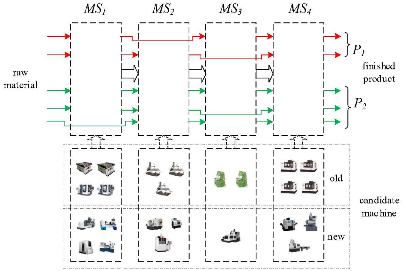
A simple demonstration of the investigated MDF reconfiguration problem.
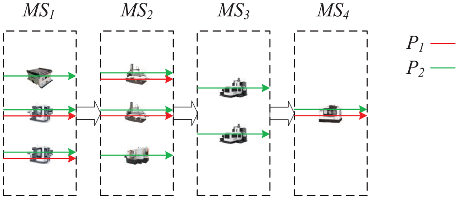
A possible new line as to problem described in Figure 1.
To simplify the problem, assumptions are listed as bellows:
When assigning more than one machine to perform one operation of the product, the product is expected to be processed on the machine whose waiting time is the shortest.
All the machine has perfect machining quality and produce no defect product.
Machining parameters (machining time and cost) are treated as deterministic and constant because of large volume production. 28
The presented model
The notations employed in formulating MDFRM are first defined, followed by the mathematical model.
Notations
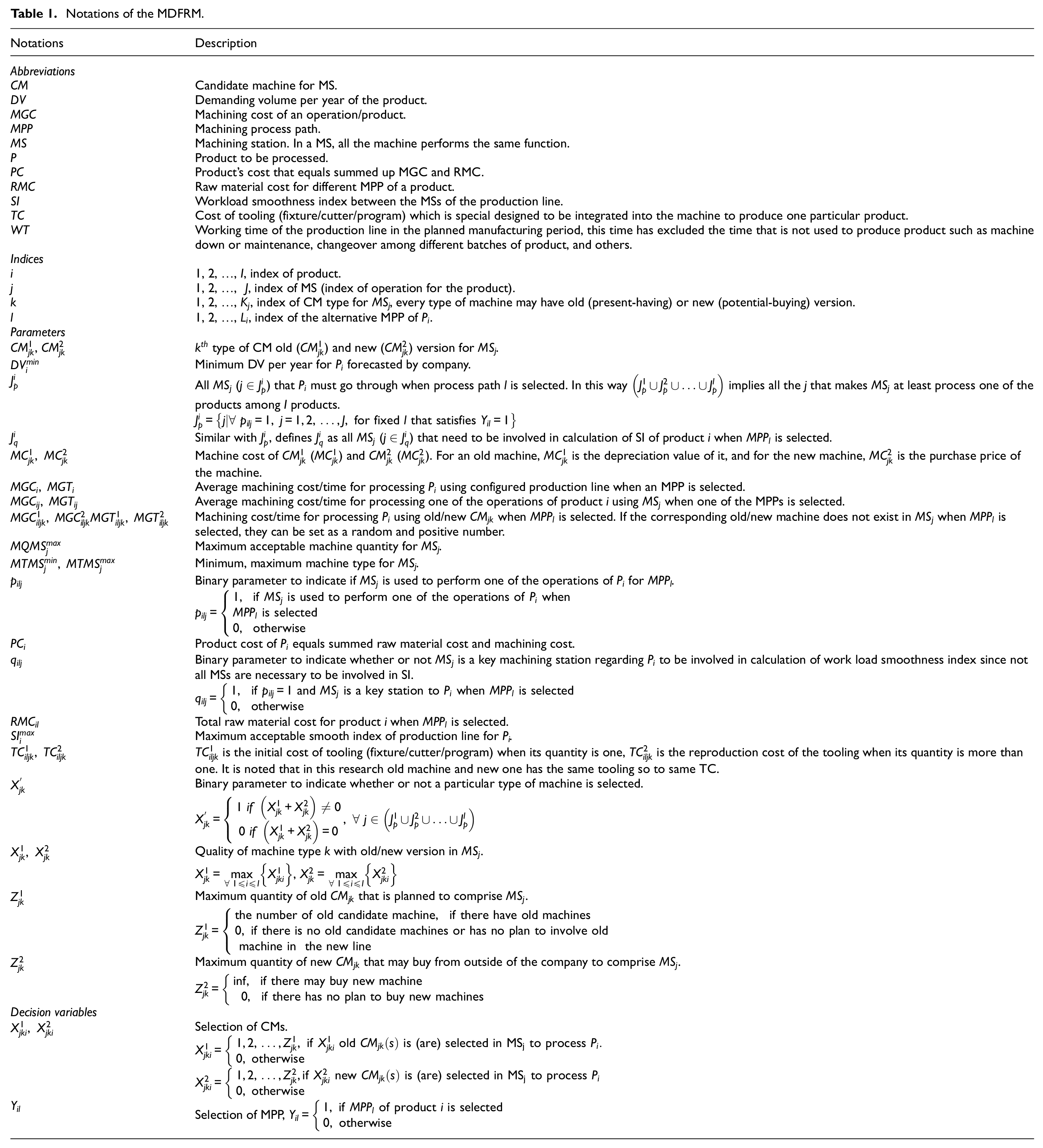
To formulate the problem, the following abbreviation, indices, parameters, and variables are employed (Table 1).
Notations of the MDFRM.
Mathematical model
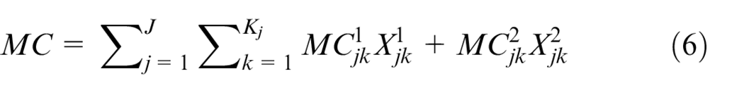
Machining parameters aggregation
Before stating the constraints and objective function, it is necessary to aggregate machining parameters (MGT and MGC) from a single machine to MS level, then to the production line level, since objective and constraints are directly related to these aggregated parameters.
Firstly, we should aggregate parameters of parallel machines to MS level as shown in Figure 3. Since the products are produced in a long production time duration (relative to the cycle time), we can calculate average machining parameters (MGT and MGC) of the product as follows: when
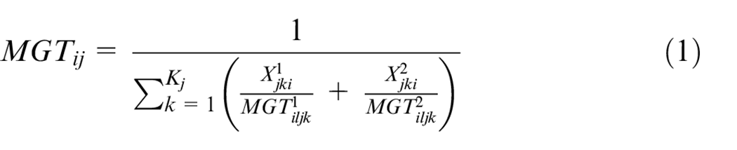
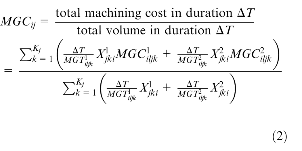
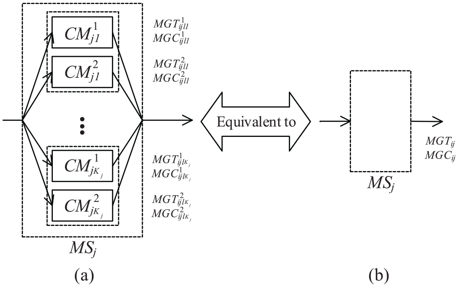
Aggregation of parallel machines: (a) MS with parallel machines and (b) aggregated model of a MS.
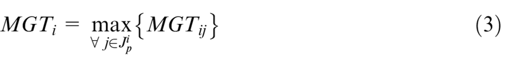
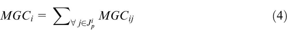
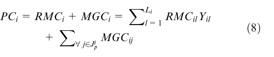
Secondly, machining parameters of the production line level can be calculated as 28 :
Objective
The investigated problem simultaneously minimizes the production line’s total capital investment cost (MC and TC) and product’s cost (RMC and MGC). Because of dissimilar measurement ways and dimensions of objective values, we adopt Simple Additive Weighting (SAW) 29 method to aggregate the objective values into one as equation (5).
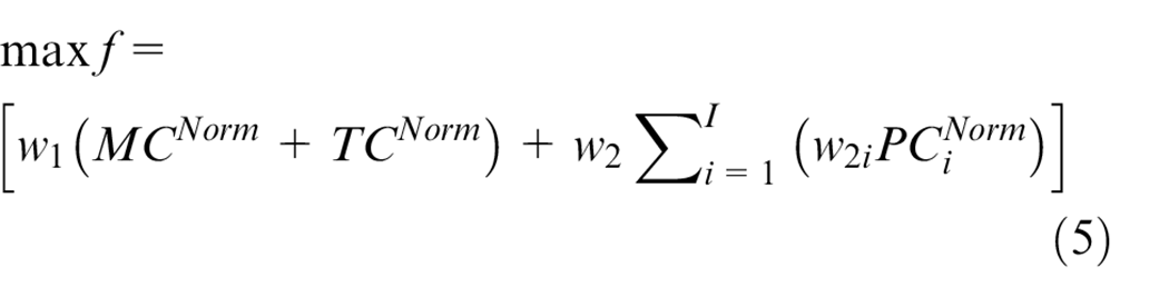
Where

Constraints
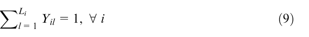
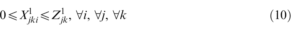
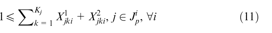
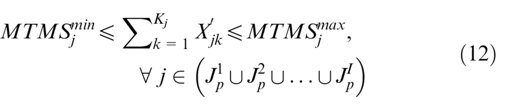
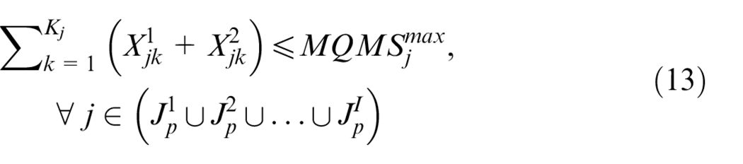
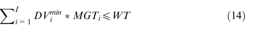
Equation (9) restricts one and only one MPP is selected for every product. Equation (10) ensures every machine’s quantity should not exceed the maximum number that the company present has. Equation (11) ensures every MS that is selected by one or more products should at least select one machine. Equation (12) implies that total machines types in every MS should be in a range defined by decision-maker. From the view of technical risk and supply security, it is important to have several types of machines so that the MS will not rely on one type of machine too much. At the same time, too many machine types in one MS will lead to various types fixtures, and workers with different skills, which result in complicated management. Equation (13) restricts the quantity of the machines in a MS since in real situations machines quantity is not infinite due to the finite size of the plant or limited investment budget. Equation (14) ensures the total machining time of all products with the required minimum
Proposed method
Since the investigated problem is a constrained combination optimization problem that resembles the service composition and optimal selection (SCOS) in cloud manufacturing which is a NP-Hard problem, 31 the problem is also NP-hard that cannot be solved within polynomial-time.32,33 For this type of optimization issue, various intelligent algorithms can be applied to get a satisfactory result because of their acceptable computational complexity.34,35 In this section, based on an optimization algorithm – Equilibrium Optimizer (EO), 12 a new algorithm called Enhanced Equilibrium Optimizer (EEO) is presented. The new algorithm has three layers of code and three steps to handling boundaries and constraints and it can better accommodate the proposed problem.
The presented EEO has the same updating mechanism of particle’s position with the original EO, but has two improvements: three layers of code and three steps to handling boundaries and constraints which will be depicted in this part. Some other adaptive adjustments to solve the proposed problem (including initialization and fitness evaluation) are also presented here.
Three layers of code
When applying a meta-heuristic optimization algorithm for discrete optimization problems, the encoding and decoding scheme plays an important role. 36 In this part, we propose a three layers coding scheme and a coding example for the problem in section “Application case study” is shown in Figure 4 (layer 1: MPP selection) and Figure 5 (layer 2 and 3: machine selection).
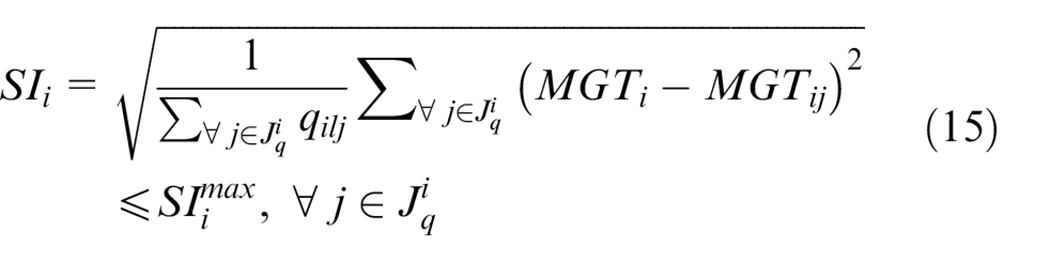
(1) Coding layer 1: MPP selection
MPP selection using index defined in section “Notations” to code and one example is shown in Figure 4. The lower boundary (LB) for all products is one (there has at least one MPP for every product), and the upper boundary (UB) is
(2) Coding layer 2–3: machine selection
Coding scheme for MPP selection.
Machine selection decision variables (
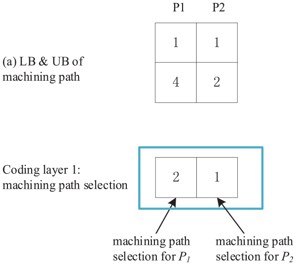
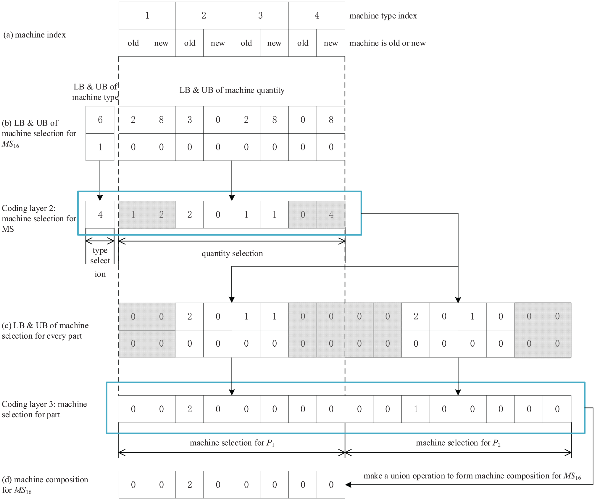
Due to the drawback of the method mentioned above, we proposed a two layers machine selection code scheme for machine selection. In coding layer 2, we select machines for MS (much easier to meet MTMS and MQMS constraints), and in coding layer 3 we select machines among selected ones in MS in coding layer 2. Using this scheme, a machine selection code example of the problem in section “Application case study” is shown in Figure 5.
Proposed coding scheme for machine selection.
In coding layer 2, we select machine by selecting machine’s type and quantity. For machine type selection layer, the code represents machine type selection index which is generated at the very beginning of the algorithm and the generating method is as follows. Listing all possible machine type combinations by selecting
All machine combinations of MS16 for problem in section “Application case study”
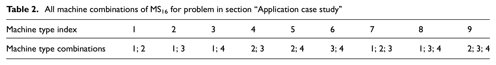
For machine quantity selection layer, the number represents the quantity of the corresponding machines. LB of machine quantity selection for every machine is 0, and UB is the smaller one between MQMS and
coding layer 3 is the machine selection for every product. Its coding number also represents the quantity of the corresponding machines and the boundary is determined by layer 2 which is shown in (c) (the code with gray background means it is blocked due to it is not selected in the machine type selection). We can generate actual machine composition for MS as shown in (d) of Figure 5 by making a union operation of every product’s machine selection. Note that, in the process of making the union, only when a product should be processed on this MS (
Initialization
To generate the initial particle’s concentration more diverse, randomly generation method is adopted.
Three steps to handling boundaries and constraints
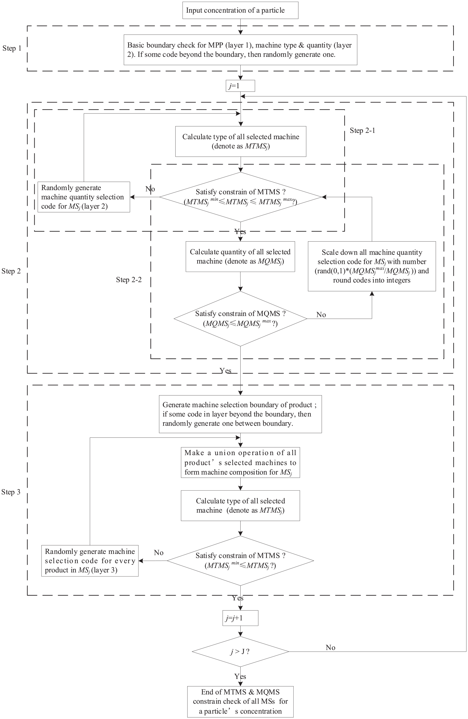
To accommodate the proposed coding scheme, a three steps to handling boundaries and constraints procedure is presented to handle MTMS and MQMS constraints and its’ framework is shown in Figure 6. The following is the constraint check procedure of a single MS.
(1) Step 1: basic boundary check
In this step, basic boundary check is conducted for MPP code in layer 1, machine type and machine quantity code in layer 2, and their corresponding LB and UB are described in section “Three layers of code” If a code beyond the boundary, then a randomly generated code will replace the illegal one. Actually, for the initial solution, all the codes are in the range of LB and UB. However, for the updated solutions, some codes may beyond the boundary because of operations of the algorithm.
Three steps to handling boundaries and constraints.
(2) Step 2: MTMS and MQMS constraints check for MS
This step aims to make sure all MS’s machine composition satisfy MTMS (step 2-1) and MQMS (Step 2-2) constraints in layer 2 so to provide satisfied candidate machines for the machine selection of products.
For MTMS constraint, we have designed machine type selection code that definitely satisfies MTMS constraint. However, if the corresponding machine quantity for all selected types of machine are zero, even this type of machine is selected in the type selection code, it selects no machine actually. So, we need to check if it satisfies MTMS constraint, if not, we randomly regenerate the machine quantity code. The whole process is shown in Step 2-1 of Figure 6.
For MQMS constraint check, if the quantity of selected type of machine
After Step 1 and Step 2, MTMS and MQMS constraint will be satisfied for MS’s machine code which will be served as candidate machine for all parts to select in Step 3.
(3) Step 3: final MTMS constraint check for MS
Final machine composition in MS is the union of every product’s selected machine (layer 3) which is selected among candidate machines in layer 2. Although candidate machines in layer 2 satisfy MTMS and MQMS constraint, the union of every product’s selected machine may not satisfy MTMS constrain. Because in case of some machines in layer 2 is not selected by all products, final machine type in MS may smaller than
Fitness evaluation
For the solution that meets WT (DV constraint) and
Numerical experiments and application case study
In this section, two kinds of experiments are conducted. For numerical experiments, 18 randomly generated problems of different scales (generation method see in Supplemental File A) are used to validate the proposed model and method. For the real case study, a case motivated by actual demand from our industrial partner is conducted to show the application ability of the proposed model and method.
All experiments are conducted with MATLAB and for every problem, 10 independent runs are carried out to try to eliminate the randomness. 37
Numerical experiments
Parameters setting for EEO
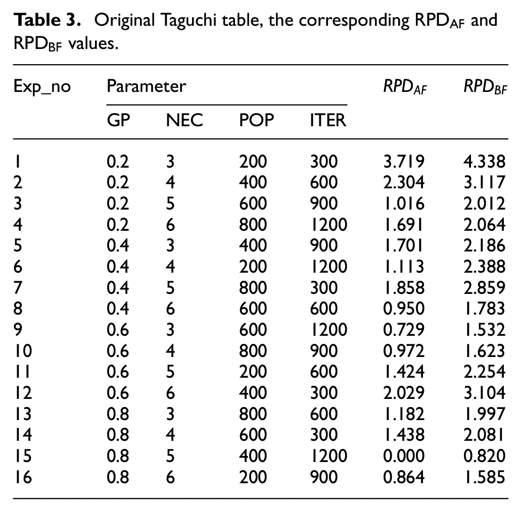
In this section, we investigate the optimum selection of four key parameters for EEO. They include Generation probability (GP), the number of equilibrium candidate (NEC), population size (POP), and maximum iterations (ITER). We adopt the Taguchi method of Design of experiments (DOE) 38 to decide the optimum combination of parameters based on the most complicated problem Pro_18. Four levels of each parameter is considered in this research, that is, GP = [0.2, 0.4, 0.6, 0.8], NEC = [3, 4, 5, 6], POP = [200, 400, 600, 800], ITER = [300, 600, 900, 1200].
The relative percentage decrease (RPD) 39 is used as a performance measure indicator and is computed as follows:
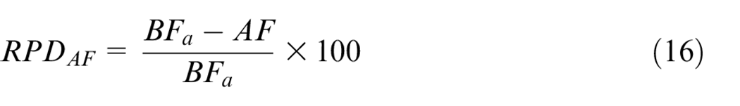
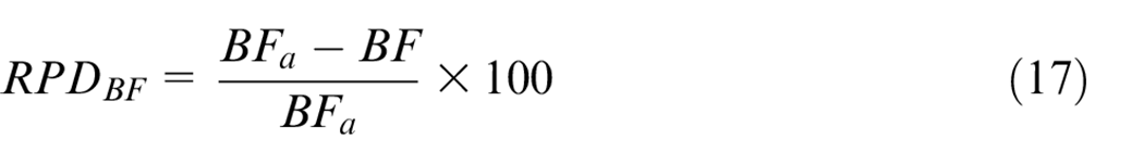
Where
The orthogonal array L16 (i.e. 16 groups of parameter combination are used to conduct the numerical experiments) and the corresponding
Original Taguchi table, the corresponding
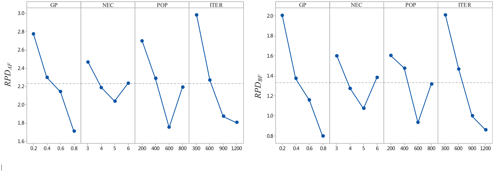
Trend of the level of the parameters in the EO.
Based on the trend of each factor regarding
Comparison of different algorithms
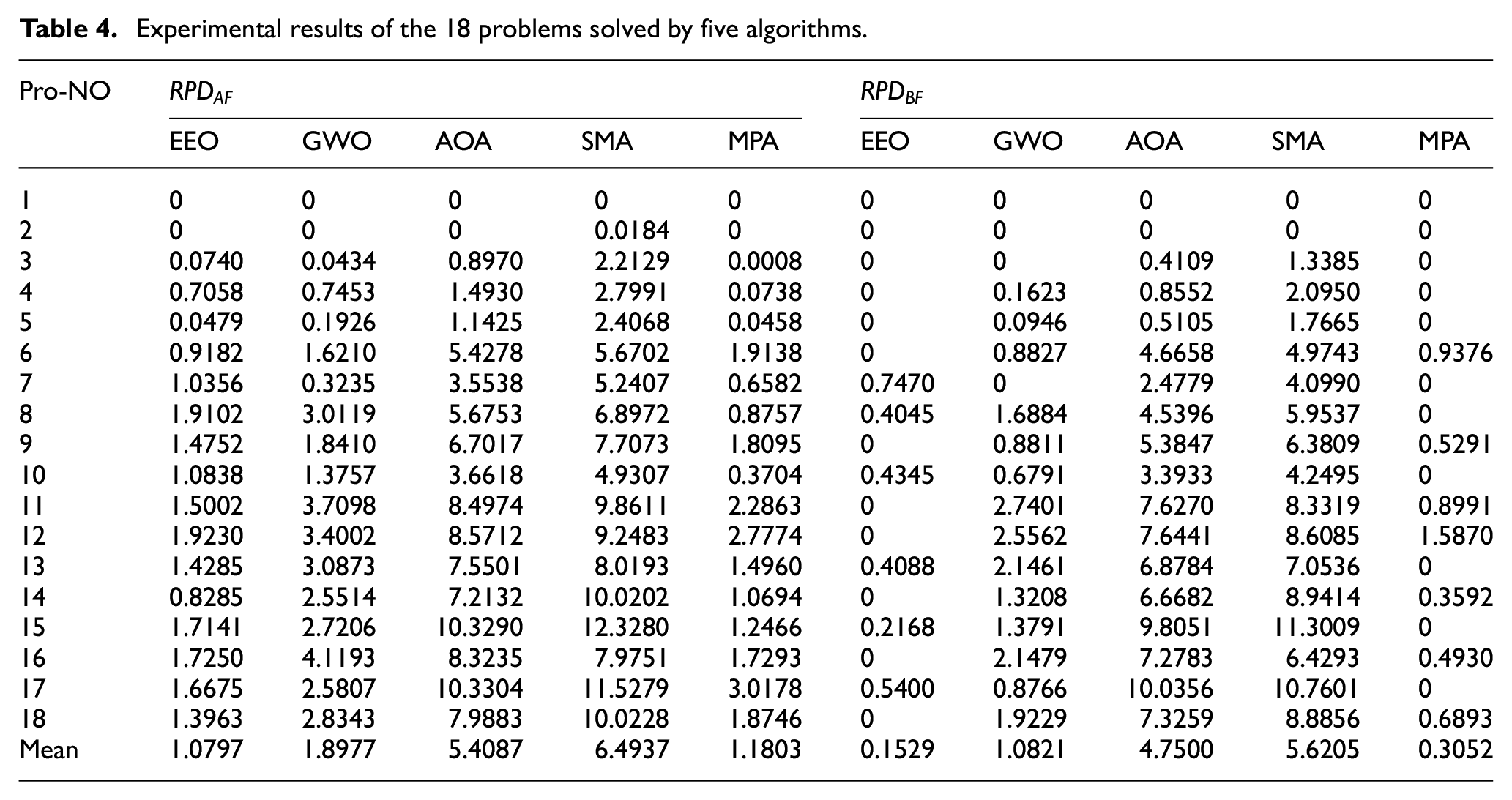
In this section, a comprehensive comparison experiment is conducted on 18 randomly generated problems to find out the best algorithm among the proposed EEO, widely used GWO, and three recently proposed algorithms: AOA, 40 SMA, 41 and MPA. 42 To have a relatively fair comparison, all of the other four algorithms have the same coding and encoding, initialization, and boundary and constraints handling methods, population size and maximum iterations with EEO. The other parameter settings of these algorithms remain the same as those in the literature.
The experimental results of the 18 problems solved separately by five algorithms are shown in Table 4. For
Experimental results of the 18 problems solved by five algorithms.
As is shown in Figure 8, the box plots of
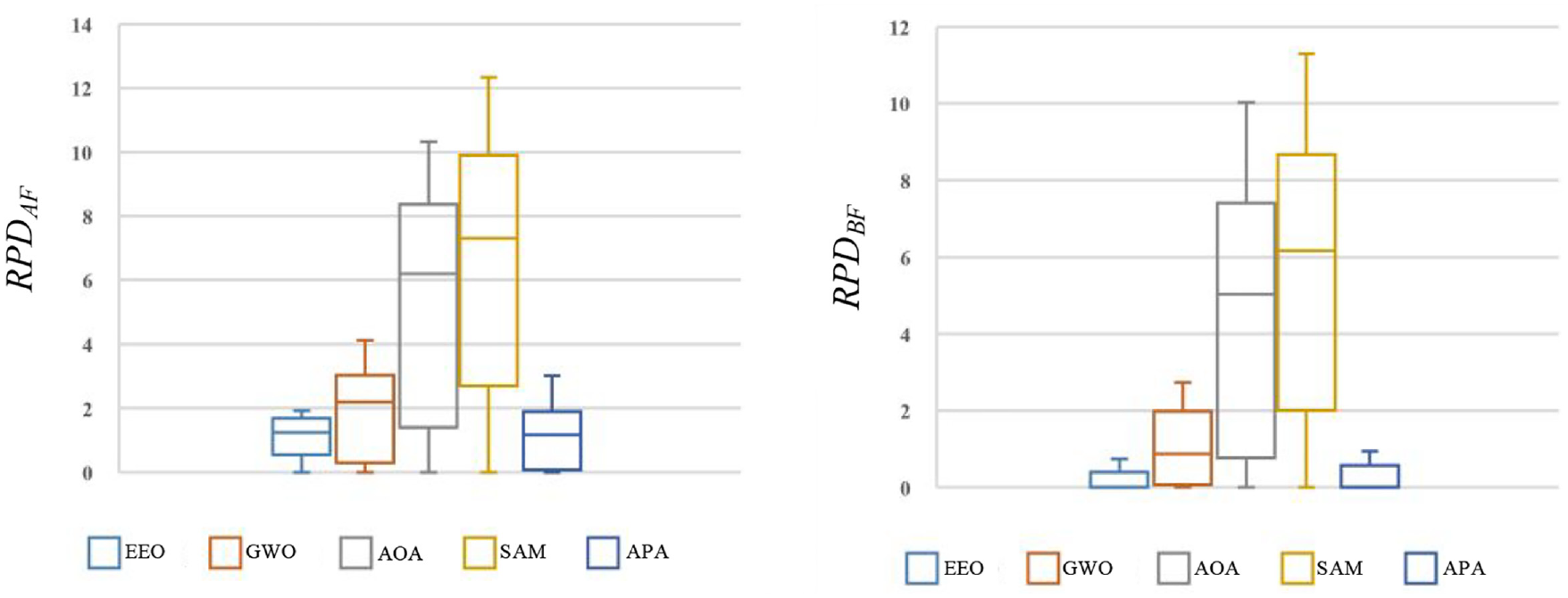
Boxplot of
To further validate EEO’s performance and differences statistically, the Friedman test
43
is utilized and the results are shown in Table 5. From the table we can see that EEO has the highest priority and best mean rank than the rest of four algorithms in terms of both
The Friedman tested results (the level of significant α = 0.05).
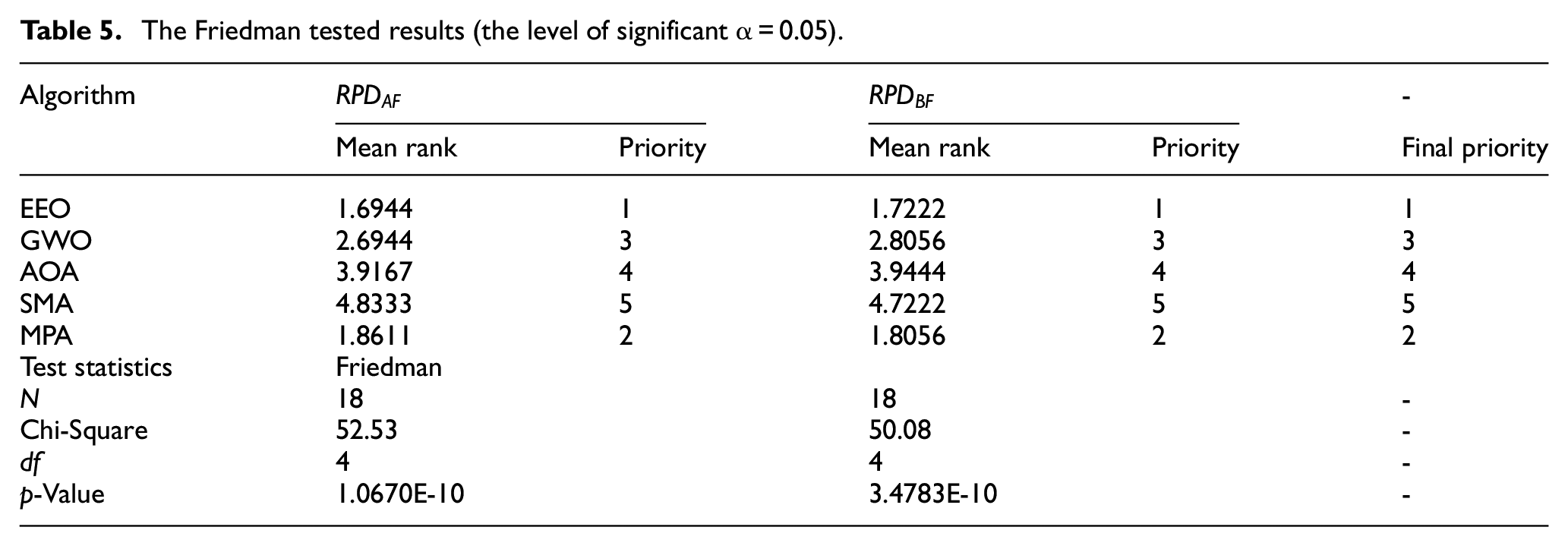
Through the experiments and a series analysis of results above, we can conclude that EEO demonstrates an outstanding performance regarding the investigated MDFRM.
Application case study
An application case study that comes from our industrial partner is shown below to demonstrate the applicability of the proposed MDFRM and EEO. The partner sells more than 1 million residential water heaters yearly in China. As one the most important part of a residential storage water heater, the inner water tank is used to store hot water. The investigated production line can produce two kinds of the inner water tank in separate batch, since they have some common operations (shares some MS). Now, due to the reduced machining performance of some machines, as well as the emerging of well-equipped machines and product’s demanding volume change, there is a need to reconfigure the production line to seek better performance.
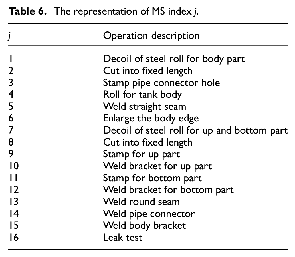
The two kinds of the inner water tank are shown in Figure 9, and their alternative network representation of MPP is shown in Figure 10, in which the meaning of the number is MS index j that can be found in Table 6. In Figure 10, MPP that starts and ends with the same OR-connector, only one of the OR paths will be chosen. As for the links that are not connected by OR-connectors, all of them shall be traversed. We use number “1” to indicate a product should be processed on the corresponding operation, “0” to show not necessary. In this way, Figure 10 can be converted into the second row in Table B1 of Supplemental File B in which
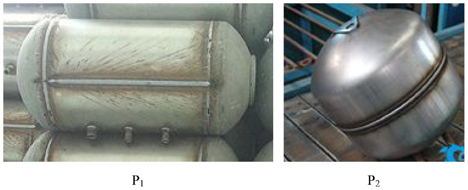
Investigated two inner water tank.
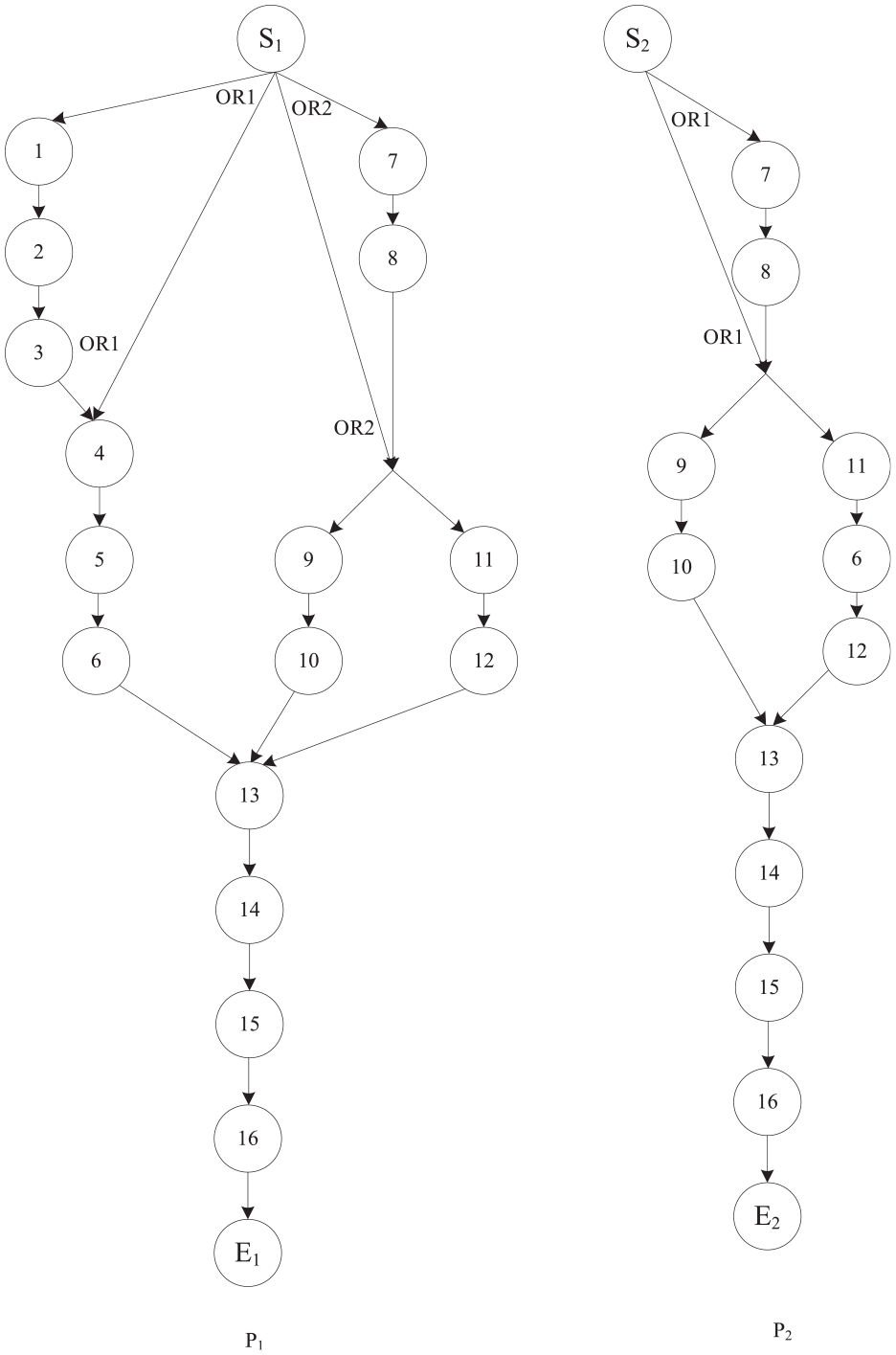
Network representation of alternative MPP of the two products.
The representation of MS index j.
After implementing EEO with 10 runs, the results are: 0.5765, 0.5765, 0.5765, 0.5765, 0.5629, 0.5736, 0.5744, 0.5715, 0.5736, 0.5765. Among 10 results, the best fitness is 0.5765 which appears in the first, second, third, fourth, and tenth run, we choose the first run and the convergence curve of it is given in Figure 11. The corresponding encoded solution is shown in Figure 12. Based on the code and the network representation of the MPP in Figure 10 we can form the final production line with machine composition and every product’s machine selection which is shown in Figure 13.
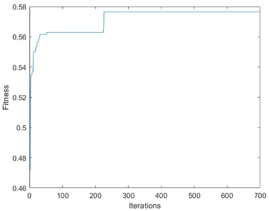
Convergence curve of the best fitness.
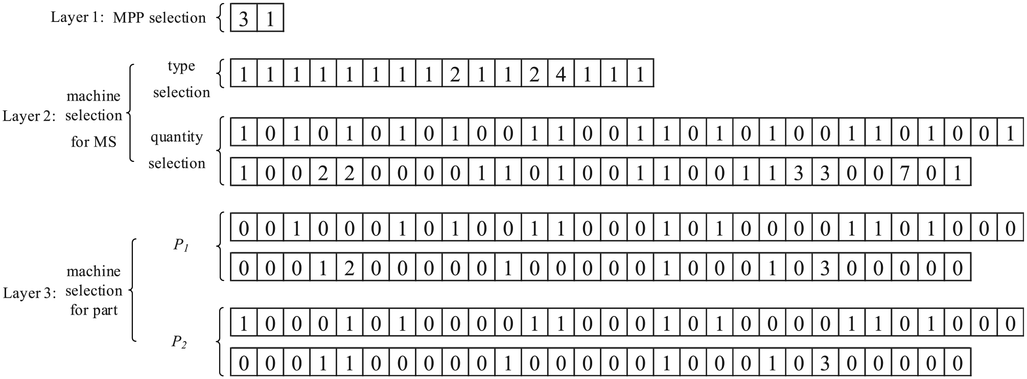
Code of the best solution.
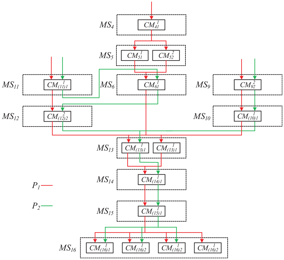
Obtained the best production line configuration.
Conclusion and future work
Multi-part Dedicated Flow-line (MDF) is widely used to produce discrete products for high volumes with low varieties and its reconfiguration problem is of great importance. Present small adjustments such as machine resettlement or buffer size rearrangement cannot work well if MPP of products is outdated and/or present machine’s performance is low. It’s time to reconfigure the line in a higher level by reselecting MPP of products and/or reselecting machines. In this paper, we develop an effective Multi-part Dedicated Flow-line Reconfiguration Model (MDFRM) to help production line owner make a scientific reconfiguration decision when great variations occur in product’s MPP and machines. The model considering multi-model products each with several optional MPPs, old (present-having) as well as new (potential-buying) candidate machines, pursues minimum weighted objective value including production line’s capital investment (machine and tooling cost) and product’s cost (raw material and machining cost). At the same time, every product’s demanding volume, production line’s workload balance, and some other realistic constraints are considered. To solve the proposed MDFRM, an Enhanced Equilibrium Optimizer with three layers of code and three steps to handling boundaries and constraints is proposed. Numerical experiments are conducted based on randomly generated problems, which effectively validate the proposed new model and designed solution. Finally, an industrial case study is conducted to further show the applicability of the model and method for reconfiguration of an inner water tank manufacturing line.
For future work, buffer size between MS can be involved since it influences the throughput capacity when considering variation of actual machining time and machine break down. 44 Furthermore, pursuing optimization of two or more objectives simultaneously to find a set of nondominated solutions (Pareto set)45,46 is also a research direction for the involved problem.
Supplemental Material
sj-docx-1-pib-10.1177_09544054221100873 – Supplemental material for An effective multi-part dedicatedflow-line reconfiguration model considering the optimal selection of machining process path and machines
Supplemental material, sj-docx-1-pib-10.1177_09544054221100873 for An effective multi-part dedicatedflow-line reconfiguration model considering the optimal selection of machining process path and machines by Hao Yu, Bo Yang, Shilong Wang, Yankai Wang, Sibao Wang, Zehua Wang and Zhongning Wang in Proceedings of the Institution of Mechanical Engineers, Part B: Journal of Engineering Manufacture
Footnotes
Author contributions
Hao Yu: Methodology, Formal analysis, Writing original draft, Validation. Bo Yang: Methodology, Writing – review and editing, Funding acquisition. Shilong Wang: Conceptualization, Supervision, Funding acquisition, Project administration. Yankai Wang: Investigation, Formal analysis, Writing – review and editing. Sibao Wang: Supervision, Writing – review and editing. Zehua Wang: Review and editing. Zhongning Wang: Review and editing.
Declaration of conflicting interests
The author(s) declared no potential conflicts of interest with respect to the research, authorship, and/or publication of this article.
Funding
The author(s) disclosed receipt of the following financial support for the research, authorship, and/or publication of this article: This work was supported by the 2030 Innovation Megaprojects of China (Program on New Generation Artificial Intelligence) [Grant No.2018 AAA0101804], the Key Project of Technological Innovation and Application Development Plan of Chongqing [Grant No. cstc2019jscx-mbdxX0056], the Natural Science Foundation of Chongqing (Grant No.cstc2021jcyj-msxmX0732), the Self-Planned Task of State Key Laboratory of Mechanical Transmission (Grant No.SKLMT-ZZKT-2021M03), the Innovation Group Science Fund of Chongqing Natural Science Foundation (Grant No.cstc2019jcyj-cxttX0003), the Independent Research Project of the State Key Laboratory Of Mechanical Transmissions (Grant No.SKLMT-ZZKT-2021R04), and Chongqing Innovation Support Foundation for Returned Overseas Chinese Scholars (Grant No.cx2021035)
Supplemental material
Supplemental material for this article is available online.
References
Supplementary Material
Please find the following supplemental material available below.
For Open Access articles published under a Creative Commons License, all supplemental material carries the same license as the article it is associated with.
For non-Open Access articles published, all supplemental material carries a non-exclusive license, and permission requests for re-use of supplemental material or any part of supplemental material shall be sent directly to the copyright owner as specified in the copyright notice associated with the article.