
Abstract
This article details experimental work performed to evaluate the effects of varying feed rate (0.08 and 0.15 mm/rev) and tool coatings (diamond-like carbon and chemical vapour–deposited diamond) on tool wear modes and hole quality when drilling 30-mm-thick Ti-6Al-4V/carbon fibre–reinforced plastic/Al-7050 stacks in a single-shot operation. At a feed rate of 0.08 mm/rev, the diametrical accuracy of holes produced by both the chemical vapour–deposited diamond and diamond-like carbon–coated drills (6.38 mm diameter) was comparable within a tolerance of ±0.04 mm even after 70 holes. However, in terms of cylindricity, holes machined with chemical vapour–deposited diamond were significantly better than those produced using the diamond-like carbon–coated drills by a factor of ∼2 (65.7 vs 140.6 µm). A similar trend was also observed for hole out of roundness. Burr height at hole entry locations (Ti layer) ranged from ∼0.03 to 0.08 mm for all trials undertaken at the lower feed rate level; however, the diamond-like carbon–coated drills generated exit burrs which were ∼4 times larger than their chemical vapour–deposited diamond-coated counterparts. Subsequent wear analysis showed that diamond-like carbon–coated drills operating at 0.08 mm/rev typically exhibited progressive abrasion, workpiece adhesion and chipping leading to fracture of the tool corner, while fracture due to fatigue was prevalent in tests carried out at the high feed rate level. In contrast, poor adhesion of the chemical vapour–deposited diamond coating to the carbide substrate led to premature flaking, severe chipping and fracture of the drill cutting and chisel edge.
Introduction
The use of multi-element metallic-composite stacks is increasing in the aviation industry for supporting or reinforcing component areas subject to extreme loading such as linkage sections between wing spars/ribs and the aircraft fuselage. While monolithic construction or adhesive joining may be preferable, mechanical fastening is currently the primary assembly route in order to fulfil strength requirements and provide flexibility for part maintenance. However, the drilling of multilayer stacks, comprising, for example, titanium/carbon fibre–reinforced plastic (CFRP)/aluminium, poses significant challenges, not least due to the varying mechanical/physical properties and machinability of the individual workpieces. 1,2 Single-shot operation using conventional hard metal or ceramic-coated tungsten carbide (WC) drills is generally characterised by poor tool life and low productivity. 3 The use of advanced diamond-based coatings such as physical vapour–deposited (PVD) diamond-like carbon (DLC) 4 and chemical vapour–deposited (CVD) 5 diamond products has been proposed as a potential solution, due to their superior mechanical and physical properties.
Current research challenges associated with single-shot drilling of metallic-composite stack materials include identifying preferred process conditions (cutting parameters, tool geometry/material, machining strategy etc.) to achieve the required hole quality and integrity (without recourse to a separate reaming operation) with acceptable tool life. Brinksmeier and Janssen 6 were one of the earliest to publish research involving drilling of three-layer stacks (AlCuMg2/CFRP/Ti-6Al-4V), using 16-mm-diameter uncoated and coated (TiB2 and diamond) WC drills at cutting speeds of 10 and 20 m/min under a constant feed rate of 0.15 mm/rev. They reported that the coatings had minimal effect with regard to tool life, and severe damage of the CFRP hole surface was observed during evacuation of the titanium chips from the bottom of the stack. More recently, Shyha et al. 7 conducted experimental trials to evaluate the influence of varying operating parameters (cutting speed, feed rate and environment) and coatings (uncoated, CVD diamond and a nano-grained AlTiN-coated WC) when drilling 6.35-mm-diameter holes in Ti-6Al-4V/CFRP/Al-7050 stacks. They concluded that the use of high-pressure cutting fluid (70 bar) was critical in maintaining acceptable hole quality (diametrical accuracy, out of roundness and cylindricity) and workpiece integrity and that tool coatings had only a marginal effect. A hole diameter tolerance of ±0.02 mm was achieved even after drilling up to ∼310 holes with out of roundness not exceeding ∼20 µm when operating under a two-stage cutting speed of 20/40/40 m/min (for Ti/CFRP/Al) and feed rate of 0.05 mm/rev. Related work on the performance of the CVD diamond and hard metal AlTiN coatings (nano-crystalline grains embedded in a SiC amorphous matrix) showed that there was no benefit from these coatings in terms of tool life over uncoated WC drills. 8
Zitoune et al. 9 employed K20 carbide drills of various diameters (4–8 mm) with standard point angle of 118° to assess the influence of cutting speed (13–69 m/min) and feed rate (0.05–0.15 mm/rev) on thrust forces, surface finish and hole accuracy, when drilling two-layer CFRP/aluminium stacks. In general, it was found that increasing feed rate and drill diameter decreased chip breakability due to the larger chip cross section, which had a detrimental effect on surface roughness in the Al section. The results, however, suggested a preferred cutting speed and feed rate combination of 38 m/min and 0.10 mm/rev, respectively, which kept the surface roughness in the aluminium layer to ≤1 µm Ra. Corresponding roughness measurements in the CFRP section, however, ranged between 4 and 6 µm Ra (depending on drill diameter), although hole circularity was within ∼6 µm. Carvajal et al. 10 carried out comprehensive statistical analysis on industry data/records in order to determine the influence of drill diameter, cutting speed and feed rate on hole diameter accuracy, when drilling various metallic-composite stack materials. They found that high feed rate levels generally produced lower hole diameter variations in both the metal and composite layers, while cutting speed showed limited influence. In experiments involving drilling of 10-mm-thick graphite/bismaleimide (Gr/Bi) and titanium stacks, Ramulu et al. 11 recommended the use of WC drills (6.35 mm diameter) at a constant feed rate and cutting speed of 0.08 mm/rev and 13.2 m/min, respectively, for best results. The burrs generated were no higher than 0.05 mm at the hole entrance but were ∼10 times larger at the exit location (0.5 mm), while corresponding flank wear was approximately 100 µm after 40 holes. In benchmarking tests, using veined polycrystalline diamond (PCD) drills against conventional WC tools when drilling CFRP/Al and CFRP/Ti stacks at cutting speeds of 180/14 and 358/16 m/min, respectively, the veined PCD drills exhibited up to 5 times longer tool life than the WC products, with hole diameter tolerances of ±0.038 mm and maximum exit burr lengths of 0.20 mm. 12
This article details experimental work to evaluate the effect of diamond-based coatings and feed rate on hole quality as well as tool failure modes when drilling three-layer Ti/CFRP/Al stacks.
Experimental work
Tooling, workpiece material, equipment and test methodology
The drills were twin-fluted, 6.38-mm-diameter, solid WC with either a DLC or CVD diamond coating as shown in Figure 1. Tool geometry of the latter involved a 120°× 180° two-stage point design with a corresponding helix angle of 30°, while the former had a conventional drill edge with point and helix angles of 140° and 30°, respectively. The mechanical and physical properties of the diamond coatings are detailed in Table 1. The workpiece stacks comprised unidirectional CFRP laminates (Young’s modulus, E = 220 GPa), sandwiched between annealed Ti-6Al-4V alloy (E = 114 GPa) and age strengthened Al-7050-T7651 aluminium alloy (E = 72 GPa), in the form of plates measuring 120 × 120 × 30 mm3 and strips with a width of 17 mm (see Figure 2(a)). The CFRP laminates consisted of 30 unidirectional prepregs (individual ply thickness of 0.30 mm) which were laid up according to an orientation of [45°/0°/135°/90°/45°/0°]3s and encompassed a 56% volume fraction of high tensile strength carbon fibres (6–8 µm diameter) within an epoxy matrix. The plates were employed for mainstream tool life/wear testing and were bonded together using a cured adhesive film having an ultimate tensile strength and shear modulus of 48 MPa and 439.1 GPa, respectively. In contrast, the strip specimens were held together using M6 socket screws and were used for cutting force evaluation and subsequent hole quality analysis. All tests were performed on a Matsuura FX-5 machining centre equipped with a retrofit through-tool coolant spindle adapter supplying an emulsion (7%–8% volume of soluble mineral oil in water) at 70 bar pressure and 15 L/min flow rate (see Figure 2(b)).
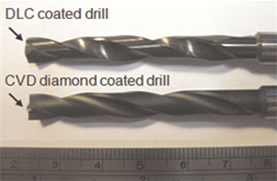
Diamond-coated drills.
Properties of the diamond-based coatings.
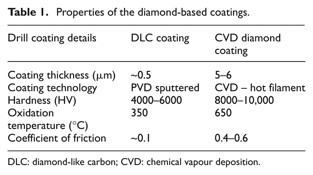
DLC: diamond-like carbon; CVD: chemical vapour deposition.
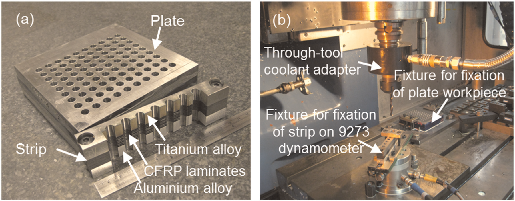
(a) Ti/CFRP/Al stack and (b) experimental set-up.
Four trials were performed to assess the effect of tool coating and feed rate (see Table 2 for test details). Cutting speed was held constant at 30 m/min for the Ti layer and ramped up to 120 m/min for both the CFRP and Al sections in all tests. A pecking cycle where the drill was retracted by 2 mm after machining every 5 mm was also implemented in order to aid chip evacuation. Thrust force and torque were recorded using a Kistler 9273 dynamometer linked to 5011A charge amplifiers with data acquisition and analysis performed on a PC installed with DynoWare software. Drill flank wear was measured using a toolmaker’s microscope mounted on a micrometre stage equipped with a digital camera, while tool wear images were taken using a JEOL 6060 scanning electron microscope (SEM). Hole geometry parameters (diameter, cylindricity and out of roundness) were evaluated using a Taylor Hobson Talyrond 300 by sampling three pitch points (entry, mid-point and exit) in each material section. Three measurements were conducted for each sample and the results averaged. Burr height was measured at four points around the hole via a level-type dial gauge with a resolution of 0.002 mm. All the response measures were taken after hole 1, 10, 20 and 30 followed by intervals of 20 holes thereafter. Each of the drills was tested to fracture/catastrophic failure or a maximum of 90 holes in order to evaluate the type and progression of tool wear.
Test details.
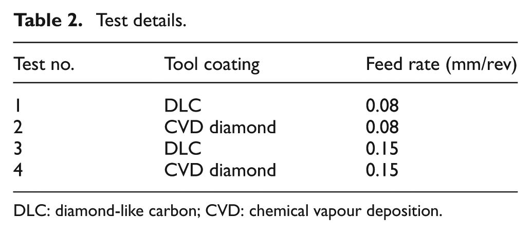
DLC: diamond-like carbon; CVD: chemical vapour deposition.
Results and discussion
Thrust force and torque
Figure 3(a) and (b) details the evolution of thrust force and torque, respectively, in each material section for all experiments. When employing the DLC-coated drill at a feed rate of 0.08 mm/rev (Test 1), thrust forces in the Ti, CFRP and Al layers increased from 526, 222 and 265 N in the first hole to 818, 339 and 346 N, respectively, after only 10 holes. The rapid rise (∼56%) of thrust force in the Ti plate was attributed to the premature chipping and severe adhesion of workpiece material on the drill cutting edge. Similarly, torque increased by twofold to threefold from initial values of 163, 59 and 98 N cm in the Ti, CFRP and Al sections, respectively, after 10 holes. Subsequent rise in both thrust force and torque, however, was gradual until 70 holes, after which the test was halted due to fracture of the drill corner.
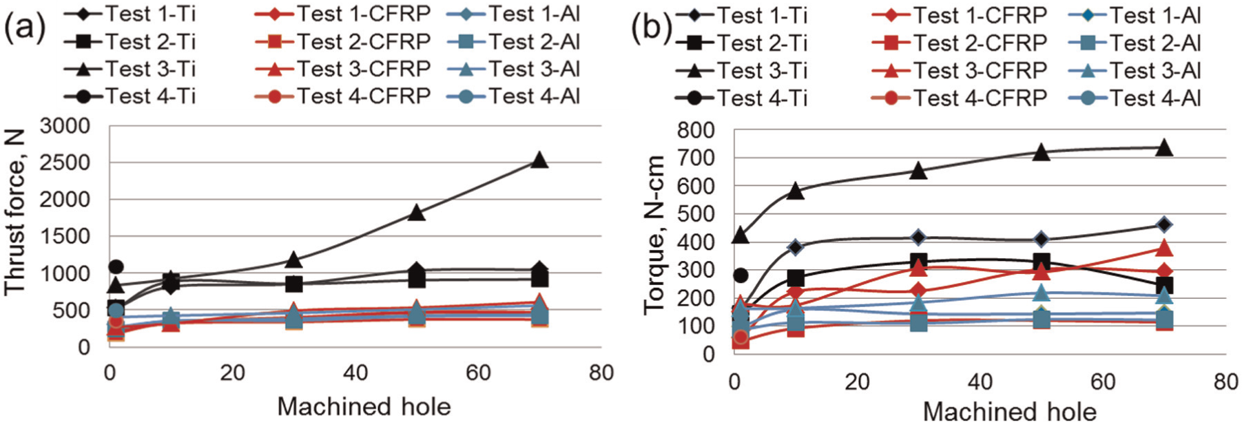
(a) Thrust force and (b) torque results for each material layer in all tests.
Considerably higher initial thrust forces (hole 1) were recorded in all three layers of the stack (Ti – 837 N; CFRP – 276 N; Al – 406 N) as the feed rate of the DLC-coated drill was increased to 0.15 mm/rev (Test 3). While forces in the Al workpiece remained fairly stable (462 N) even after 30 holes, a steady increase of up to 41% (1184 N) and 78% (492 N) in the Ti and CFRP sections, respectively, was observed over the same interval following which complete delamination of the DLC coating occurred on the flank face. This subsequently led to a steep escalation of thrust force in the Ti segment which more than doubled to ∼2500 N after 70 holes. Corresponding torque levels also increased from 427, 179 and 161 N cm to 654, 306 and 184 N cm in the Ti, CFRP and Al sections, respectively, after 30 holes. As with Test 1, the experiment was discontinued after hole 70 due to severe fracture of the cutting lip corner radius.
Despite having a higher coefficient of friction, marginally lower thrust forces (Ti – 524 N; CFRP – 187 N; Al – 243 N) and torque (Ti – 145 N cm; CFRP – 48 N cm; Al – 87 N cm) were obtained (in all layers) when drilling with a CVD diamond-coated drill in the new condition at a feed rate of 0.08 mm/rev (Test 2) compared to the DLC-coated product. This was most likely due to the geometry of the former, which involved a sharper primary point angle (120°) that lowered thrust forces and a secondary angle of 180° that shortened the cutting lips and hence reduced torque. The progression of both thrust force and torque following the first hole was similar to the trend shown in Test 1, with both increasing by ∼70% and 100%, respectively, in the Ti and CFRP sections after 10 holes. Subsequent values stabilised up to 70 holes. When utilising a feed rate of 0.15 mm/rev (Test 4), the CVD diamond drill produced only three holes before catastrophic tool failure, thereby forcing premature termination of the experiment.
Tool wear
The average flank wear of the DLC-coated drill after 70 holes in Test 1 was approximately 110 µm. Figure 4 details corresponding micrographs of the drill at regular intervals over the test duration, which indicated that wear at the cutting edge was triggered by abrasion with signs of micro-chipping after about 10 holes. The formation of a built-up edge (BUE) consisting principally of adhered aluminium alloy initiated after ∼20 holes, particularly near the corner edge. Although not shown here, this was confirmed by energy-dispersive X-ray (EDX) spectroscopy analysis. The adhered layer/BUE continued to grow as machining progressed, which finally led to loss of the DLC coating as the BUE broke off from the drill surface. The repeated process of adhered material build-up and removal eventually resulted in weakening and ultimately fracture of the drill corner. Subsequent SEM analysis of the worn drill showed chipping marks on the DLC coating and exposed carbide substrate at the corner together with evidence of epoxy matrix residue attached to the cutting edge.
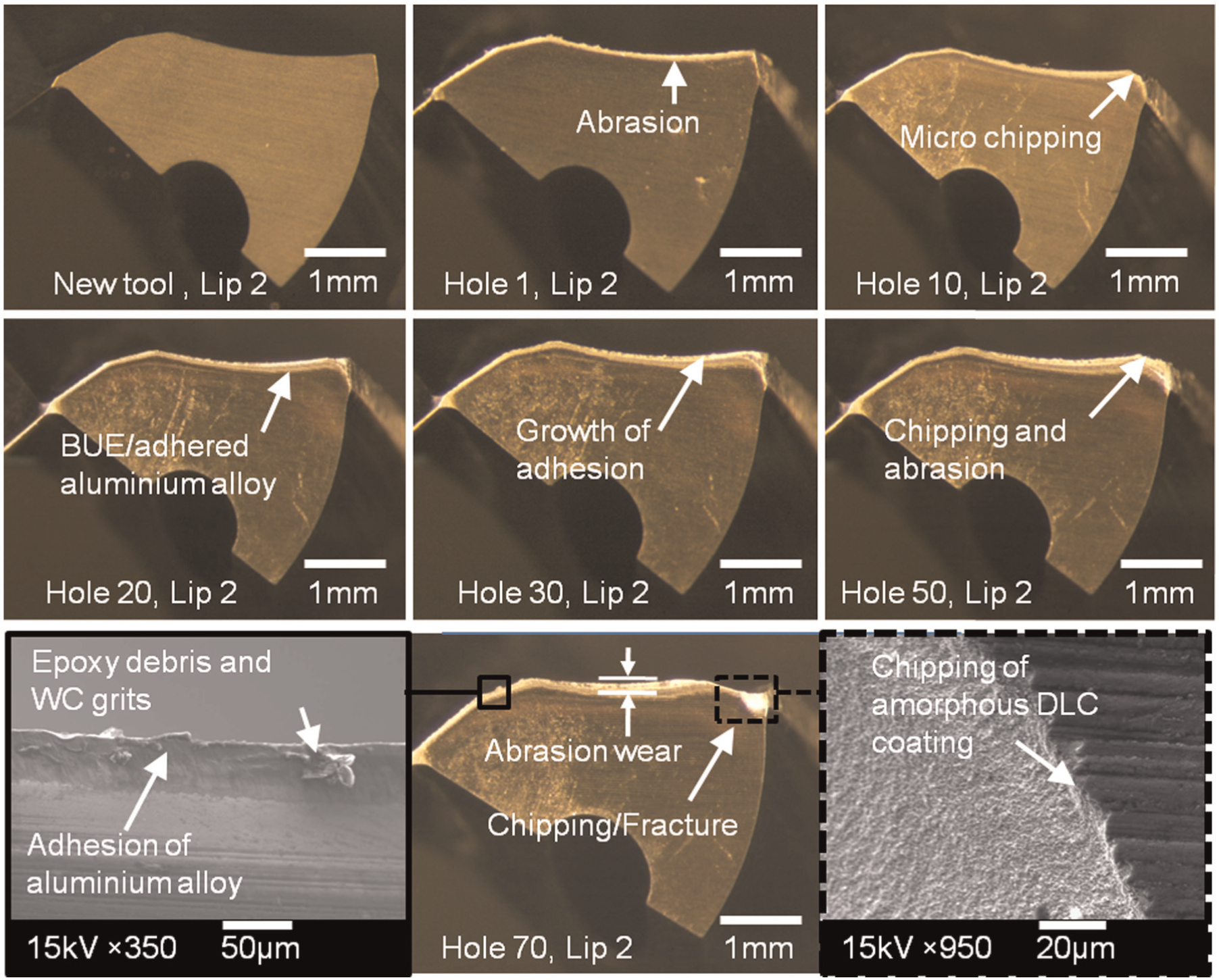
Micrographs of drill wear progression in Test 1.
The wear rate of the DLC-coated drill used in Test 3 accelerated considerably as feed rate was increased to 0.15 mm/rev, with average flank wear after 70 holes measuring ∼255µm. In contrast to Test 1, both abrasion and adhesive wear mechanisms were apparent immediately after commencement of the experiment (see Figure 5). The build-up of Al workpiece material initially concentrated at the chisel edge region but subsequently extended over the cutting lips and peripheral corners as machining progressed. Wear on the drill flank face and adhered material increased steadily and corresponded with the rapid rise of thrust force and torque detailed previously in Figure 3. Signs of micro-chipping on the cutting lips at the drill corner were prominent after 50 holes, which was partly due to the relatively high thrust force in the Ti section which reached ∼1800 N. Several reasons were thought to be responsible for tool failure after 70 holes, not least the cyclic variation of thrust forces acting as the drill travelled through the stack (maximum of ∼2500 N in Ti and minimum of ∼500 N in CFRP layer over ∼3 s duration), which may have induced a low-cycle fatigue condition which triggered brittle fracture. 13 In addition, fracture/removal of adhered workpiece material would have further compromised the strength/integrity of the drill corner. Subsequent SEM evaluation of the fractured area revealed the presence of coalescent voids near the rake surface together with striations indicative of fatigue failure from cyclic loading (see Figure 5). The fine band structure of the latter propagating through the WC matrix is characteristic of a brittle fracture mechanism. 13
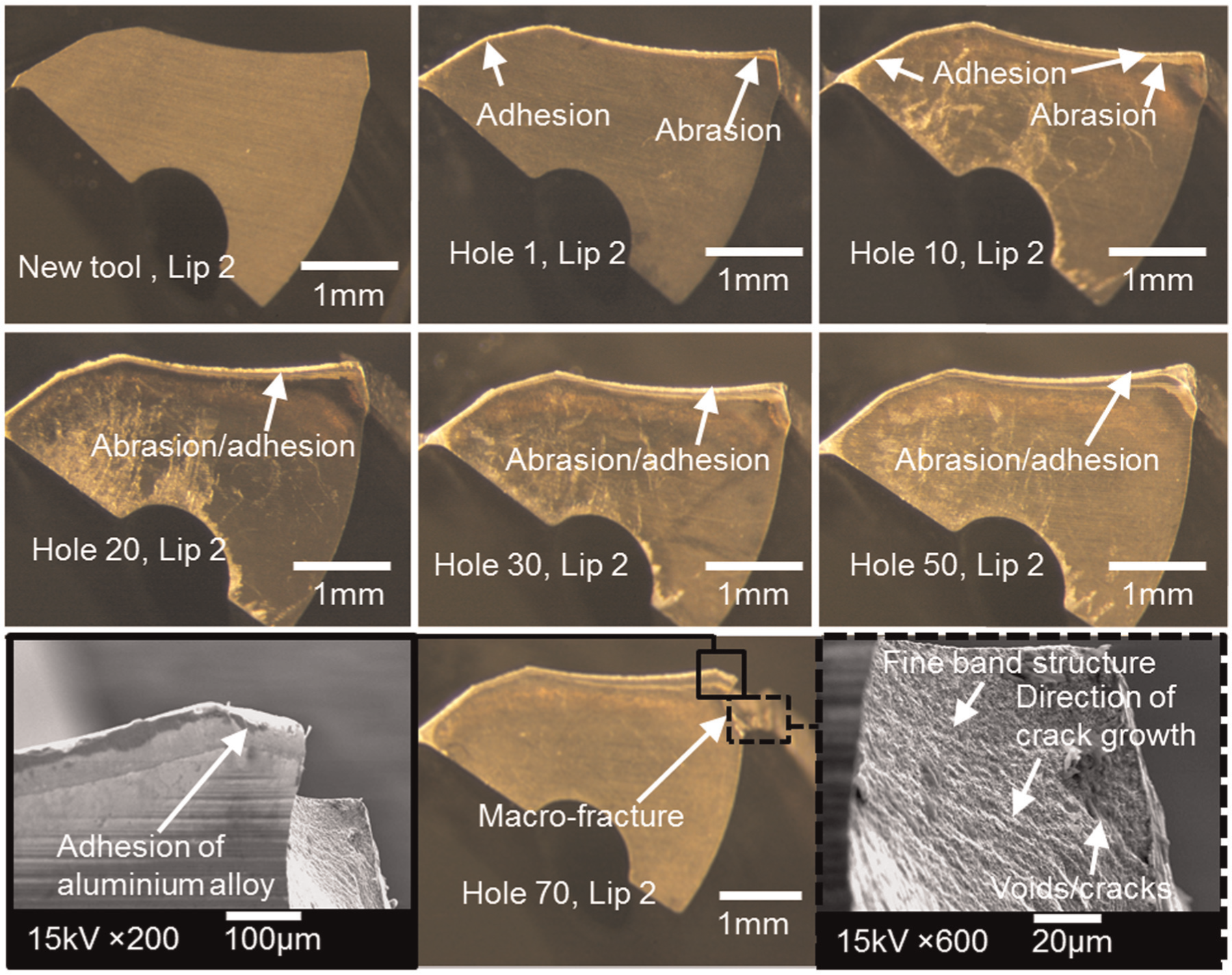
Micrographs of drill wear progression in Test 3.
Figure 6 details wear progression of the CVD diamond-coated drill utilised in Test 2. Adhesion of workpiece material on the cutting edge was visible after the first hole, while flaking/peeling of the coating was observed after hole 20. Initial delamination of the diamond coating was most acute at the chisel section due to the 120° point angle which provided an area of stress concentration and was therefore subjected to a greater proportion of loading during machining. Subsequent failure of the CVD diamond layer was likely triggered by a critical accumulation of shear stress/strain at the bond interface caused by the dissimilar stiffness modulus between the coating (1000 GPa) and drill substrate (580 GPa) material. Despite extensive loss of the coating layer, there was no significant increase in thrust force and torque detected even after 50 holes. This suggests that successive wear of the drill from abrasion was gradual up until hole 70, where fracture of the chisel edge occurred. Further SEM analysis of the exposed carbide region highlighted the presence of micro-cracking at several locations on the worn cutting lips. However, unlike experiments involving the DLC-coated drills, the corners of the CVD diamond-coated tool remained intact at test cessation, although traces of adhered Al material were prevalent.
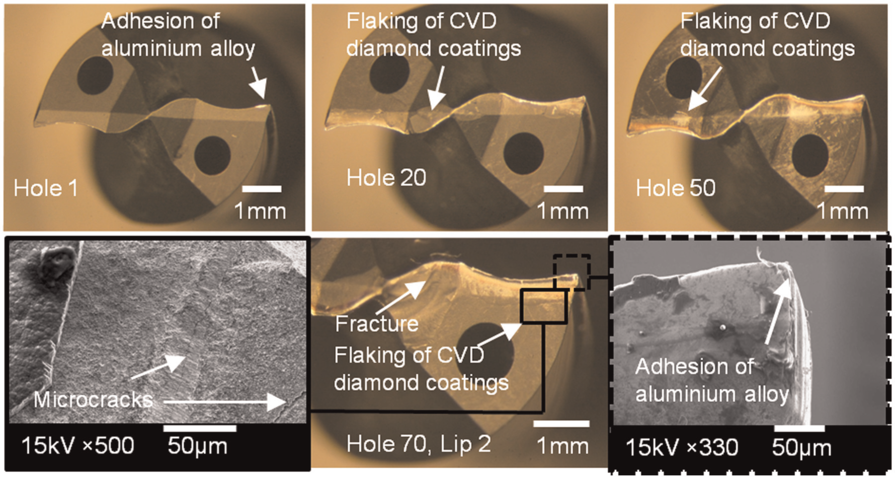
Micrographs of drill wear progression in Test 2.
Hole accuracy
Figure 7(a) details the average diameter of the last hole drilled in each individual material layer and the overall stack for all tests. The CVD diamond-coated drills produced the best results when operating at 0.08 mm/rev feed rate, with measured diameters ranging from 6.34 to 6.40 mm over the test duration of 70 holes. This was within the typical hole diameter tolerance of 6.38 ± 0.04 mm for aerospace applications. In contrast, holes machined with the DLC-coated drills were marginally oversized particularly in the Ti section, with the overall diameter moving out of tolerance after 30 and 10 holes when employing feed rates of 0.08 and 0.15 mm/rev, respectively. The superior performance of the CVD-coated drills was attributed to the two-stage point design, which provided the drill with improved ‘self-centring’ capability, thereby reducing tool deflection or run-out. Figure 7(b) shows average hole cylindricity over the entire stack together with corresponding out-of-roundness measurements for each of the individual Ti, CFRP and Al sections. The test undertaken with the DLC-coated drill at 0.08 mm/rev produced holes with an average cylindricity of 140.6 µm, while increasing the feed rate to 0.15 mm/rev reduced this value to 77.4 µm. Hole cylindricity further improved when utilising the CVD diamond-coated tool at 0.08 mm/rev, with an average recorded value of 65.7 µm.
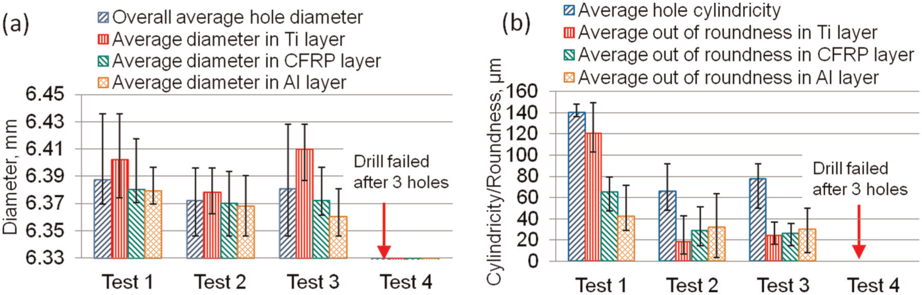
Average (a) diameter and (b) cylindricity and out of roundness of holes over test duration.
Figure 8 details the three-dimensional (3D) hole profiles evaluated at hole 70 in Tests 1–3. The holes machined in Test 1 typically exhibited a ‘three-lobed’ cross section, as shown in Figure 8(a). This suggests that low-frequency vibration in the form of radial tool deflection was probably induced when utilising the DLC-coated drill under these conditions. This would also explain the comparatively high out-of-roundness levels (average of up to ∼120 µm in the Ti section) seen previously in Figure 7(b). When employing the CVD diamond-coated drill in Test 2, the average out of roundness did not exceed ∼30 µm in any of the material sections, which was reflected in the circular cross section of the hole illustrated in Figure 8(b). The hole profile, however, was tapered towards the exit location, as the tendency for drills to wander diminishes as it moves deeper into the stack. 14 Increasing feed rate of the DLC-coated drill to 0.15 mm/rev in Test 3 resulted in similar hole roundness values as in Test 2, which were on average ∼100% better compared to Test 1. In addition, the change in feed rate suppressed formation of the three-lobed profile, although a ‘bell mouth’ shape at the top of the hole was prevalent (see Figure 8(c)). This was possibly due to the greater wear/flattening of the chisel edge, which exacerbated ‘wander’ of the drill from the centre of the hole as it entered the stack.
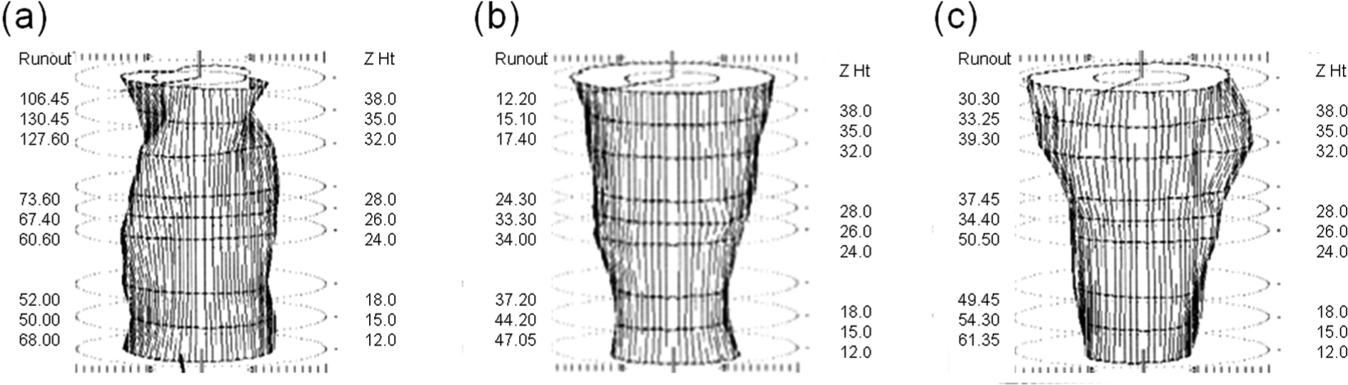
Hole cylindricity measurements and profile at hole 70 in (a) Test 1 (cylindricity = 141.30 µm), (b) Test 2 (cylindricity = 49.40 µm) and (c) Test 3 (cylindricity = 90.30 µm).
Burr formation
The first holes produced using new drills were found to be virtually burr free in all tests irrespective of feed rate or point geometry/tool coating, with the onset of burr formation observed as machining progressed. Figure 9(a) details the maximum burr height measured at both the hole entry and exit locations of the metallic sections (Ti and Al) over the duration of each trial. With the exception of hole exit on the Al section in Test 1, burr height did not exceed ∼0.11 mm, even at test cessation. In all cases, the burrs generated were classified as uniform (Type II), 15 with cross sections similar to that shown in Figure 9(b). When operating at a feed rate of 0.08 mm/rev, the maximum burr size at the exit position of the stack (Al layer) was over 4 times larger when using the DLC (0.38 mm) compared to the CVD diamond-coated drill (0.09 mm). This was attributed to enlargement of the corner chamfers and greater wear of the cutting edge in the former due to chipping/fracture. The result was increased plastic deformation/ploughing of the aluminium workpiece material immediately prior to drill exit together with shifting of the pivot point away from the hole, leading to larger, elongated burrs. 16 Increasing feed rate to 0.15 mm/rev in Test 3 significantly reduced burr height due to shorter contact time between the drill corner and workpiece material, which promoted greater shearing/fracture of the chip. In contrast, relatively small burrs were observed at the exit and entry of the Ti and Al sections, respectively, in all the holes evaluated. This was due to the CFRP plate acting to restrain the development and propagation of burrs. 17
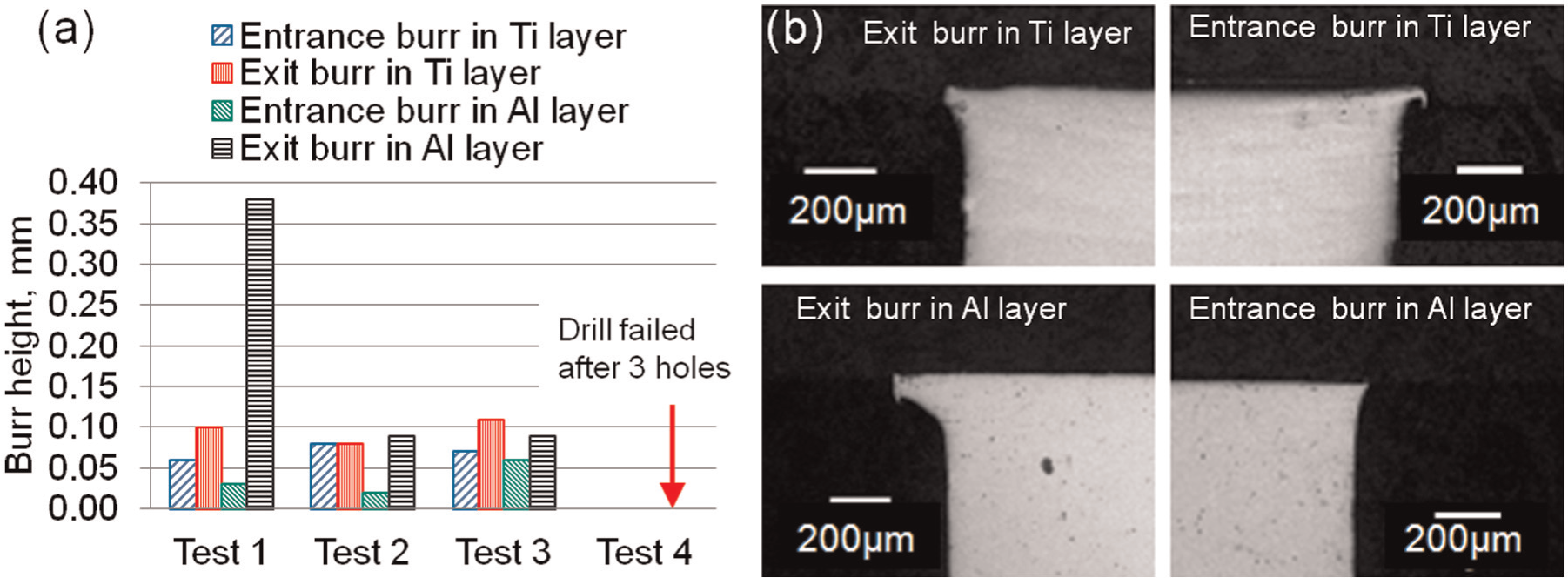
(a) Maximum entry and exit burr height in Ti and Al sections measured over test duration and (b) cross-sectional micrographs of entry and exit burrs in Ti and Al sections for Test 1 at hole 70.
Conclusion
Wear of the DLC-coated drills at a feed rate of 0.08 mm/rev was initially dominated by abrasion, with increasing levels of workpiece adhesion and micro-chipping evident as machining progressed. Tool failure occurred in the form of drill corner fracture due to attrition from the repeated cycle of adhered material build-up and removal, resulting in plucking of the coating and weakening of the substrate material.
The primary wear mode of the CVD diamond-coated drill at 0.08 mm/rev was premature flaking/delamination of the coating, particularly in the vicinity of the chisel section which finally resulted in fracture after 70 holes. This was most likely due to the double-point design, which concentrated the thrust forces over a relatively small area.
Both thrust force and torque in the titanium layer increased significantly when machining at the higher feed rate of 0.15 mm/rev using the DLC-coated drill, with values of ∼2500 N and 725 N cm recorded after 70 holes. This was ∼150% and 60% higher than corresponding levels at 0.08 mm/rev, respectively.
The failure mechanism of the DLC-coated drill when operating at 0.15 mm/rev was brittle fracture due to a low-cycle fatigue condition. This was most likely induced by the large variation in thrust forces (up to ∼1000 N) acting on the drill as it moved through the titanium and CFRP/Al layers of the stack.
Despite severe flaking/chipping, the CVD diamond-coated drill produced superior hole quality coupled with reduced burring compared to the DLC-coated tools due to the two-stage point design and lower geometrical damage at the peripheral corner.
Footnotes
Declaration of conflicting interests
The authors declare that there is no conflict of interest.
Funding
This study received the support of GKN Aerospace, Seco Tools and Element Six Ltd through the provision of financial support, tooling and workpiece material.