
Abstract
The adhesion of wear-resistant diamond coating deposited on titanium was weakened by the porous titanium carbide interlayer, which was formed before film growth. In order to enhance substrate-coating adherence, a new pretreatment method was presented: Ti substrates were carbonized by hot filament chemical vapor deposition system, and then the carbonized substrates were ultrasonically vibrated using diamond micro-powder suspension. Diamond coatings were deposited by hot filament chemical vapor deposition as well. The effect of carbonization time on adhesion was investigated. The carbonized substrates and the interface between diamond coatings and substrates were characterized. The results showed that as the carbonization time increases, porous structures and cracks appear and increase on the surface of the substrate. The carbonized substrates possess high surface energy and thus the nucleation is promoted. After deposition, a dense and thin titanium carbide was observed. Ultrasonic after carbonization pretreatment can significantly enhance the adhesion of Ti-based diamond coatings by promoting nucleation and suppressing the formation of porous titanium carbide.
Introduction
Titanium is a well-known material and has been applied in many fields such as aerospace, biomedicine, and chemical engineering for its low density, high tensile strength, and high corrosion resistance.1,2 However, the main disadvantage of titanium is its poor tribological performance, which greatly limits the application of titanium. 3 The wear resistance of titanium can be significantly improved by depositing a wear-resistant diamond coating by chemical vapor deposition. 4 Diamond coating has high hardness, excellent biocompatibility, and corrosion resistance, which extend the application prospects of titanium in high-tech fields.5–9
Good substrate-coating adherence is the basis of coating performance, and the service life of the coating is increased by enhancing the adherence as well. However, diamond coatings on Ti substrates have poor adherent properties for their large thermal expansion coefficients mismatch. There is high residual stress after cooling stage, which leads to coating peeling off. 10 Besides, titanium, a strong carbide metal with a large carbon diffusion coefficient, easily reacts with the adsorbed carbon and forms a TiC layer in the early stage of diamond deposition. 11 The TiC layer formed in this stage makes it easier for the diamond nucleation. But the substrate-coating adherence will be weakened by the TiC layer, which can be porous and as thick as tens of microns. 12 Besides, the formation and increase in thickness of the TiC layer led to a decrease in the wear and scratch resistance. 13
The hot filament chemical vapor deposition (HFCVD) system is often used to deposit diamond coatings and is the simplest deposition method.14,15 Before deposition, proper pretreatment methods can effectively shorten the incubation period, enhance nucleation, and enhance the substrate-coating adherence.16,17 Sandblasting and ultrasonic vibration are two commonly used pretreatment methods, and the scratches and defects caused by them provide high-energy sites which are beneficial to nucleation. Besides, the diamond powders remaining on and embedded in the substrate surface provide nucleation sites for direct diamond growth. Boron doping is an effective method to suppress the growth of TiC by forming compounds like TixBy or Ti(C, B) and enhance diamond nucleation.18,19 Another method is introducing an interlayer. Several surface interlayers were adopted to improve the substrate-coating adherence such as diamond-like carbon (DLC), 20 Nb, 21 Si, 22 and duplex interlayers such as nitriding and carbonitriding layer. 23 These interlayers serve as a barrier to prevent the Ti substrate from the diffusion of carbon and hydrogen, inhibit the formation of TiC and eliminate the hydrogen embrittlement, promote nucleation, or have median thermal expansion coefficient to reduce the thermal stress. Laser surface texturing is also used to texture substrate, and the substrate-coating adherence is enhanced by the function of anchoring between the textured surface and the diamond coatings. 24 In addition, Li et al. 25 deposited diamond coatings on pure Ti substrate at a moderate deposition temperature; the nucleation density and adhesion strength of diamond coatings were markedly enhanced under a super-high CH4 concentration.
The interlayer technology is effective but relatively costly and complex. As for ultrasonic vibration after sandblasting pretreatment, the formation of porous TiC will change substrate surface morphology; therefore, a part of scratches and defects caused by ultrasonic pretreatment may disappear. A new pretreatment, which is based on the ultrasonic vibration after sandblasting pretreatment, was presented in this article. The substrates were first carbonized for a certain period and then ultrasonically vibrated in diamond suspension. The substrates carbonization and diamond coatings synthesis were carried out using HFCVD. This pretreatment is relatively simple to operate. The effects of different carbonization time on the morphology were studied in this article. The nucleation density on the treated substrate, the carbonized layer after pretreatment, and the deposition were characterized. The substrate-coating adherence was evaluated.
Experimental
Ti sheet with the size of 12 × 12 × 2 mm2 was used as the substrate, and the diamond coatings were synthesized by HFCVD technique. Before carbonization, the Ti substrates were polished with 360- to 1000-grit SiC sandpapers and sandblasted using SiC particles carried by compressed air. Then, the substrates were ultrasonically cleaned in alcohol for 10 min and dried by flowing Ar.
The substrates carbonization was carried out using a HFCVD system. The tungsten filament temperature was kept at 2200°C by Raytek infrared thermometer and the substrate temperature was kept at 800°C by K-type thermocouple. Gas pressure was 1.5 K Pa, total gas flow rate was 400 sccm, and the methane to hydrogen ratio was 3:97. The boron elements were incorporated by trimethylboron (TMB) to further inhibit the formation of titanium carbide and promote nucleation, and the B/C ratio was 4000 ppm. Table 1 shows the different carbonization times applied to each sample. The C1 sample, which was carbonized for 0 min, represents the commonly used pretreatment for comparison. Then, the substrates were ultrasonically vibrated in 50 mL of acetone mixed with 3 g of 0.5-μm-sized diamond powder for 30 min and ultrasonically cleaned in alcohol for 2 min.
Substrate pretreatment of each sample.
The diamond coating nucleation and growth were carried out using a HFCVD system as well. Since the carbonization period was separated from the nucleation period, nucleation stage used the same parameters as the carbonization stage. After 1 h, the methane to hydrogen ratio was reduced to 1.5:98.5 and the gas pressure was increased to 3 K Pa for diamond grown for 6 h.
The surface topography of the carbonized Ti substrates and diamond coatings, the interface of diamond layer and TiC layer, and the cross-section of diamond coating were characterized by scanning electron microscopy (SEM) and energy-dispersive spectrometer (EDS). The composition of the diamond coatings was characterized by micro-Raman spectroscope with the laser wavelength of 532 nm, the exposure time of 6 s, and the accumulation times of 20 times. The contact angle of treated substrates was measured using a contact angle goniometer, and distilled water was used. The surface energy was calculated using the software JC2000D, which was delivered in combination with the contact angle goniometer. The adhesion of the diamond coatings were evaluated by Rockwell C indentation test using a 588 N load.26–28
Results and discussion
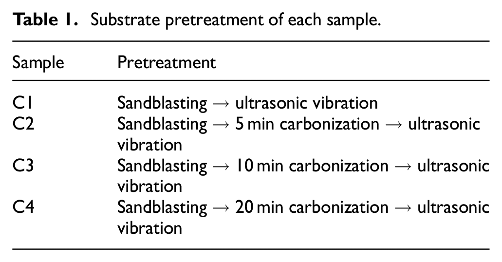
Figure 1(a) shows the SEM images of C1 sample. A dense, well-faceted, and polycrystalline diamond coating with diamond grain size of about 1.5 μm can be observed. The morphology features of rough sandblasted substrate surface can be observed, and the diamond forms a continuous film on the rough substrate surface with no substrate exposed. The phase composition of diamond coating was determined by Raman measurement, and the Raman spectra of diamond deposited on C1 sample were shown in Figure 1(b). Peak at 1310 cm−1 verified the diamond phase in films, and the peak shift from 1332 cm−1 represents the standard diamond phase is mainly due to the effect of boron doping and internal stress. Peaks at 479 and 1220 cm−1 originate from the Fano interaction, 29 meaning that the boron element was successfully doped. Sun et al. 30 added high concentration of boron in the reaction compartment at the initial stage to inhibit the formation of TiC interlayer. A wide week peak around 1580 cm−1 originates from the nondiamond carbon phase (amorphous and graphitic). This Raman spectrum is typical for a boron-doped diamond film.
(a) SEM image and (b) Raman spectra of diamond deposited on C1 sample.
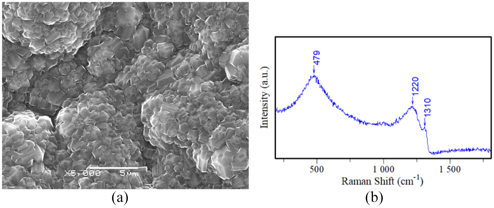
Figure 2 shows the Rockwell indentation morphology and the porous TiC layer. Large pieces of peeling can be observed around and in the hole of indentation, which indicates the poor adherence of C1 sample, as shown in Figure 2(a). Figure 2(b) shows the boundary of coating and peeling off area of Figure 2(a), and Figure 2(c) shows the cross-section image. Figure 2(b) and (c) reveals the existence of the porous TiC interlayer, as published in early literature. 31 Holes can be observed from both the front and the side in Figure 2(b) and (c), scattered randomly in the interlayer with a size ranging from 1 to 5 μm. Crack caused by Rockwell indentation test is observed on diamond coating. Considering the high hardness and loose structure of titanium carbide, the interface between the substrate, titanium carbide, and diamond coating and the interior of the titanium carbide may fracture and lead to coating peeled off under external force and large thermal stress. This TiC interlayer with a thickness of more than 20 μm damages the adherence significantly. 32 The adherence of diamond coating deposited on Ti can be enhanced by suppressing the formation of titanium carbide or promoting the formation of dense titanium carbide. 18
SEM images of C1 sample: (a) Rockwell indentation, (b) coating and coating peeling off area that substrate exposed, and (c) cross section.
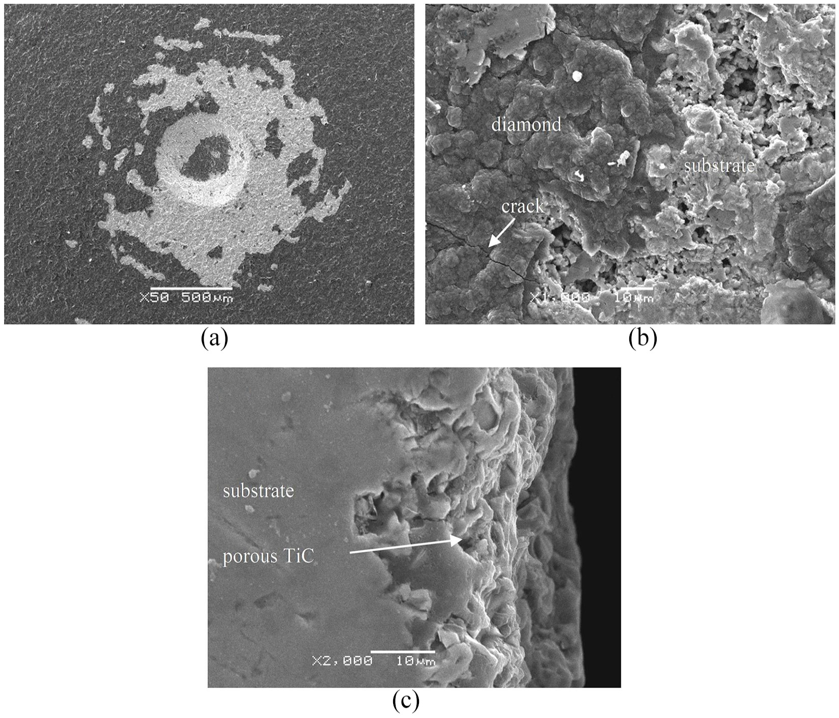
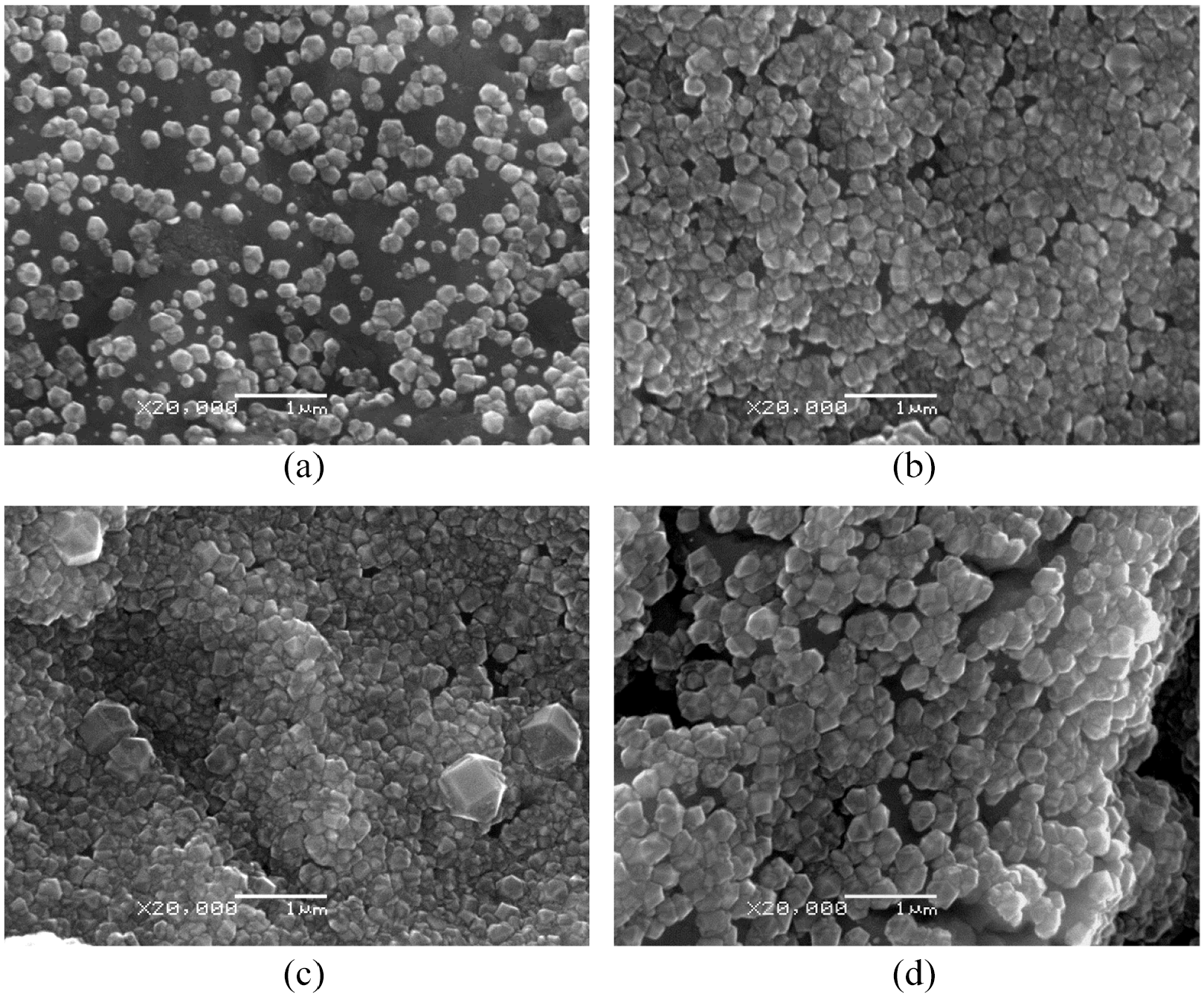
Figure 3 shows the morphologies of substrates under different carbonization times before diamond coatings deposition. Figure 3(a) and (b) shows the typical sandblasted substrate surface, a rough and disordered structure formed by impact and scraping of abrasive grains, and substrate can be observed. As shown in Figure 3(c) and (d), few shallow pits and the porous structures were observed on the sandblasted substrate surface when carbonization time was 5 min. The rough surface caused by sandblasting still exists, meaning that a short carbonization time can only change the morphology of the substrate to a small extent. With carbonization time increased to 10 min, more porous structures were observed in Figure 3(e) and (f). Those porous structures with a size less than 1 μm are formed by the reaction between Ti substrate and absorbed carbon. When the carbonization time continues to increase to 20 min, more holes with larger size were observed. Through the comparison of Figure 3(a) and (g), the morphology before and after carbonization has changed greatly, indicating that the formation of TiC can change the morphology of the substrate. Most of the porous structures appeared in the valley of the surface and look like honeycomb. Besides, a few grown crystals with a size of about 0.5 μm can be observed in Figure 3(g) and (h); this is because the surface has saturated with carbon and nucleation begun. Micro-cracks can be observed in Figure 3(e) and (g), which is mainly caused by the formation and rupture of brittle titanium hydride phases, consistent with Li’s research. 12 More and longer micro-cracks can be observed in Figure 3(g) because C4 sample was treated longer and more titanium hydride phases were formed. With the increase of carbonation time, the area of the porous structure increases, the size of the hole increases, and the number of cracks increases. Finally, nucleation begun. Guo et al. 11 found that the carbonized substrate has a porous surface. Thus, carbon concentration on C3 sample surface was close to saturation but not exceeded it.
SEM images of substrates under different carbonization times: (a) 0 min, (c) 5 min, (e) 10 min, (g) 20 min. (b), (d), (f), and (h) are high resolution images of (a), (c), (e), and (g), respectively.
Diamond nucleation density is related to surface energy, and high surface energy facilitates diamond nucleation. 33 In order to correlate with subsequent nucleation density measurements, the surface energy of substrate before and after carbonization was measured. Figure 4 shows surface energy of each samples. C1 sample, which was sandblasted, possesses the lowest surface energy of 41.348 mN/m, indicating poor surface treatment capability of sandblasting. Relatively large deviations indicate the poor reproducibility of the sandblasted surface. All the three carbonized samples have higher surface energy than C1 sample, which means that changes in surface composition cause changes in surface energy. Besides, porous structure contributes to increase the surface energy because porous structure is beneficial to increase specific surface area. The highest surface energy of 53.675 mN/m of C3 is presented in Figure 4. C2 sample possesses a slightly lower surface energy of 53.502 mN/m because C2 sample surface has less porous structure than C3. C4 sample possesses a third surface energy of 50.591 mN/m, which may associate with the appearance of diamond grains, and adjacent holes merge into larger ones with the increase in carbonization time, thereby decreasing the specific surface area.
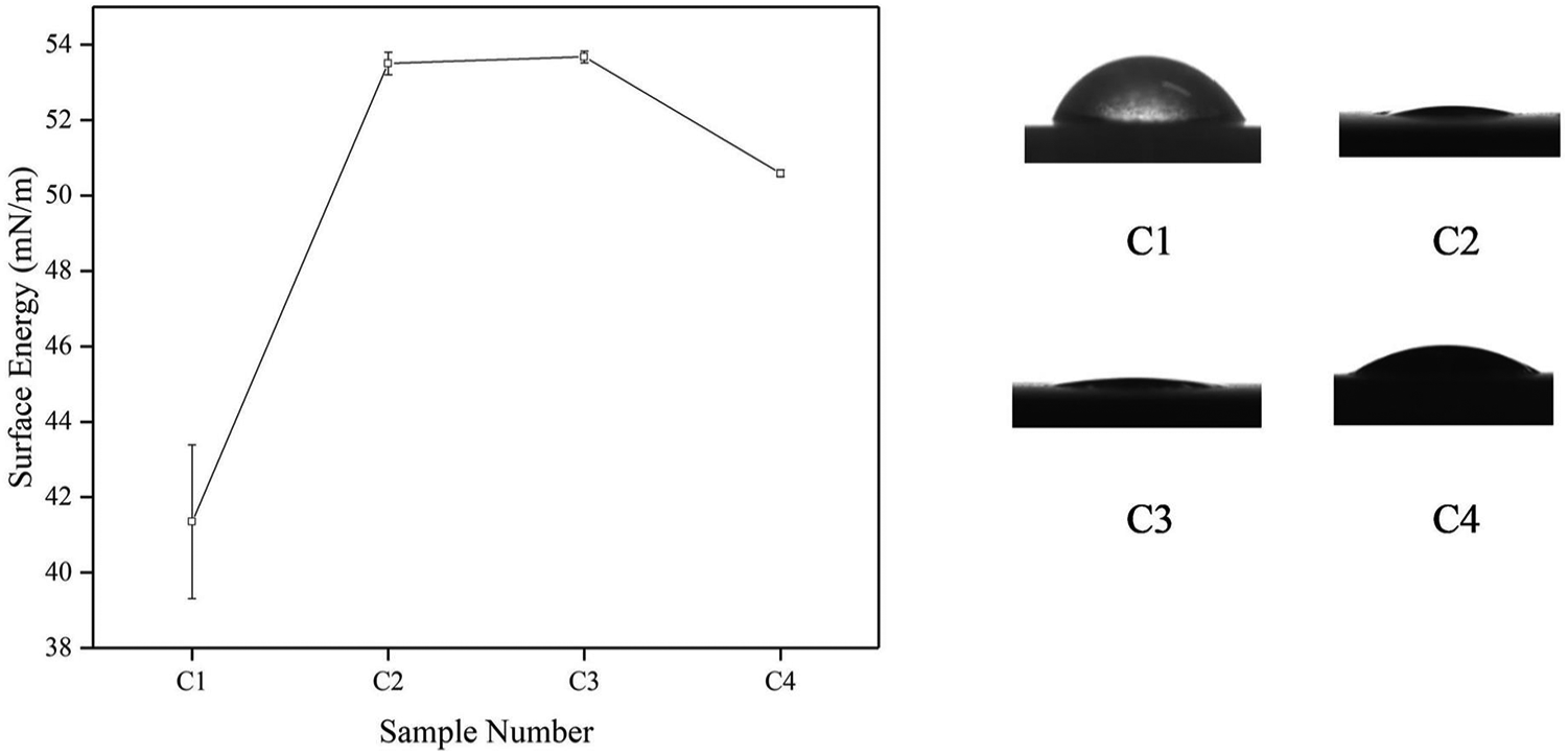
Surface energy of C1 sample, C2 sample, C3 sample, and C4 sample.
Figure 5 shows the diamond nucleation morphologies on each sample under the condition of nucleation parameters for 10 min. As shown in Figure 5, diamond nuclei with size of 200–300 nm are observed on the substrate surface of each sample. The sandblasted substrate, C1 sample has the minimum nucleation density of about 1.43 × 10⁹/cm2, corresponding to its minimum surface energy, as shown in Figure 5(a). All the three carbonized substrates show higher nucleation density. C3 sample has the maximum nucleation density of about 2.68 × 10⁹/cm2, and the surface of C3 sample is almost covered by diamond nuclei, as shown in Figure 5(c). In addition, several large nuclei with the size of 650 nm were only observed on C3 sample surface, which may be caused by the seeding effect, meaning that the porous structure of the C3 surface has appropriate size and thus seeding effect is enhanced. C2 sample has a slightly lower nucleation density about 2.38 × 10⁹/cm2 and C4 sample has a third nucleation density of about 1.65 × 10⁹/cm2. The trend of nucleation density is consistent with the trend of surface energy, confirming that surfaces with large surface energy can provide more energy for diamond nucleation. 33 In Figure 3(h), a very low nucleation density of 2.58 × 10⁷/cm2 is observed on the substrate surface which was carbonized for 20 min, and it can be regarded as the nucleation density of the sample which is first carbonized for 10 min and then nucleated for 10 min while no ultrasonic vibration is applied, because the parameters of carbonization and nucleation are the same. All the nucleation density under different pretreatment parameters is listed in Table 2. Substrates which were only carbonized or ultrasonically vibrated have a low nucleation density while substrates which were ultrasonically vibrated after carbonization show high nucleation density. Thus, it is the combined effect of ultrasonic after carbonization pretreatment that helps to promote nucleation.
SEM images of diamond nucleation on (a) C1 sample, (b) C2 sample, (c) C3 sample, and (d) C4 sample.
Nucleation density after 10 min under different pretreatment parameters.
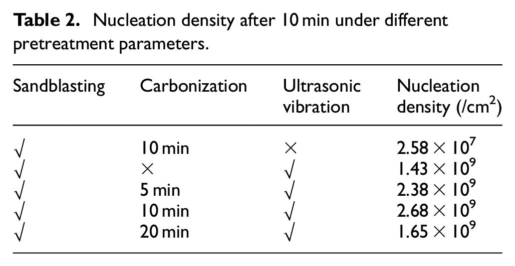
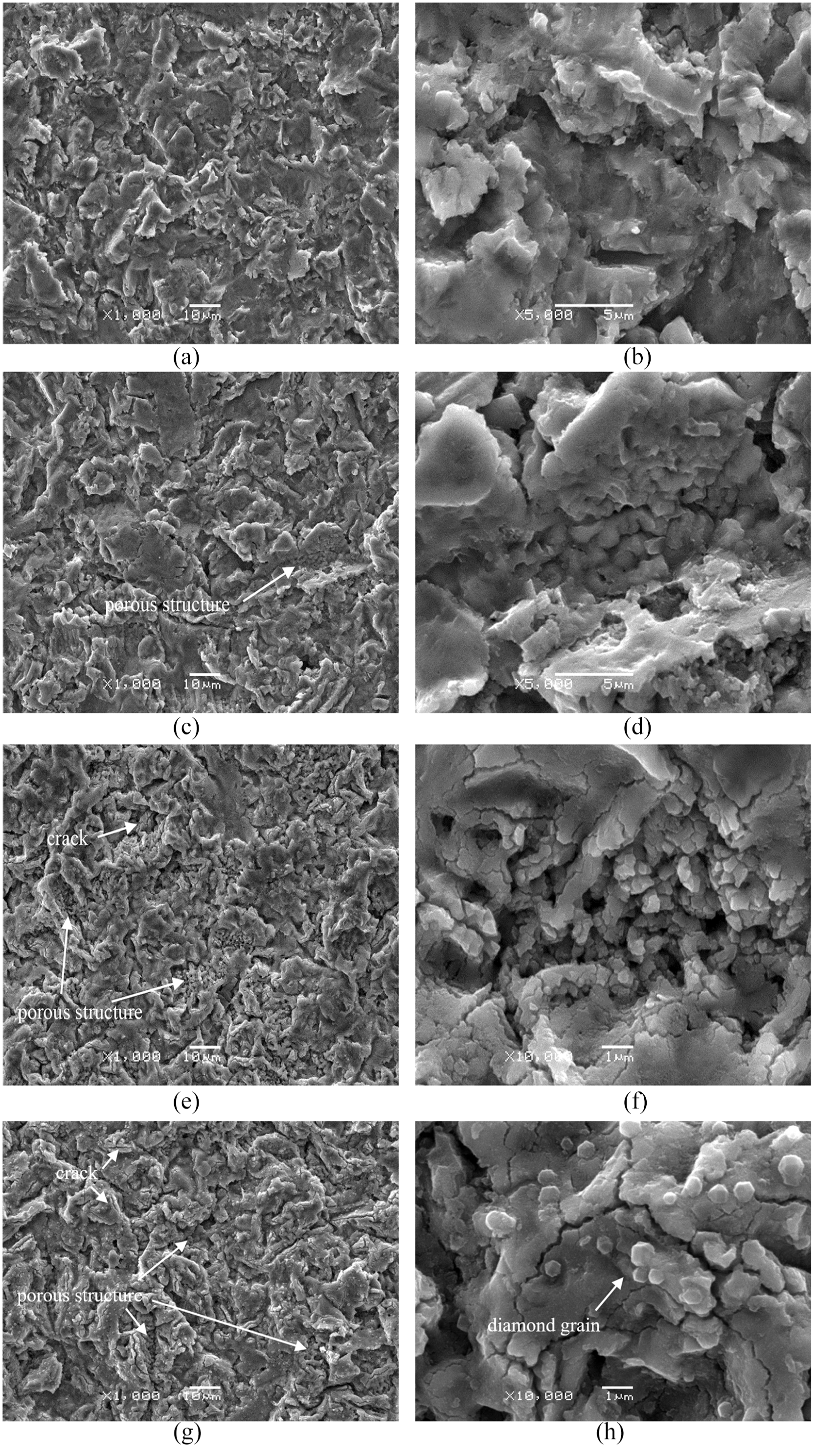
Figure 6 shows SEM images of Rockwell indentation morphology of three carbonized samples. As the carbonization time increases, the adherence first increases and then decreases. Figure 6(a) shows relative medium peeling area, Figure 6(b) shows minimum coating peeling while maximum peeling area is observed in Figure 6(c), which has the consistent trend with the nucleation density. All the three carbonized samples have better adherence than C1 sample, and C3 sample shows best adherence, which means that ultrasonic after carbonization pretreatment helps to improve substrate-coating adherence. Diamond nucleated soon on C3 sample at high nucleation density, and then a dense and continuous diamond films formed quickly, and the seeding effect of ultrasonic vibration process was enhanced by the porous surface; thus, diamond coating on C3 sample shows the best adherence. The carbon concentration on C3 sample surface was already saturation; however, excessive cracks on C4 sample lead to coating peeling off after indentation tests; thus, the poor adherence of C4 is observed. The reason for C3 sample possesses better substrate-coating adherence than C2 sample can be summarized that the carbon concentration on the surface of C2 sample is insufficient, resulting in a lower nucleation density.
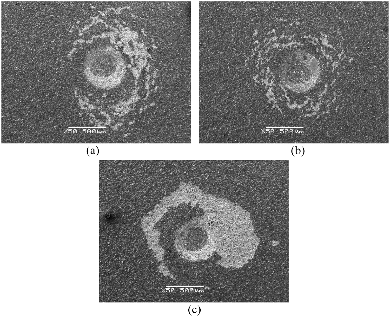
SEM images of Rockwell indentation on diamond coating on (a) C2 sample, (b) C3 sample, and (c) C4 sample.
Figure 7 shows the cross-section images of C3 sample before and after diamond coating deposition, and image of substrate after coating peeling off. In Figure 7(a), a rough structure can be observed, as carbon adsorption and formation of carbide changed the morphology of sandblasted surface. Numerous pits are observed on the surface but no porous structure is observed inside. Adherence property of diamond coating deposited on Ti can be enhanced by suppressing the formation of TiC. 18 Figure 2(b) and (c) shows a thick and porous TiC interlayer while Figure 7(b) and (c) shows significantly different structure. As shown in Figure 7(b), no porous structure is observed, and the surface of substrate after coating peeling off shows dense structure in Figure 7(c). There is no obvious porosity at the interface between diamond coating and substrate as well, meaning that the film and substrate are well contacted. A diffusion depth of about 2 μm of carbon was observed in Figure 7(d), means the formation of a thin TiC.
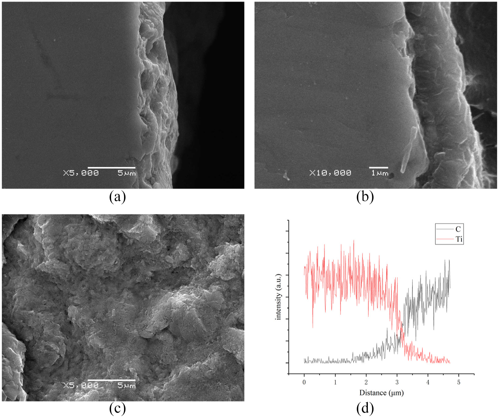
Cross-section images of C3 sample (a) before and (b) after diamond coating deposition, (c) image of coating peeled off and the substrate exposed, and (d) EDS of (b).
High nucleation density is beneficial to enhance adherence by increasing the contact area of substrate and coating. 34 An ultrasonically damaged surface has uniformly distributed defects that facilitate nucleation. However, in the early stage of diamond deposition, the formation of porous TiC will change the morphology of substrate and the number of defects will decrease, resulting in a decrease in nucleation density. By applying ultrasonic after carbonization pretreatment, that is, the substrate was first carbonized and its morphology changed, but the defects caused by subsequent ultrasonic vibration were retained. Besides, proper carbonization time can also enhance the seeding effect. Untreated substrate shows relatively long incubation period while substrate pretreatment is the most effective method for decreasing the incubation period. 35 A quick coverage of the substrate surface by diamond can act as a diffusion barrier to prevent continued carbon penetration. 25 After applying ultrasonic after carbonization pretreatment, carbon absorption and surface defects greatly shorten the incubation period, and a continuous diamond film formed faster under high nucleation density, thereby reducing the contact time of carbon-containing gas and substrate, and ultimately forming a thinner titanium carbide. Therefore, ultrasonic after carbonization pretreatment helps to increase nucleation density and suppress the formation of porous TiC.
Conclusion
Microcrystalline diamond coatings have been deposited on Ti substrate. Uncarbonized samples show poor adherent property and a porous TiC layer with a thickness of more than 20 μm was observed. Adherence and nucleation density of diamond coating on Ti substrate were significantly enhanced by ultrasonic after carbonization pretreatment. The influence of carbonization time of nucleation and adherence was investigated. Carbonized substrate show porous structure and high surface energy which promotes diamond nucleation. With the increase of carbonation time, the area of the porous structure increases, the size of the hole increases, the number of cracks increases, and nucleation begins at 20 min. Long carbonization time results in excessive cracks and short carbonization time results in insufficient carbon absorb, which will not effectively enhance diamond nucleation. Besides, proper carbonization time can also enhance the seeding effect which provides ready-made nucleation sites. Ultrasonic after carbonization pretreatment suppresses the formation of TiC to a certain extent.
Footnotes
Declaration of conflicting interests
The author(s) declared no potential conflicts of interest with respect to the research, authorship, and/or publication of this article.
Funding
The author(s) disclosed receipt of the following financial support for the research, authorship, and/or publication of this article: This research is sponsored by the National Natural Science Foundation of China (No. 51575269), the Six Talent Peaks Project in Jiangsu Province of China (No. ZBZZ-005), and Graduate Student Innovation Base (Laboratory) Open Foundation of Nanjing University of Aeronautics and Astronautics (No. kfjj20180502).