
Abstract
The low thermal conductivity and high chemical reactivity of titanium alloys result in a short tool life in the milling process. This article investigates the performance of polycrystalline diamond tools in the end milling of titanium alloys (Ti6Al4V) by using small customized cutting tools. The relationship between cutting force and cutting parameters was analysed; tool life, tool wear, and causes that lead to tool failure were discussed. To analyse tool wear and cutting temperatures, residual chemical components on the cutting tool were examined with X-ray diffraction method, while surface integrity of cutting tools was inspected based on the images taken by the scanning electrical microscope. Finite element analysis models were developed to simulate the initiation of cracks under different loading cycles. Through cutting experiments, it was found that brittle chipping and fatigue were the two major modes of failure, and feed rate was the dominant factor that causes large cutting forces.
Introduction
Titanium and its alloys are used widely in aerospace industry owing to their excellent mechanical properties. However, the inherent properties of low thermal conductivity and high chemical reactivity of titanium alloys cause poor machinability. They adversely affect tool life, cause premature tool failure, and eventually lead to extremely low machining efficiency.1,2 While the cutting speed for aluminium alloys can be as high as 2500 m/min, it is not uncommon to mill titanium alloys at a speed less than 90 m/min.
Among the factors that contribute to the poor machinability, low thermal conductivity of the material plays the dominant role. The low thermal conductivity of 6.6 W/m K of titanium, which is approximately 1/10 of aluminium,3,4 causes the accumulation of the massive heat generated by shear and friction forces. When the temperature rises to 500 °C or higher, titanium shows strong chemical reactivity with most tool materials.5,6 This makes it unstable during the milling operation and affects both the performance of the cutting tool and the surface quality of the workpiece.7–9
Extensive research on the machining of titanium had been conducted in the past decade, but a little improvement in the productivity has been achieved due to the lack of appropriate cutting tools. Tungsten carbide and cubic boron nitride (CBN) tools have been used in milling titanium alloys with reasonable satisfaction at low cutting speed of less than 90 m/min. 10 However, when they are applied at high cutting speed (larger than 100 m/min), the tool life becomes unacceptably short. According to our previous research, 11 the longest tool life achieved was 0.32 h when the material removal rate (MRR) was 1069.4 mm3/min and 7.57 h when MRR was 76.3 mm3/min. In many cases, the tool lasted for only a few minutes. With the increased utilization of titanium alloys in aerospace, medical, and automotive industries, there is a pressing need for new cutting tools to improve the productivity.
Diamond is one of the hardest materials in the world. Polycrystalline diamond (PCD) is made by sintering together diamond particles of 1–30 µm in the presence of a cobalt catalyst to produce an inter-grown mass of diamond grains by applying high temperature and pressure. The significant hardness and the excellent thermal conductivity 12 make PCD the most advantageous tool material for the machining of titanium alloys.
Recently, PCD tools have been successfully used in the turning of titanium alloys. Ezugwu et al. 13 studied the surface integrity in turning Ti6Al4V alloy with PCD tools using conventional and high-pressure coolant supplies. Micrographs of the machined surfaces showed that micro-pits and redeposited work material were the main damages to the surfaces. Da Silva et al. 14 investigated the behaviour of PCD tools in turning Ti6Al4V alloy at high-speed conditions using high-pressure coolant supplies. They found that the increase in coolant pressure tended to improve tool life and reduce the adhesion tendency. By studying tool wear of PCD inserts in turning Ti6Al4V, Schrock and Kwon 15 found the evidence of phase transformation in turning titanium material and concluded that a significant difference in wear existed between two different tool materials at low cutting speed; the wear was a result of the transition from alpha to beta phase in the titanium workpiece material. This conclusion is different from that made by Koenig and Neises. 16 Koenig and Neises found that the binder phase and particle size of PCD were the two factors that determined the tool wear.
In addition to turning operations, PCD has also been applied in the milling of titanium alloys but with tools of relatively big dimensions. In 1998, Kuljanic et al. 17 investigated the possibility of applying PCD in end milling with a tool of 32 mm in diameter. A tool life of 381 min was achieved while the cutting speed was 110 m/min and feed rate was 0.125 mm. By using an end milling tool of 32 mm in diameter, Nurul Amin et al. 18 achieved the MRR of up to 59.87 mm3/min while the tool life was almost two times longer than that of WC–Co milling cutters. In order to analyse the wear mechanisms of PCD tools, Li et al. 19 conducted a series of cutting tests using an end PCD mill of 125 mm in diameter and found that PCD tools exhibited relative small edge chipping and flank wear at cutting speed of 250 m/min, and cutting speeds around 250 m/min were the best range for PCD tools when machining Ti6Al4V titanium alloy. Similar research has also been conducted by Ota et al. 20 and Oosthuizen et al. 12 The PCD tool was found to have excellent flank wear resistance compared with conventional cemented carbide tools, and unprecedented high-speed cutting became possible by use of PCD tool with an application of high-pressure coolant.
Surface quality of titanium workpiece is another issue that has been addressed in the application of PCD tools. Oosthuizen and Akdogan 21 investigated the material diffusion in high-speed machining of titanium alloys. Their result shows that carbide and titanium were found as the evidence of diffusion. More recently, by using a 125 mm in diameter end milling tool, Li et al. 22 found that surface quality of Ti6Al4V alloy was sensitive to the variation in cutting speeds.
Although plenty of research has been performed in the machining of titanium with PCD tools, most of the research is focused on the turning process or the milling process but with big cutting tools (more than 10 mm in diameter). So far little research has been conducted in the application of small milling tools. This article investigates the performance of PCD milling tools in milling of titanium alloys (Ti6Al4V) by using customized cutting tools of 6 mm in diameter. Surface quality and wear mechanism of the tool were analysed. The relationship between cutting parameters and cutting force was discussed based on experimental data collected in the cutting tests. By applying X-ray diffraction (XRD) on failed tools, cutting temperature in end milling was examined and chemical components were investigated. Surface quality of PCD tools was examined by using Philips XL 30 scanning electron microscope (SEM). Causes leading to tool failure were discussed and simulated by using finite element analysis (FEA) models.
Experimental set-up and methodology
PCD cutting tool and workpiece
To investigate the effects of geometric parameters of PCD tools in the end milling process, customized PCD tools of 6 mm in diameter with special tool geometries were fabricated (Figure 1). The detailed parameters of the tools are shown in Table 1. The fabrication of the PCD tools was carried out in three steps: (a) cut PCD blanks into small inserts, (b) braze the inserts on a carbide substrate, and (c) grind and sharp the cutting edges into the required dimension and surface finish. Since diamond is the hardest material in the world, the cutting and grinding processes (a) and (c) are very difficult. Wired electric discharge machining (W-EDM) was used to cut small PCD inserts from a large blank, and electric discharge grinding (EDG) was employed to grind the tool geometries on the brazed tool surface to produce the desired PCD cutting tools.
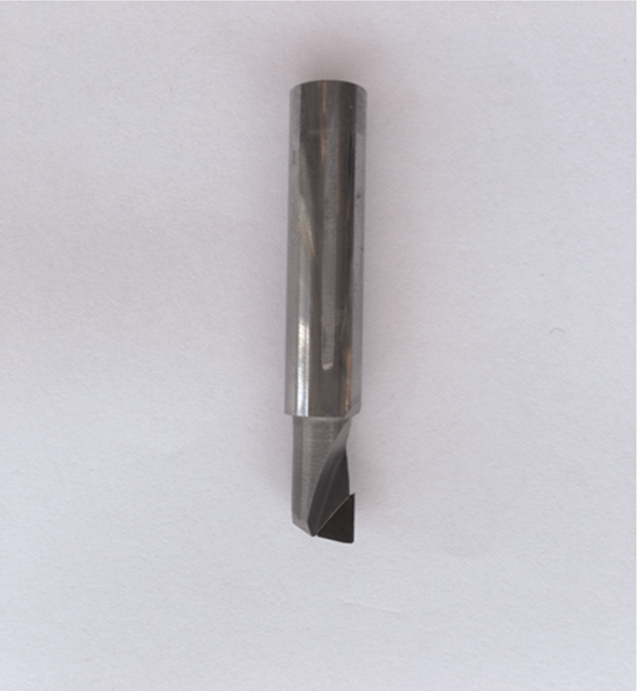
Single-tooth PCD tool.
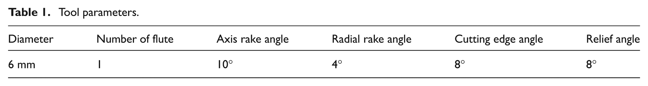
Tool parameters.
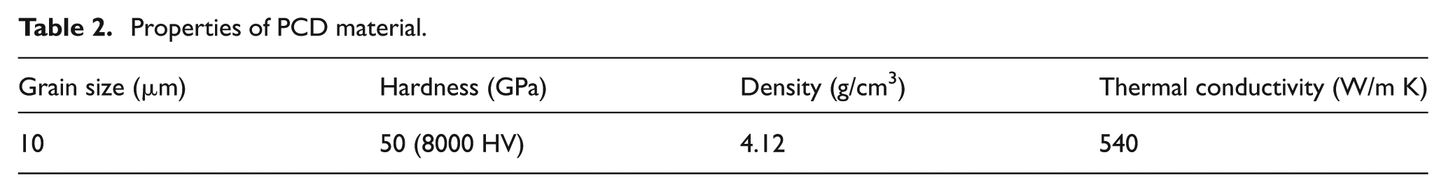
Different PCD materials may demonstrate different performances due to the difference in grain size and the proportion of binding material (cobalt) and diamond particles. The PCD material used in this research was CTB010 made by Element Six. The grain size is 10 µm. Its properties are shown in Table 2. 11 This type of PCD is suitable for applications of super-finishing, finishing, and general purpose machining. In order to investigate the wear of the fabricated PCD tools, surface quality of the new PCD inserts was examined before the milling process (Figure 2). It can be seen that the cutting edge is sharp and the surface is smooth.
Properties of PCD material.
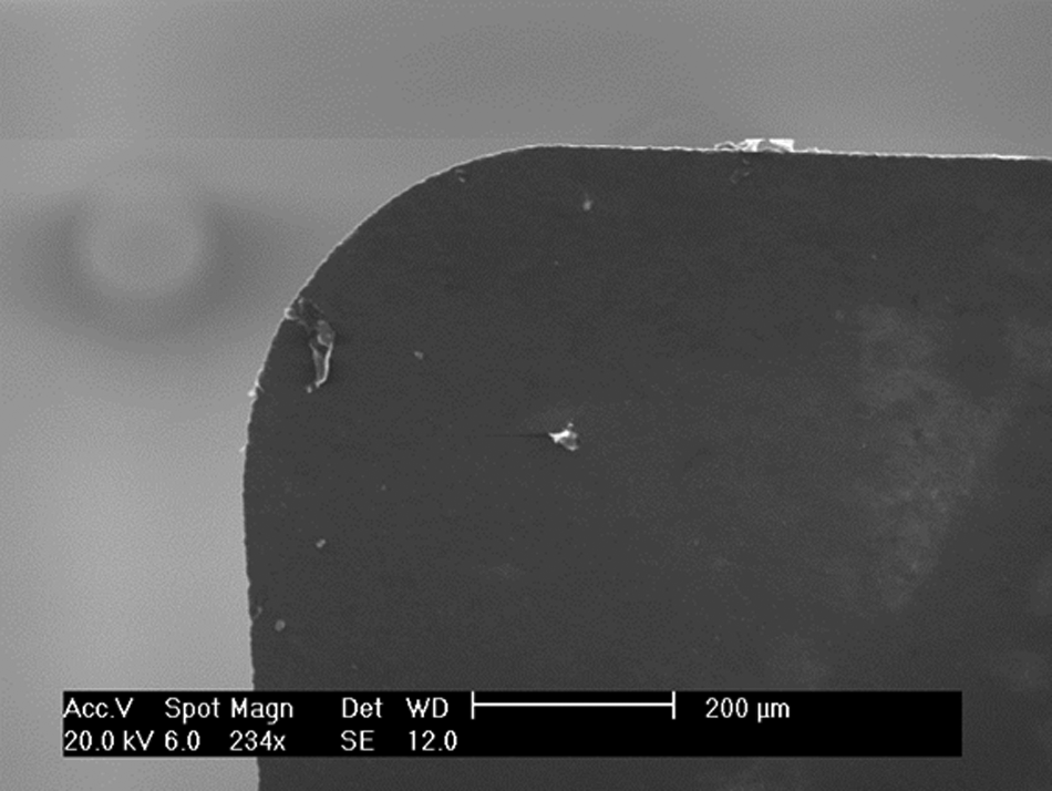
Surface quality of a new PCD insert.
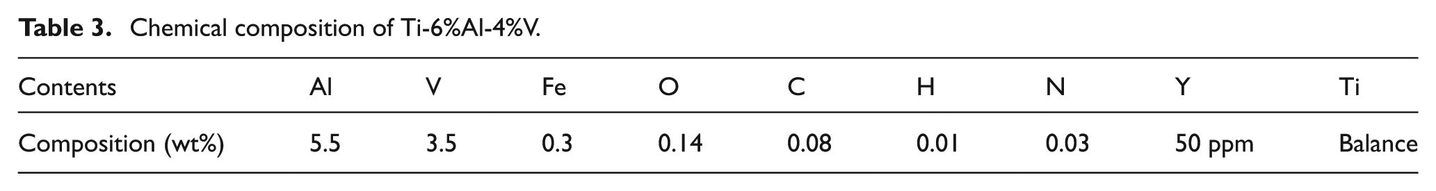
The workpiece is Ti-6%Al-4%V (Ti6Al4V). This is an ‘Alpha + Beta’ type of titanium alloy. It is widely used in aerospace industry and has demonstrated superior overall performance. The chemical composition and mechanical properties of Ti6Al4V are illustrated in Tables 3 and 4, respectively.5,6
Chemical composition of Ti-6%Al-4%V.
Mechanical properties of titanium alloys.
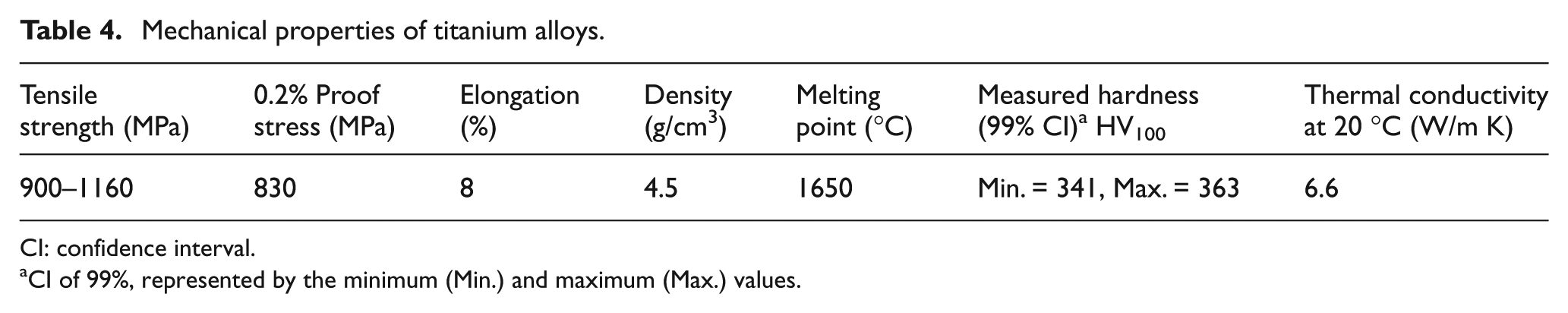
CI: confidence interval.
CI of 99%, represented by the minimum (Min.) and maximum (Max.) values.
Experimental set-up and machining parameters
The cutting experiments were carried out on a four-axis Haas milling machine. Signals of cutting force were collected through an eight-channel dynamometer (Kistler 9257B) installed underneath the workpiece. The coupler used was a six-channel charge amplifier (Kistler 5070). The force signal was recorded via data acquisition (DAQ) card (6036E; National Instruments). The set-up of the experimental system is illustrated in Figure 3. To reduce the effects of noise factors, the tool paths used in the cutting tests were straight lines along the edge of the workpiece.
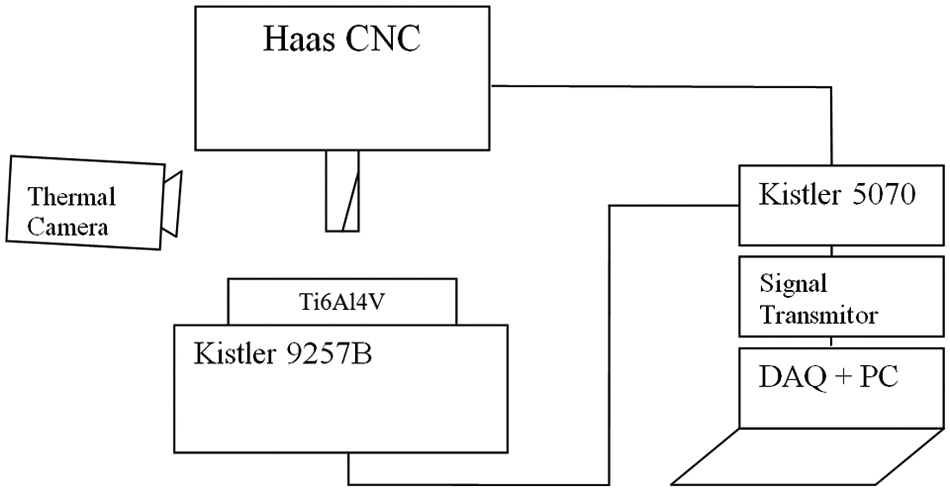
Milling system set-up.
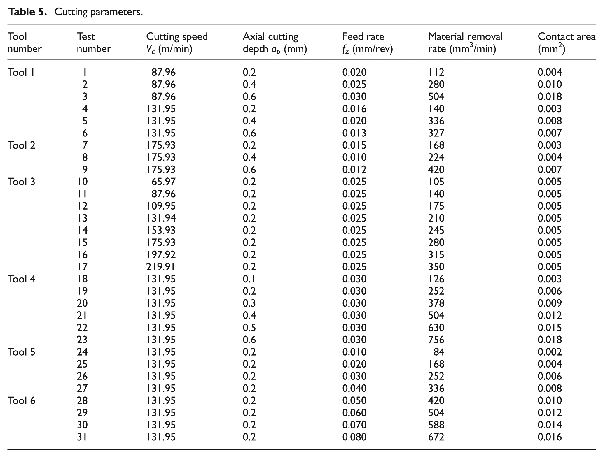
It is understood that three machining factors may affect the surface quality and machining efficiency: cutting speed, feed rate, and axial cutting depth. In the experiment, a total of 31 tests were carried out, and the cutting parameters applied in the experiment are listed in Table 5. The symbols Vc, ap, and fz are cutting speed, axial cutting depth, and feed rate, respectively. To eliminate the effect of tool wear on cutting force and surface quality of workpiece, six new tools that had the same geometrical parameters and grain size were used in this experiment. The radial cutting depth is 3.5 mm, and flooding cooling was applied.
Cutting parameters.
Results and discussion
Cutting force and cutting pressure
Dynamic cutting force is the major cause of tool wear and the source of vibration which results in poor surface quality. Table 6 shows the average cutting forces in x-, y-, and z-directions which were measured in Tests 1–9. The resultant forces of the dynamic cutting force are calculated with the following equation
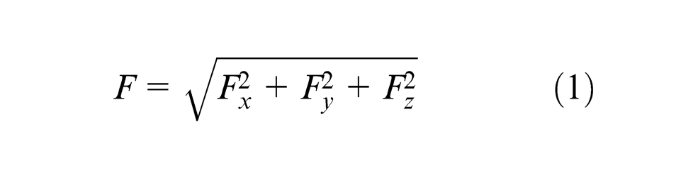
Cutting forces (unit: N).
where Fx, Fy, and Fz are the values of cutting forces in the directions of x, y, and z.
The pressure (P) of the contact area between PCD tool and chips is calculated with equation (2)

where F is the peak value of resultant force obtained from equation (1) and S is the maximum contact area between PCD insert and the chip, which is equal to the product of feed rate and axial cutting depth: fz×ap.
As shown in Table 6, there is a big variation in the pressure when cutting parameters are changed. The minimum value of P in the nine tests is 3419 N/mm2, while the maximum value is up to 7861.53 N/mm2. It can also be seen that the pressures of Test 1, Test 4, and Test 7 are very high, all of which are above 5000 N/mm2.
Analysis of surface quality
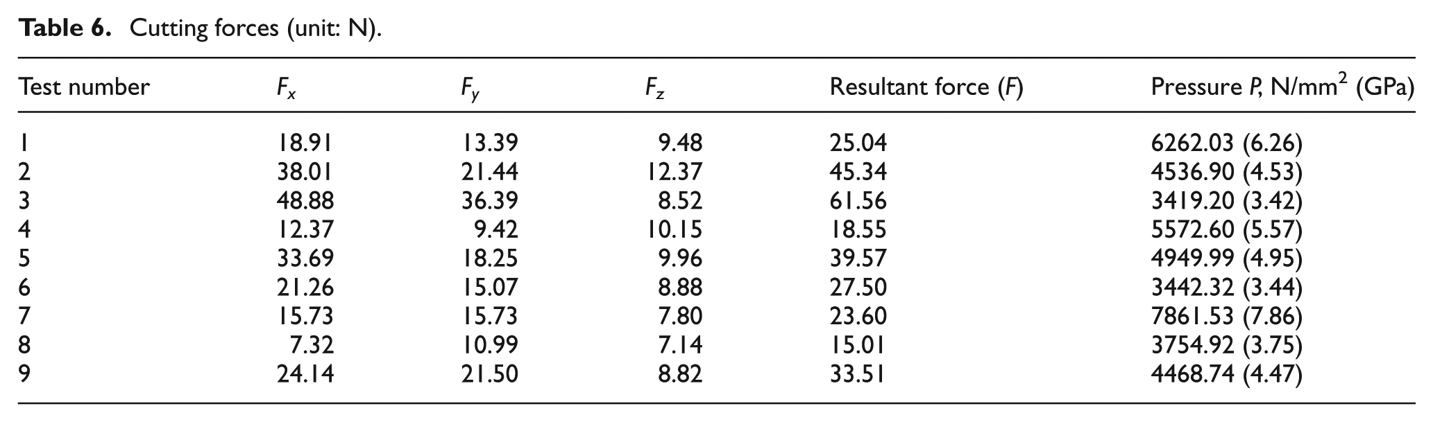
Table 7 shows the analysis of cutting force under different machining conditions. MaxErr is the errors between the average cutting force and the maximum force, MaxForce is the maximum value of cutting force, and MinForce is the minimum value of cutting force.
Analysis of cutting force.
MaxForce: the maximum value of cutting force; MinForce: the value of minimum cutting force; MaxErr: the errors between the average cutting force and the maximum force.
According to MaxErr, it can be seen that cutting speed Vc has small effect on the stability of cutting force. MaxErr increases significantly with the increase in ft and ap. The cutting force becomes more unstable when larger feed rate and axial cutting depth are used. However, MaxErr remains at a low level when feed rates are between 0.01 and 0.06 mm/rev.
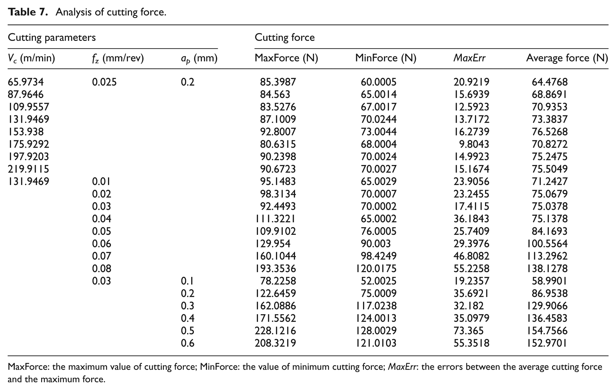
Figure 4 shows the profiles of finished surfaces that were machined with different cutting parameters. The length measured in each profile is 1.8 mm. The average distance (AD) between the peak and central axis (refer to Figure 4) was used to analyse the surface quality. Figure 4(a) and (b) is to compare the results of different cutting speeds; Figure 4(c) and (d) is to compare the results of different feed rates.
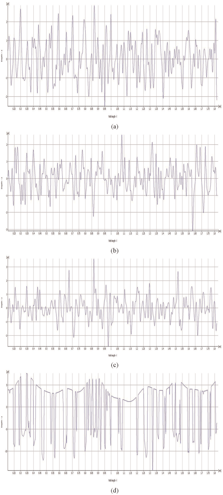
Profiles of titanium workpiece obtained with different machining parameters: (a) cutting speed of 65.97 m/min, (b) cutting speed of 175.92 m/min, (c) feed rate of 0.01 mm/rev, and (d) feed rate of 0.08 mm/rev.
Based on the profiles shown in Figure 4(a), the AD is found to be 1.85 µm when cutting speed is 65.97 m/min (Figure 4(a)) and 1.3 µm when cutting speed is 175.93 m/min (Figure 4(b)). It is clear that the surface finish of the workpiece machined with a cutting speed of 175.92 m/min is slightly better than that of 65.97 m/min. In Figure 4(c) and (d), a sharp contrast exists between the workpiece machined with feed rates of 0.01 and 0.08 mm/rev. The AD of 0.01 mm/rev is 1.5 µm, but the AD of 0.08 mm/rev is up to 5 µm. Overall, it can be concluded that the surface quality became poor when large feed was applied; higher cutting speed and lower feed rate can result in better surface quality. However, according to the results of Table 7, to use the feed rate in the range of 0.01–0.06 mm/rev, the cutting force will vary slightly, which indicates that the surface quality will not be affected significantly.
Cutting temperature and chemical components
High cutting temperature causes the PCD tool to experience performance problems. For example, different thermal expansion rates between the diamond and the catalysing material cause the PCD to crack or chip when the temperature of the PCD tool exceeds about 700 °C; 23 and the presence of the catalysing material causes the graphitization of diamond particles inside the PCD when the temperature reaches 700 °C. The graphitization process causes the PCD element to crack and decreases its useful lifespan. Therefore, it is important to ensure that the cutting temperature is below these values.
Similar to Pittalà and Monno, 24 the cutting temperatures in the milling processes were measured in our experiments by using a thermal imaging infrared camera (FLIR ThermaCAM). The thermal images taken in Test 1 and Test 17 are shown in Figure 5. The highlighted area in the image shows the average temperature of the cutting region.
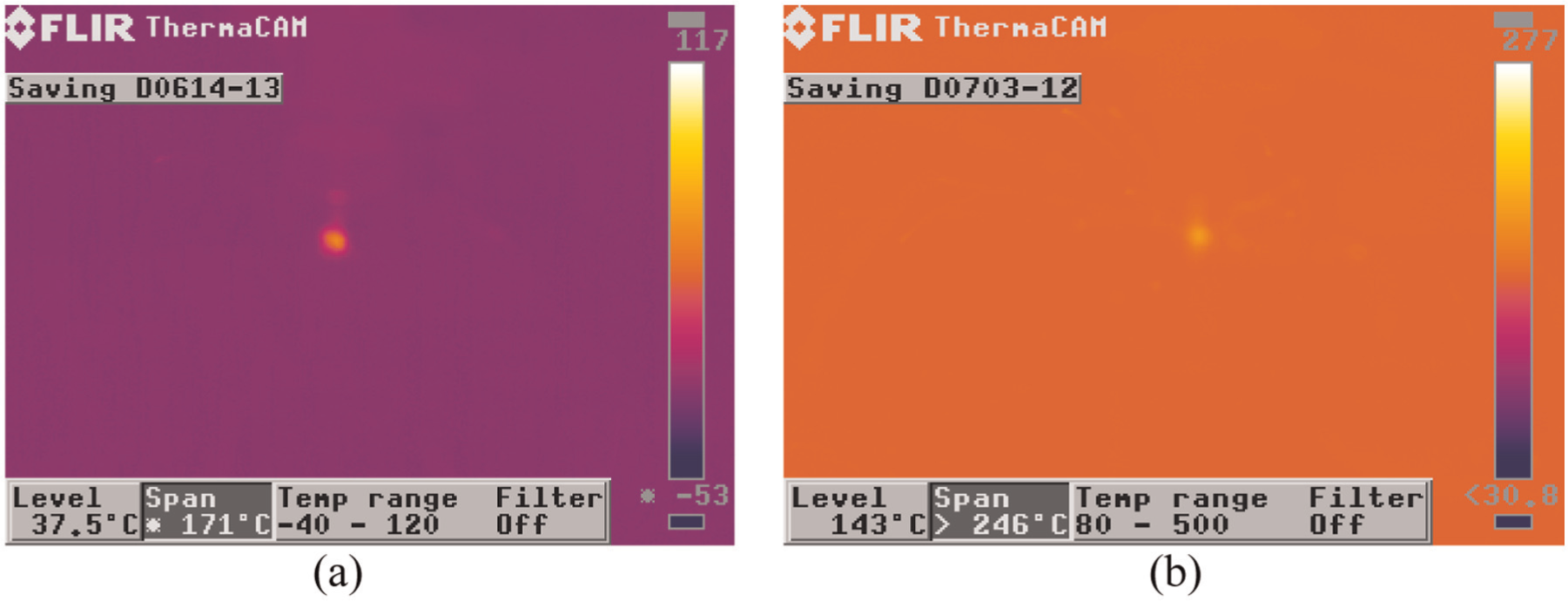
Cutting temperature measured with thermo infrared images: (a) infrared images in Test 1 and (b) infrared images in Test 17.
According to Figure 5, the temperature in Test 1 was less than 100 °C, while the average temperature in Test 17 was up to 170 °C. The temperature increased by nearly 70 °C in Test 17 due to the change in machining parameters. Since the dimension of the PCD insert is small and the coolant was splashing in the cutting region, the temperature measured with the infrared images is not accurate enough to reflect the exact temperature at the cutting edge of the PCD tool. The temperature obtained is lower than the real temperature of the cutting tool. It is hard to tell whether the highest temperature at the small cutting edge of the insert is above 700 °C or not just based on the temperature shown in the images.
It is known that the chemical reaction between Ti6Al4V and carbon will occur in the air at the evaluated temperature of up to 500 °C, and the results of the chemical reaction are new compounds of TiC, TiO, or Ti2O3. If no such components are found in the machining process, it can be concluded that the chemical reaction might not happen, which indicates that the temperature is less than 500 °C.
XRD is a method that can be used to determine the chemical components by analysing the spectrum of target specimen. Two PCD tools fabricated with the same type of PCD material and same geometric parameters but undergone different cutting tests with different cutting parameters were examined. Figure 6 shows the XRD results of samples which were taken from Test 1 and Test 17 with the detailed machining parameters shown in Table 5. The horizontal axis represents the scanning degree of specimen, and the vertical axis represents the value of intensity of the detected elements.
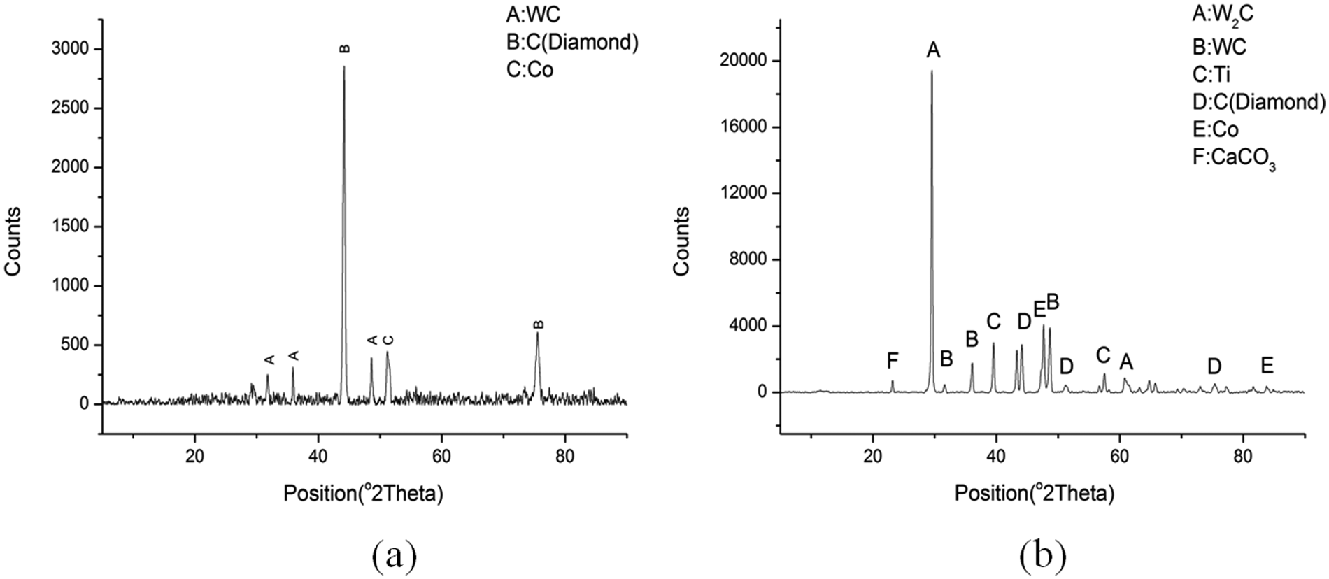
The X-ray diffraction analysis of PCD inserts: (a) XRD result of PCD insert in Test 1 and (b) XRD result of PCD insert in Test 17.
As illustrated in Figure 6(a), tungsten carbide, carbon (diamond), and cobalt were found in the first sample. However, titanium was found in sample 2 (Figure 6(b)), which is caused by the diffusion effects at high temperature; no chemical compounds of TiC, TiO, Ti2O3, or graphite were found. Therefore, it can be concluded that no massive chemical damage occurred on PCD cutter, and the cutting temperature at the cutting edge might be below 500 °C.
Effects of cutting speed, axial cutting depth, and feed rate
To analyse the individual influence of cutting speed, axial cutting depth, and feed rate, dynamic cutting forces were measured with sampling frequencies of 40 and 30 kHz. Figure 7 shows the cutting forces when cutting speeds were 65.97 and 219.91 m/min. It can be seen that cutting forces increase with the cutting speeds slightly. This result agrees to that found by Barry et al. 25 According to Schrock and Kwon, 15 cutting forces may decrease with the increase in cutting speed in high-speed machining due to the softening effects when high cutting speed and large feed and axial cutting depth were applied. However, the machining condition adopted in this experiment was different: the cutting speed was relatively slower, the cutting tool material enjoys much higher thermal conductivity, and the cutting temperature of most area was much less than 800 °C. As was found by Ezugwu and Wang, 26 no significant softening effect would occur if the cutting temperature was below 800 °C. Therefore, the increase in cutting speed may result in the increase in cutting forces rather than the decrease of it.
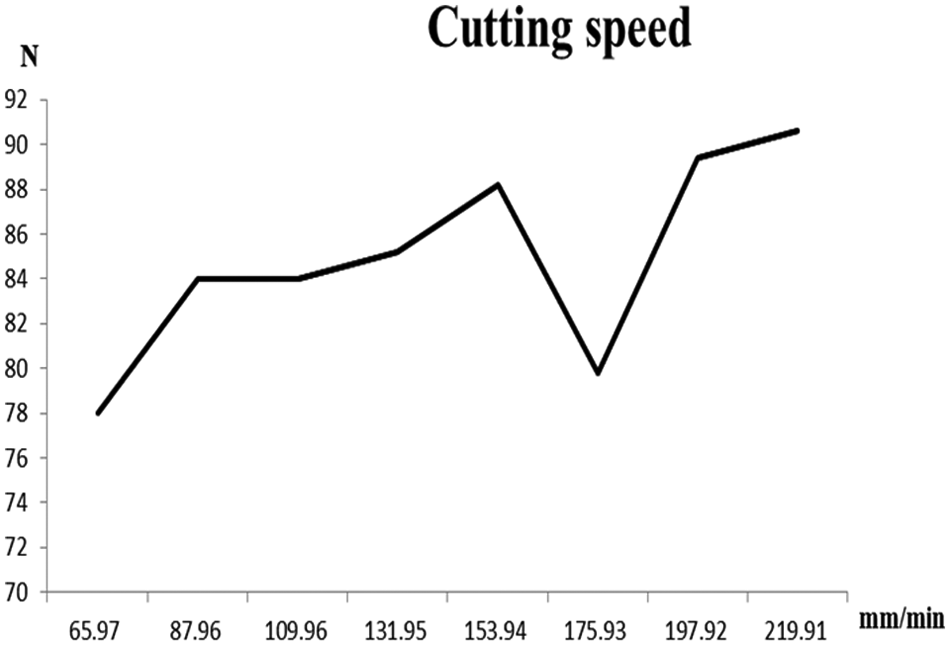
Dynamic cutting force.
Figure 8 illustrates the results of Tests 13–22. The cutting forces increase with axial cutting depth and feed rate. The cutting force in z-axis does not have significant change apparently. Since the gradient in Figure 8(a) is bigger than that in Figure 8(b), the effect of change in axial cutting depth is more significant than feed rate. The big cutting force is detriment to the surface quality.
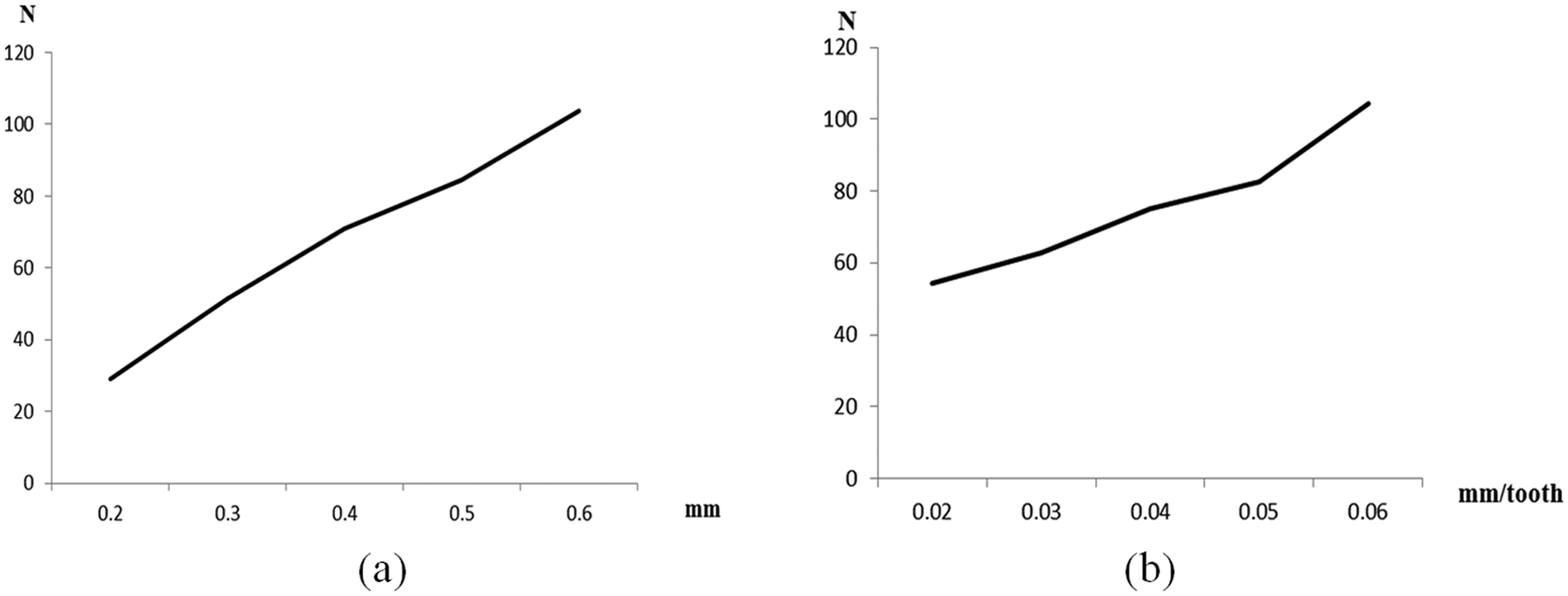
(a) The cutting forces versus axial cutting depths and (b) the cutting forces versus feed rates.
Analysis of initiation of cracks
The shaded area in Figure 9(a) indicates the contact area between PCD insert and Ti6Al4V workpiece. In each milling cycle, shearing occurred on the boundary of the contact region. As calculated in Table 6, the range of pressure on the PCD is from 3419.20 to 7861.53 N/mm2 (i.e. from 3.4 to 7.86 GPa). Among the first nine tests, the pressures in Test 1 and Test 7 are significantly bigger than the others. When the PCD inserts were periodically loaded under these pressures, brittle cracks could be initiated on the shear plane and progressively resulted in tool failure in the milling cycles.
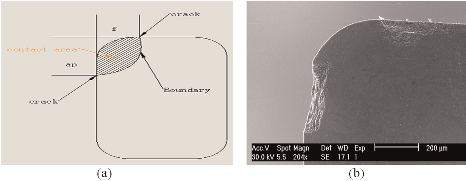
The illustration of PCD insert and the SEM of the worn PCD tool: (a) the sketch of contact zone between PCD insert and workpiece and (b) side view of damaged PCD insert.
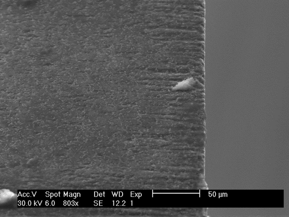
Stress concentration was one of the possible reasons which lead to cracking. Figure 10(a) shows a new PCD insert with a tiny notch at the cutting edge; Figure 10(b) shows that the chipping occurred at the same location of the insert after the tool was damaged in the machining process. This indicates that the existence of innate notches could possibly initiate cracks. Normally, the stress concentration always occurs on the blunt edge or the place with notches.
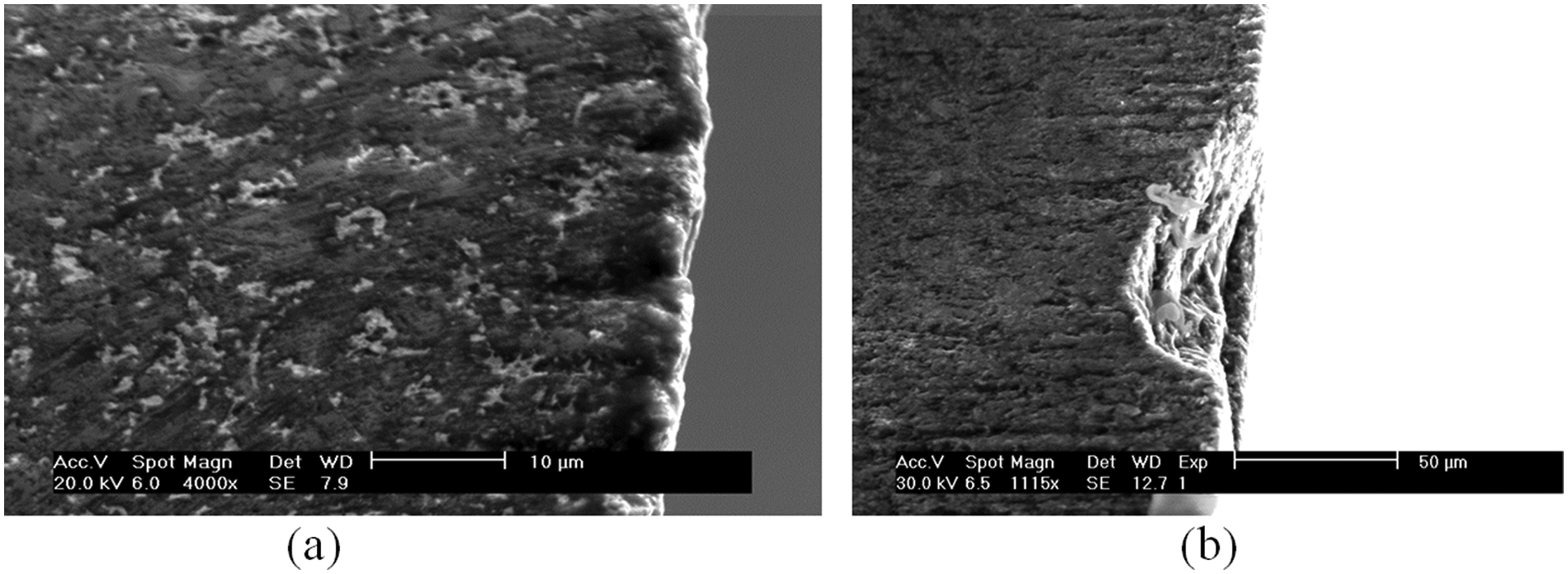
SEM photographs of cracking on the PCD insert: (a) the irregular cutting edge of new PCD insert and (b) the damaged spot on the same PCD insert.
In order to further analyse the failing process of PCD tools, two FEA models were developed by using the commercial software program Abaqus v6.11. In the FEA models, the same geometric parameters and material properties of the PCD inserts used in the cutting test were applied. Two simulations were conducted: the simulation of stress concentration on PCD tool edge with notches and the simulation of brittle cracking on PCD tool edge. In the first model, extended finite element method (XFEM) was used to simulate the cracking on the notched edge of the PCD tool. The maximum principal stress (MAXPS) was employed as the failure criterion. The maximum compressive stress was 2.1 GPa, 27 and the failure displacement of specimen was 0.2 mm. 28 The pressure in contact area was set to be 5.5 GPa as shown in Table 6.
The second FEM model was developed to simulate the catastrophic damage on the nose of PCD insert at the last period of milling test. The material model was brittle cracking in which Rankine criterion was used. The direct stress after cracking was the same as the compressive limit in the first model. The failure displacement was 0.2 mm.
The result of the first simulation was shown in Figure 11(a). It can be seen that stress concentration occurred at the notch of PCD insert after the pressure of 5.5 GPa was loaded on the contact area, and the initiated cracks appear on the notch. This indicates that the cutting edge of PCD which has notch is prone to stress concentration during the milling process and will lead to tool failure. Therefore, a well-grinded PCD tool with sharp edges is needed to avoid the crack initiation on the tool cutting edge. The catastrophic damage shown in Figure 11(b) illustrates that the PCD collapses along the shearing boundary of contact area. This result matches the fractograph of the damaged tool.
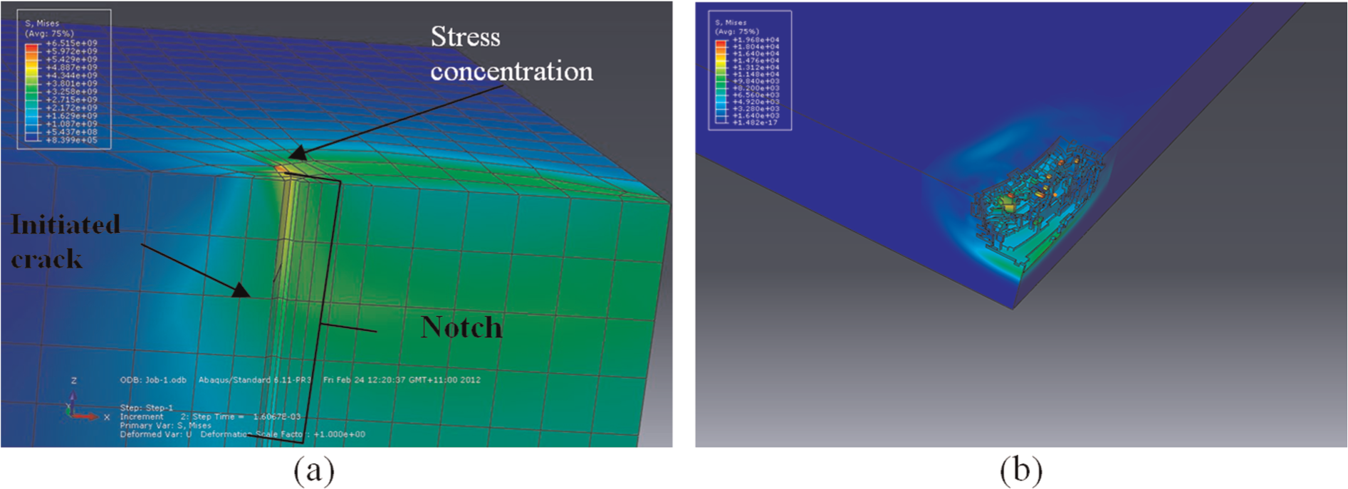
The simulation of crack initiation with the load of 7.9 GPa: (a) the simulation of cracking initiation and (b) the simulation of used PCD material collapse.
Fractograph and fracture mechanism of PCD inserts
Due to the special inhomogeneous structure of PCD, the wear and failure mechanism of PCD tool are more complicated than conventional cutting tools made of homogeneous materials such as carbide and carbon tungsten. The wear and failure could be caused in the forms of adhesion, abrasion, brittle chipping, fatigue, graphitization, and chemical reactions, 29 or the combination of multiple factors. In our experiments, brittle and fatigue damages (Figure 12) were found to be the main forms of PCD tool wear. Details of PCD fractograph and causes of tool wear are discussed as follows.
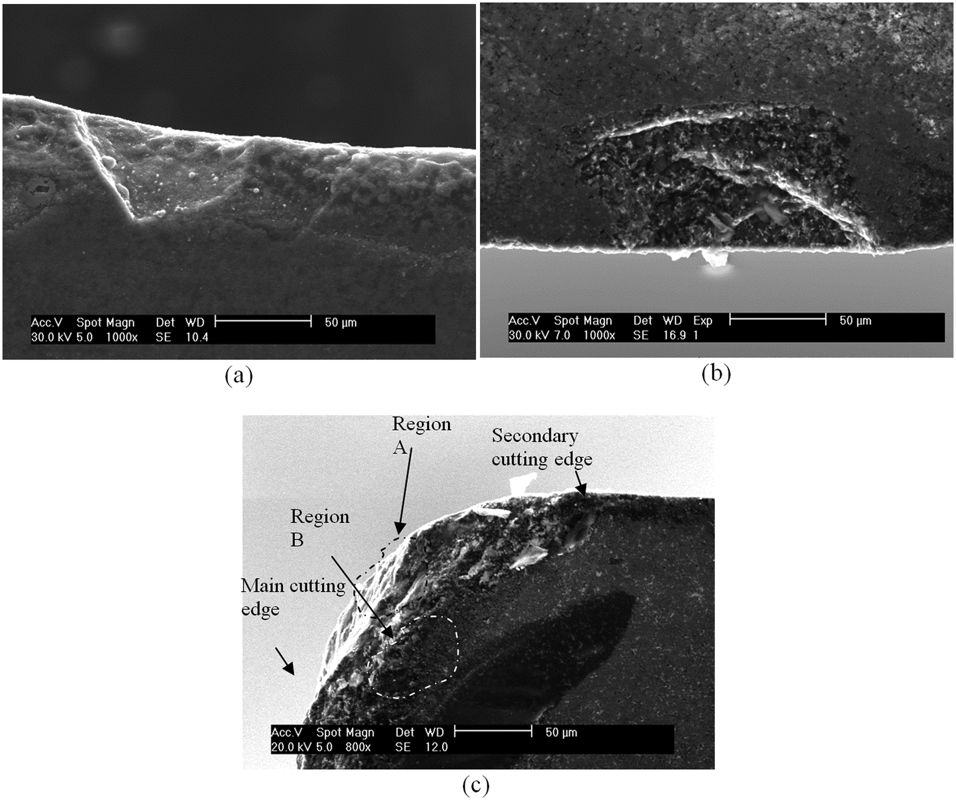
SEM image of damaged PCD samples: (a) cleavage-like fractograph on the secondary cutting edge, (b) the cohesive rupture and delamination on the secondary cutting edge, and (c) the directional damage at different regions on the PCD insert.
Figure 12(a) shows the cleavage-like fractograph of the PCD tool. It was found on the tool used in Test 7. Figure 12(b) shows the fractograph of the delamination and cohesive rupture on the PCD tool used in three tests (Tests 1–3). Figure 12(c) shows the cracks propagated in two directions; the tool was examined after eight tests (Tests 10–17) were completed. The detailed machining parameters are shown in Table 5.
As shown in Table 6, the average pressure on the PCD tool in Test 7 is around 7.86 GPa. It can be seen in Figure 12(a) that no significant plastic deformation occurred and no dimple ruptures can be found. Flank wear at the edge is visible. It is reasonable to assume that the chipping section of PCD insert was rubbed in the milling process. The friction effect was the main factor for this kind of failure. The rubbing process removed little material from the original fractograph and ‘polished’ it.
Delamination was found on both Figure 12(b) and (c). Being the sintering material, the inside physical structure of PCD, the binding between cobalt and diamond particles, and the binding between diamond and diamond particles determine the mechanical properties. The chance of the break of these bindings or the dislodgement of diamond particles from the structure is unpredictable. The delamination in the fractograph is caused by the inhomogeneous property of PCD. The innate voids of the material distribution inside PCD can contribute to such kind of failure.
In Figure 12(c), the big damage area on the insert can be roughly divided into two different regions: Region A and Region B. In Region A, the crack or the fracturing path propagated along the direction which is vertical to the cutting surface. In Region B, the rubbing occurred at the main cutting edge. Region A is the result of the overloading on brittle material. The brittle cracking happened when the pressure became higher than the compressive limit. The cracks propagated in the direction of pressure and finally led to the collapse of the PCD. As for Region B, this area bore less stresses in the process. When the normal pressure was above the compressive limit of PCD, the shearing occurred at the contact boundary of the secondary cutting edge. But the area of Region B might bear the low normal pressure which was lower than the compressive limit of PCD. Therefore, it is reasonable to believe that the friction effect dominates this area.
Analysis of tool life
Unlike the turning process, the cutting edge of a milling tool is under continuous cyclical impact of the periodical cutting force. A few loading cycles would not result in obvious cracks on the PCD surface, 27 what were generated were 100–1000 indentations. With the increase in the number of cycles, fatigue mode of failure may cause damage to the PCD. Similar phenomenon had been observed by Lin et al.: 27 the PCD was broken after 5000 loading cycles with a load of 30 kN. The compressive strength of notched PCD compact varied from 1.9 to 4.7 GPa; the PCD tool was broken after 28,671 cycles when quasi-static loads were applied.
In our cutting experiments, when the normal pressure was up to 4.9 GPa, no obvious crack was found on the edge or the normal surface of the PCD insert after 4265 cycles (Figure 13). When the number of cycles reached 27,750, micro-chipping appeared (Figure 10(b)). Also, inconsistent tool life was found among the same type of PCD tools: under the same cutting conditions, different tools made with the same type of PCD showed different tool life or cutting performance. Figure 14 illustrates the photographs of the tools which were taken after 24,000 cycles. It can be seen that one tool (Figure 14(a)) maintains sharp cutting edge, but damages occurred in the other tool (Figure 14(b)). The cause that leads to such ununiformed performance is the random distribution of initial defects in the PCD material. The numbers of defects and some large voids in PCD can reduce Young’s modulus and density distribution inside the PCD. 30
SEM image of the PCD tool after 4265 loading cycles.
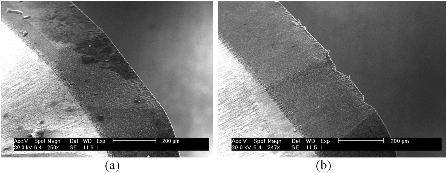
SEM images of two PCD samples after the same loading cycles: (a) the undamaged PCD sample which was examined after 24,000 milling cycles and (b) the damaged PCD sample which was examined after 24,000 milling cycle.
Conclusion
The performance of PCD tools in end milling of titanium alloys (Ti6Al4V) is analysed in this article. It was found that cutting force was more sensitive to the change in feed rate than the changes in cutting speed and axial cutting depth. Cutting force increased with the increase in feed rate. Best surface quality was achieved when the cutting speed was 175.9 m/min. The optimized feed rate ranges from 0.01 to 0.06 mm/rev.
To study the wear mechanism of PCD tools, chemical components on the PCD surface were examined by using XRD method. Experiment results show that no massive chemical reaction had happened in the milling process with the selected cutting parameters, and the cutting temperature was below 500 °C.
No damage was caused on the PCD inserts after 4265 loading cycles with the normal pressure of up to 4.9 GPa. A small damage of 0.05 mm was found after 24,000 cycles with the same normal pressure.
Directional damages by the shearing and friction were found in the experiments. The cleavage-like fractograph was mainly caused by the rubbing effect in the process and it appeared rarely in the experiment. The inhomogeneous material structure of PCD was the major factor which caused the delamination.
Footnotes
Declaration of conflicting interests
The authors declare that there is no conflict of interest.
Funding
This research received no specific grant from any funding agency in the public, commercial, or not-for-profit sectors.