
Abstract
The research presented in this article aims at developing an innovative integrated modelling methodology to quantify the energy consumption and equivalent carbon footprint in the grinding process. This article categorizes the energy consumption in four compositional parts and identifies the associated key factors affecting the energy consumption and equivalent carbon dioxide emission during the grinding process. Considering energy consumption (E), resource utilization (R), waste generation (W) and their collective effect on equivalent carbon dioxide (C) emission (ERWC), quantitative analysis modelling of the entire grinding process is developed against the roughing, finishing and spark-out stages of the process. The modelling and simulation analysis are carried out with the MATLAB environment, supported by the evaluation and validation through well-designed grinding trials.
Introduction
Low-carbon manufacturing or energy-/resource-efficient manufacturing is becoming increasingly important for modern manufacturing industry, while quantitative analysis of energy consumption and carbon dioxide emission in manufacturing processes is essential for scientific understanding and industrial implementation of energy-/resource-efficient manufacturing. Grinding is a widely used precision machining method, but the process consumes more energy and lubricant and generates more waste than other processes such as turning and milling. The thermal prone grinding zone usually requires a large amount of flooded fluid, but its reuse and disposal impose severe environmental impact. Furthermore, regular dressing of grinding wheels is an inevitable consumption process of energy and resources. Therefore, the investigation on energy consumption and carbon footprint in the grinding process is of high industrial and scientific significance, although it is carried out as an exemplar and the methodology is applicable to other machining processes.
Based on the machining processing sequence, Dahmus and Gutowski 1 categorize the power consumption of machine tools into three different modes, that is, idle mode, run-time mode and production mode. Numerous studies on energy have been carried out based on these three modes, for instance, Li and Kara 2 developed a reliable method to predict the total energy consumption of a selected machine tool performing a turning operation. Dietmair and Verl 3 established the energy consumption behaviour of machines and plants based on a statistical discrete event formulation to exploit the minimization of energy consumption at any given machine or production system. Tridech and Cheng 4 concluded that decreasing the idle time and downtime help minimize energy consumption. Behrendt et al. 5 developed an energy consumption monitoring procedure for machine tools, which is useful for companies to establish some standard practices. He et al. 6 analysed the correlation between numerical control (NC) codes and energy-consuming components of machine tools and proposed a practical method for estimating the energy consumption of NC machining. Ball et al. 7 developed a tool to support the development of a zero carbon manufacturing system in a very broad scope. However, an essential challenge is a lack of a generic quantitative analysis method on energy consumption in the machining process, which can be comprehensively applicable to the machining operations and the associated machine tools.
This article presents an innovative integrated methodology for quantitative analysis of energy consumption in the grinding process covering four parts – material removal energy consumption, basic energy consumption, frequency-converted energy consumption and response energy consumption – and consequently the equivalent carbon footprint of the process. The research has taken the centreless grinding process, as shown in Figure 1, as the application exemplar to evaluate and validate the methodology through well-designed grinding trials. The modelling and simulation of the energy consumption focus on a generic ERWC approach to quantitatively analyse the collective energy consumption (E), resource utilization (R) and waste generation (W) and the resultantly equivalent carbon dioxide emission (C) in the grinding process.
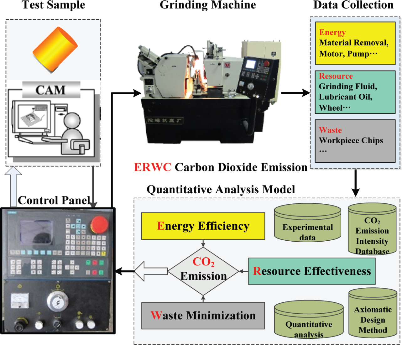
Quantitative analysis of energy consumption and equivalent CO2 emission in the grinding process.
Energy consumption in the grinding process
Energy consumption in material removal
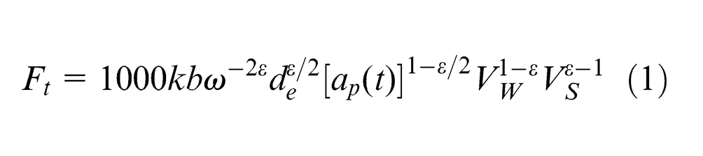
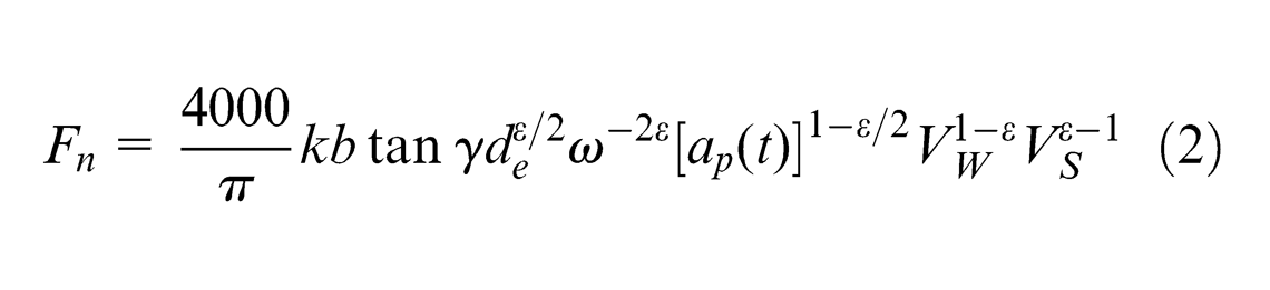
According to Wang et al., 8 Wang and Ding, 9 Zhu 10 and Zhou, 11 tangential and normal grinding forces are
In the grinding process, the machine stiffness is a key factor to influence

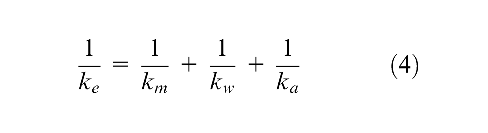
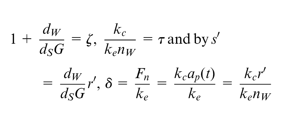
where the grinding system equivalent stiffness coefficient is
Assume that
Suppose
then equation (5) can be expressed as

here
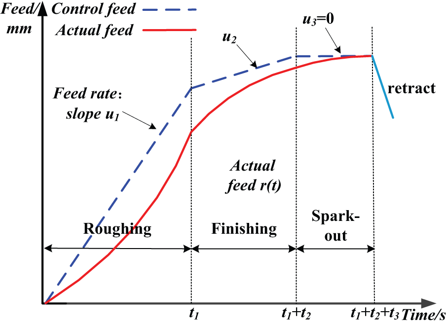
A typical grinding process cycle with roughing, finishing and spark-out stages.
From equation (6), we can find out that the grinding depth per revolution depending on grinding time
Roughing stage:

Finishing stage:
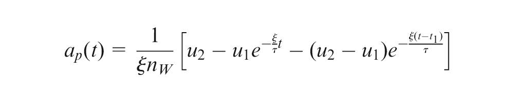
Spark-out stage:
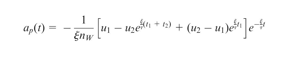
Substituting
where the signs correspond to the climb-cut and down-cut, respectively.
Basic energy consumption
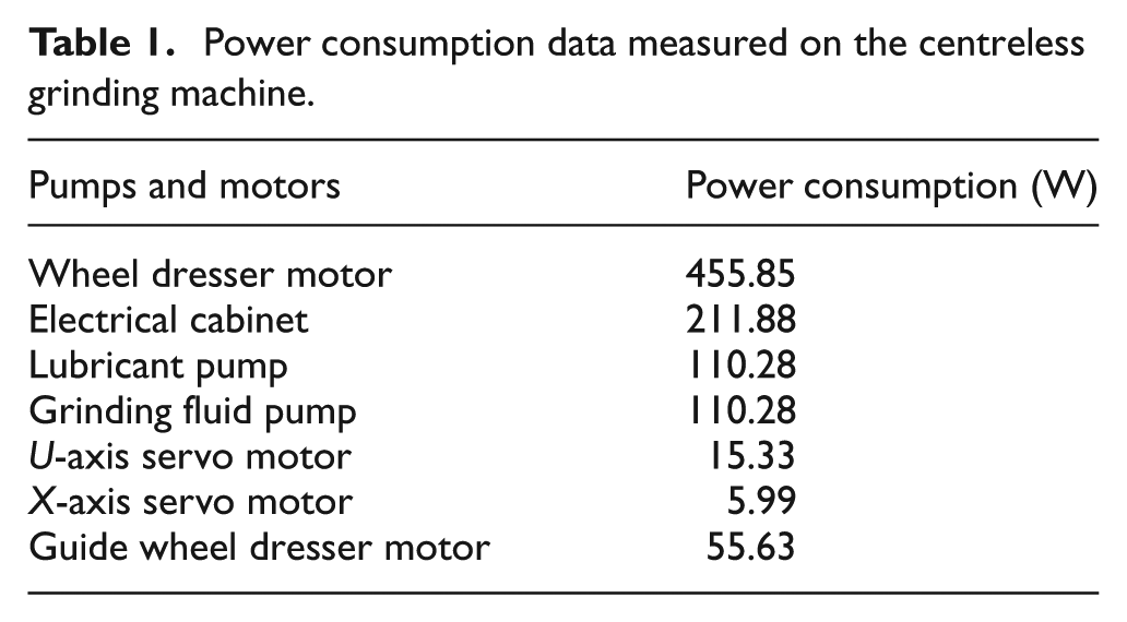
Some basic energy consumption is needed to maintain the normal operation of the grinding machine, which includes the energy consumption of coolant pump, lubricant pump and electric cabinet. This part of power consumption can be measured by using a Fluke 1735 Power Logger. Table 1 shows the measurement results of the centreless grinding machine.
Power consumption data measured on the centreless grinding machine.
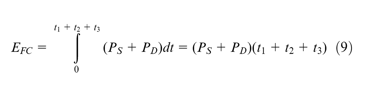
Frequency-converted energy consumption
Besides basic energy, energy consumption of grinding wheel drive motor and guide wheel drive motor in no-load are two other indispensable elements to make the grinding machine function well. These two adjustable frequency motors can change the rotational speed by control knobs. According to Zhang,
12
the power of these two motors can be expressed as a quadratic function of rotational speed. Then, the frequency-converted power of the grinding wheel motor

Response energy consumption
Because of the workpiece being grinded, the grinding machine needs more energy besides the material removal, basic and frequency-converted energy. We call it as response energy. It includes additional guide wheel drive motor power load caused by bearing friction and tangential friction force between the workpiece and the guide wheel. Because of the bearing’s small size and fine lubrication conditions, we emphasize the latter one.
In the grinding process, the workpiece has relevant immobility under the action of seven forces: workpiece’s own gravity and three pairs of pressure and friction from the grinding wheel, guide wheel and supporting plate to workpiece. They are marked in Figure 3.
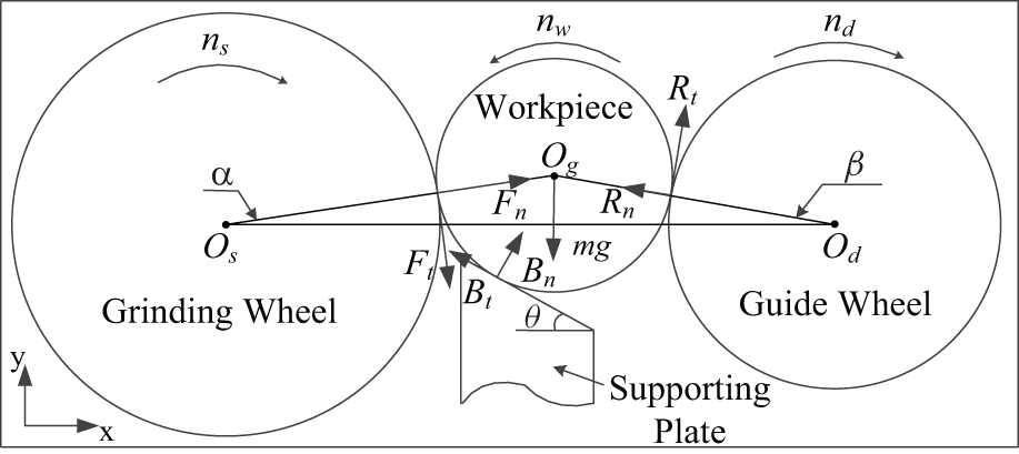
Workpiece force diagram.
Then, the force balance equations are as follows
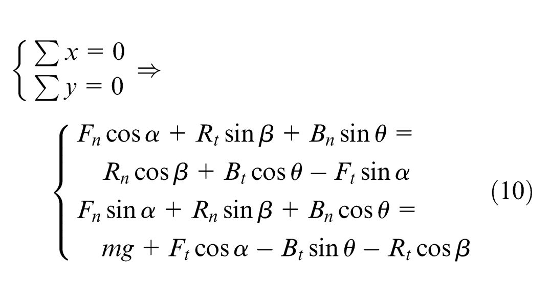
The tangential grinding force
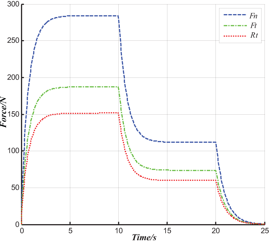
Curves of the three force components in the grinding process.
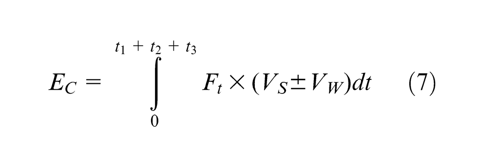
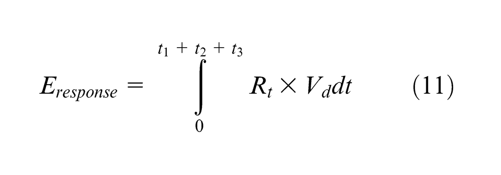
So, the response energy consumption is calculated as
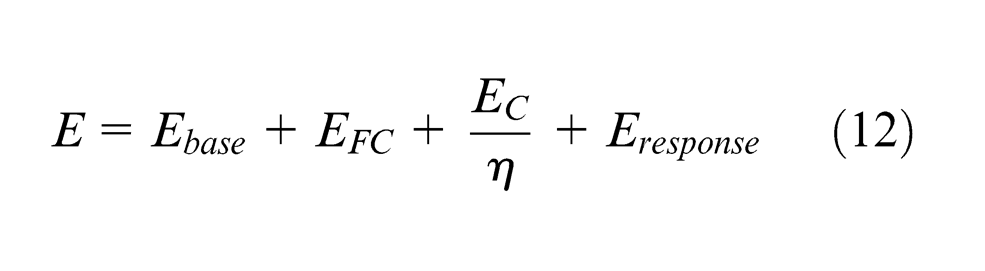
Suppose grinding efficiency coefficient is η, the energy consumption of grinding process E is as follows
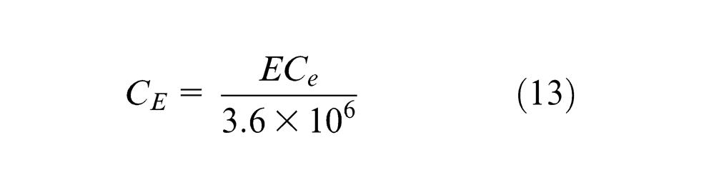
Carbon dioxide emission and energy consumption of grinding machine are calculated as
Equivalent carbon dioxide emission resulted from the process resource usage and waste disposal
Equivalent carbon dioxide emission from the grinding wheel usage
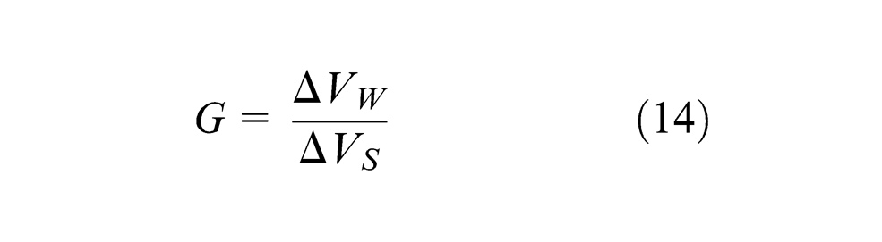
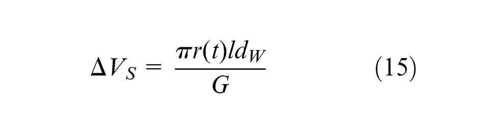
The grinding ratio G (G-ratio) is defined as the ratio of the volume of accumulated metal removal to the accumulated lost volume of the grinding wheel, and it is expressed as
Then, the accumulated lost volume of wheel is expressed as
The accumulated lost volume of wheel dressing is expressed as
The equivalent carbon dioxide emission of wheel dressing is expressed as
The equivalent carbon dioxide emission from the grinding wheel usage is calculated as
Equivalent carbon dioxide emission from the grinding fluid usage
Grinding fluid is an indispensable resource in the grinding process. Grinding fluid can not only cool down and lubricate the grinding zone but also swash wear debris. As we all know, grinding is a precision machining method. To ensure grinding precision, grinding fluid should be entirely replaced regularly. The equivalent carbon dioxide emission from the grinding fluid usage is calculated as
Equivalent carbon dioxide emission from the lubricant oil usage
Many parts of the grinding machine system should be lubricated regularly. We make an equivalent to spindle lubrication. The equivalent carbon dioxide emission from lubrication oil usage is calculated as
Equivalent carbon dioxide emission from the grinding chips disposal
The accumulated metal removal volume
Based on the study by Narita et al., 13 carbon dioxide emission intensities mentioned above are listed in Table 2.
Equivalent carbon dioxide emission intensities.
ERWC carbon dioxide emission quantitative analysis model and a case study
From the above analysis, the time-varying equivalent carbon dioxide emission quantitative analysis model in the grinding process can be represented as follows
We have some 20-mm-diameter cylindrical workpieces, which are made of 45 gauge steel. MK1080 centreless grinding machine is chosen and the grinding depth is 0.2 mm. Table 3 shows three NC programs used for comparison, and the parameters are empirical data from the grinding machine operator.
Grinding NC program parameters.
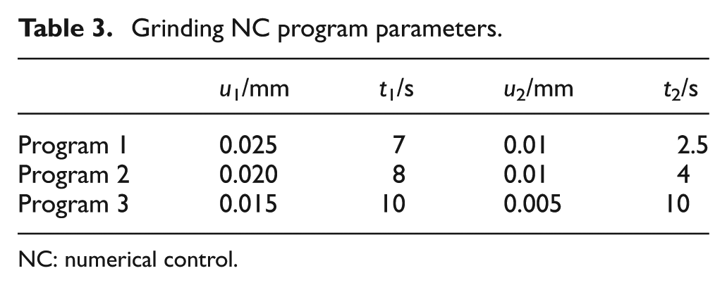
NC: numerical control.
The time-varying equivalent carbon emission curves of the three NC programs were shown in Figure 5. For program 1, due to its greater feed rate, it let out more carbon dioxide at the beginning. However, its final emission was the least one because of consuming least time.
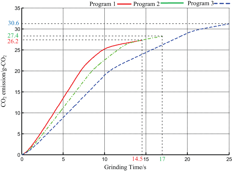
Equivalent carbon dioxide emission curves during grinding processes.
Comparing Figures 2 and 5, we can also find out that equivalent carbon emission curves had strong relevance to feed rate. In general, bigger feed rate meant faster carbon emission rate. Compared with other machining processes, the result is consistent with the conclusion that the energy requirement decreases as the material removal rate increases, as described by Gutowski et al. 14 and Rajemi et al. 15
Figure 6(a) shows the equivalent CO2 emission of the four kinds of grinding energy consumptions mentioned before. We can find that the material removal energy accounts for the largest proportion, while response energy the smallest one. The percentage of material removal energy consumption is 56%. The result is not in the range as reported in literatures by Kardonowy, 16 Dahmus and Gutowski 1 and Rajemi et al., 17 who indicated that power distribution for machining lies in the range of 0%–48.1% depending on machine loads. On the other hand, it may indicate that the grinding process consumes more specific energy than turning or milling. Figure 6(b) shows that energy consumption and grinding wheel usage are two main factors resulting in carbon dioxide emission in the grinding process under existing carbon dioxide emission intensities. The result that 50% of carbon dioxide emission is generated by energy, indicates that not only energy consumption, but also resource and waste should be taken into consideration to access carbon dioxide emission in manufacturing.
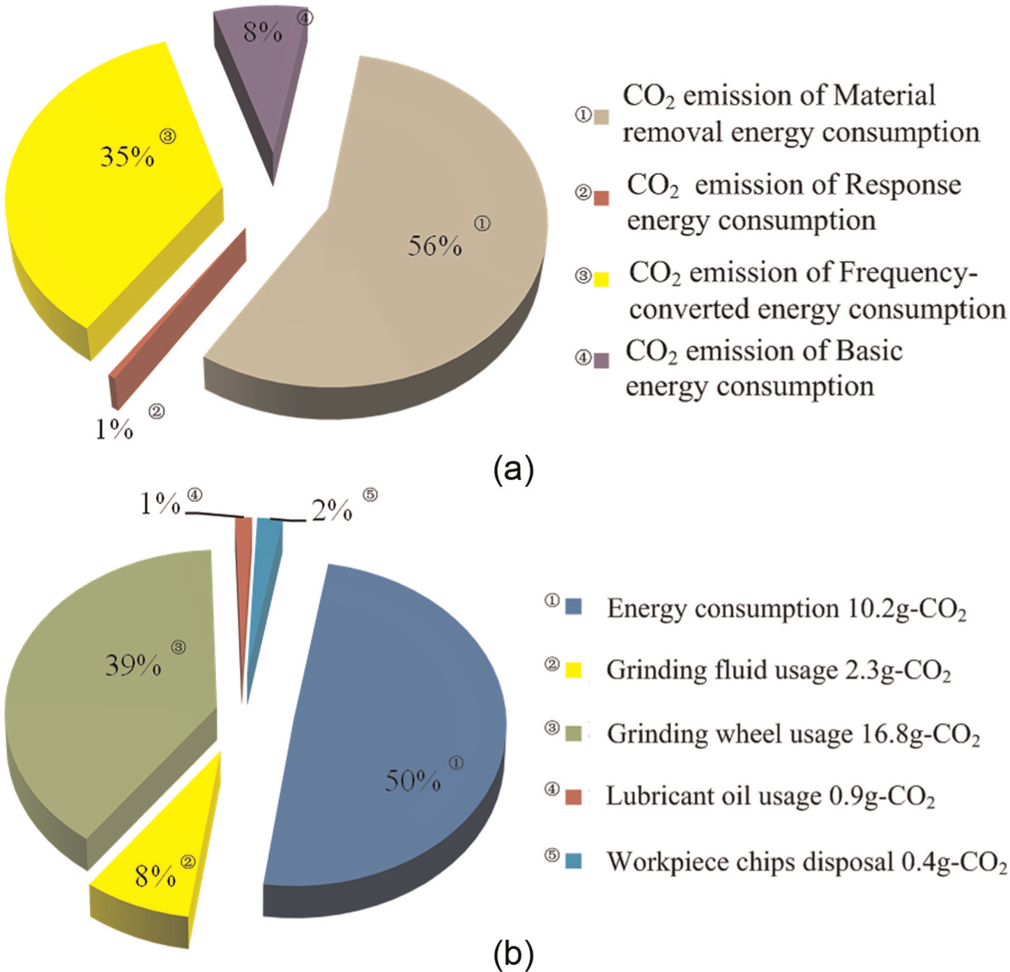
Quantitative analysis results: (a) proportion of energy influencing CO2 emissions and (b) proportion of factors influencing equivalent CO2 emissions.
Conclusion
This article presents an ERWC-based modelling approach to quantifying the energy consumption in the centreless grinding process and the associated equivalent carbon dioxide emission. The modelling is evaluated and validated by well-designed grinding trails. Currently, the ERWC models are further implemented in the computer numerical control (CNC) system to achieve the multi-dimensional process optimization by addressing the quality, productivity, costs and energy consumption simultaneously.
Footnotes
Appendix 1
Acknowledgements
The authors would like to thank Xianfeng Machine Tool Company for the provision of the centreless grinding machine and the grinding process as needed.
Declaration of conflicting interests
The authors declare that there is no conflict of interest.
Funding
This research was supported by ‘the Fundamental Research Funds for the Central Universities’ (grant no. HIT.NSRIF.2014057).