
Abstract
Variation modeling of sheet metal assemblies is quite critical when specifying and verifying the geometric and dimensional requirements of parts. However, sheet metal parts’ compliant behavior makes the variation modeling approach more complex when coupling both rigid variation in the in-plane direction and compliant variation in the out-of-plane direction. In order to completely model the overall three-dimensional variation of sheet metal assembly, a unified variation modeling approach considering both rigid and compliant variations is proposed in this article. Four types of coordinate systems are defined. In the in-plane direction, homogeneous transformation matrix is used to describe the position and orientation relationships between assembly elements, and differential motion vector is used to represent rigid variation. In the out-of-plane direction, a vector composed of the deviations of selected key characteristic points is used to represent compliant variation, and the method of influence coefficients is adopted to analyze compliant variation. The overall three-dimensional variation of sheet metal assembly is the superposition of both in-plane rigid variation and out-of-plane compliant variation. Three types of variation sources that are fixture locators’ deviations, datum features’ deviations and joint features’ deviations are considered here. A case study is presented to illustrate the proposed approach.
Introduction
Sheet metal assembly is a widely used manufacturing process in many industries such as aerospace, automobile, and electronics. Dimensional quality assessment of sheet metal assembly products, which are likely to be nonrigid or compliant, is very vital for the functionality and performance of final products. 1,2 However, due to imperfections in the assembly process such as fixture locators’ deviations from the nominal positions, part features’ deviations from the nominal geometry and part deformation caused by assembly operation, assembly variations may be introduced and cause the dimensional quality problem of product. Therefore, analyzing and reducing dimensional variation is of great importance for improving the product quality. 3
Methods for assembly variation analysis have been the subject of considerable amount of research and commercial applications. Jin and Shi 4 developed a state space model for dimensional variation analysis of sheet metal assembly. Similarly, Mantripragada and Whitney 5 proposed a state transition model to propagate and control variation in mechanical assemblies. Concepts and methods in control theory have been applied in variation analysis. Ding et al. 6 developed a two-dimensional (2D) state space model for variation analysis of multistage sheet metal assembly process. By introducing the sensitivity analysis in control theory, they defined a group of hierarchical sensitivity indices in the state space model for selecting a better design.
The approaches mentioned above are mainly focused on 2D rigid variation analysis. For more generality and applicability, three-dimensional (3D) rigid variation models have been developed. Huang et al. 7,8 built a 3D single-station assembly model and a 3D multistation assembly model based on stream-of-variation analysis (SOVA). The developed models take both product and process information into account and consider the variation propagation for 3D rigid part assembly. However, in Huang et al., 7,8 the state vectors defined as a stack-up of vectorial deviations of parts’ reference points are different between assembly stations, which makes it difficult to derive system matrices at different assembly station with a generic method. Furthermore, variations of part features are not considered in their model. Liu et al. 9 improved the 3D assembly variation model with a more generic state space modeling method based on differential motion vector (DMV). Various variation sources including fixture locators’ deviations, datum features’ deviations and operation deviations are considered in their variation model.
All the research works mentioned above are based on rigidity assumption, considering only rigid variations, and are limited to the analysis of assembly variation of deformable sheet metal parts. For instance, in Liu et al., 9 operation deviations are assumed to be given as model inputs and represented as DMV of part with respect to a given fixture. However, operation deviations are quite dependent on particular assembly operation situation and mechanics characteristics of parts. Moreover, operation deviations cannot be just represented as DMV of part with respect to fixture due to the deformation of sheet metal parts.
Ever since Takezawa 10 pointed out that the traditional addition theorem of variation was no longer valid for deformable sheet metal assembly, compliant variation analysis became an emerging and challenging field and has been researched intensively. Liu and Hu 11 developed a mechanistic variation model by applying linear mechanics and statistics. They constructed a sensitivity matrix for compliant part with complex shape based on the method of influence coefficients (MIC) to establish a linear relationship between the input part variation and output assembly variation. Camelio et al. 12 extended this methodology to evaluate the dimensional variation propagation in a multistation assembly system with compliant parts. To improve the computational efficiency of compliant variation analysis, Camelio et al. 13 proposed a new method for predicting assembly variation of compliant parts combining the use of principle component analysis and finite element analysis (FEA). Liao and Wang 14 studied the influence of the variation of surface micro-geometry of compliant parts on the assembly variation by combining fractal geometry and FEA. Sellem and Rivière 15 developed the influence matrix method (similar to the sensitivity matrix), which represents how the assembly deforms when a unit displacement is applied in a specific point. The above FEA approaches have been integrated into some FE-based variability simulation tools such as Siemens PLM VisVSA and CATIA V5 Tolerance Analysis of Deformable Assemblies (TAA) workbench. Cai et al. 16 presented digital panel assembly (DPA) methodologies including deterministic analysis and variation analysis for sheet metal assembly. Linear models without contact and nonlinear model with contact are established and Elastic Assembly Variation Simulation (EVAS) software was developed based on the proposed methodologies. In order to improve the simulation accuracy, Dahlstrom and Lindkvist 17 implemented a contact algorithm into MIC to prevent penetration between parts. Yu et al. 18 studied the influence of part material variation on assembly variation. Cheng et al. 19 presented an analysis method for variation propagation of aeronautical thin-walled structures (ATWS) with automated riveting by dividing the whole assembly process into two stages and eight states. Ceglarek and Prakash 20 proposed an enhanced piecewise least squares (EPLS) methodology to diagnose fixture fault failure in an ill-conditioned multistage assembly system with compliant parts. Franciosa et al. 21 presented an finite element method (FEM)-based computer tool for statistically analyzing variations occurring in assembly processes of flexible parts. Based on the compliant variation analysis methodologies, assembly processes including fixture layout, 22 –24 joint positions, 25,26 and assembly sequences 27,28 are optimized.
However, all the models and approaches for compliant variation analysis are only focused on the compliant variation of sheet metal assembly in the out-of-plane direction. In fact, sheet metal parts are rigid in the in-plane direction, and product and process variation sources will cause the rigid variation of sheet metal assembly in the in-plane direction, which cannot be neglected as well.
Therefore, a unified variation model considering both in-plane rigid variation and out-of-plane compliant variation is proposed in this article. Through the developed model, linear relationships between the overall assembly variation and variation sources are established. Fixture locators’ deviations, datum features’ deviations, and joint features’ deviations are considered, and the coefficients of the model are the functions of product/process design parameters.
The remainder of this article is organized as follows: section “Mathematical representation of assembly geometry” presents the mathematical representation of sheet metal assembly geometry. In section “Unified variation modeling of sheet metal assembly,” the explicit unified variation model of sheet metal assembly is developed with both in-plane rigid variation and out-of-plane compliant variation. In section “Case study,” an illustrative case study is given. Section “Conclusion and future work” draws the conclusions.
Mathematical representation of assembly geometry
Sheet metal assemblies are typical type-2 assemblies. 5 The final variations of sheet metal assemblies are crucially dependent on the part manufacturing quality, locating scheme, and assembly operation. Besides, due to their compliant characteristics, sheet metal assemblies will deform in the most flexible direction. Therefore, mathematical representations of all types of deviations in the assembly process are necessary for variation modeling of sheet metal assembly.
Coordinate systems
The assembly process of sheet metal assembly involves locating parts to each other by fixtures and joining parts together by joint features. In order to analyze the assembly variation, four types of coordinate systems (CSs) are defined to locate parts, features, and fixtures and express geometrical deviations between them.
Global coordinate system (GCS) is a CS in which all elements in the assembly are located and oriented. In this article, the GCS (denoted as OGXGYGZG in Figure 1(a)) is assumed to be error free and unchanged during the entire assembly process, and the Z-axis direction of GCS is set as the out-of-plane direction of sheet metal assembly.
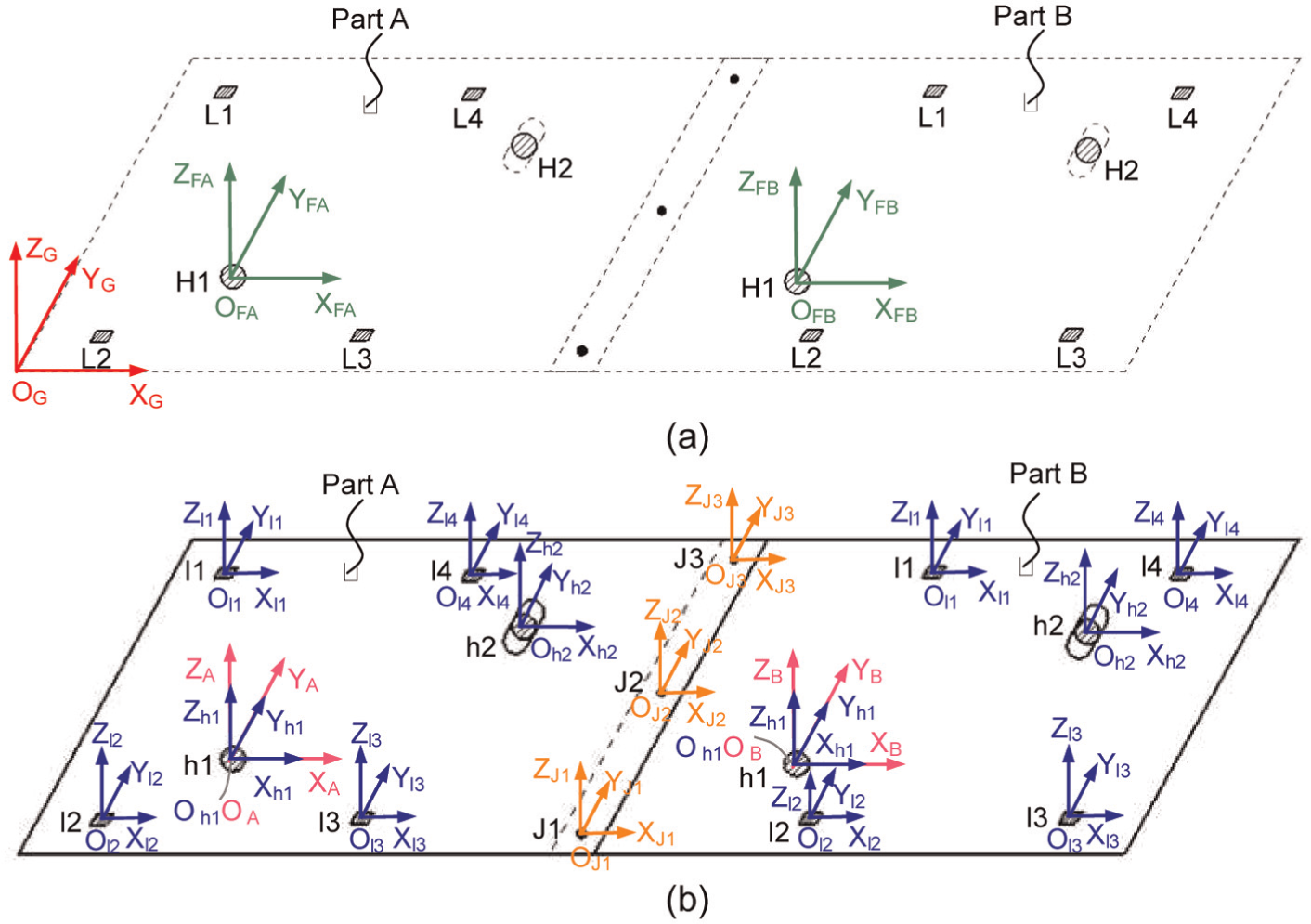
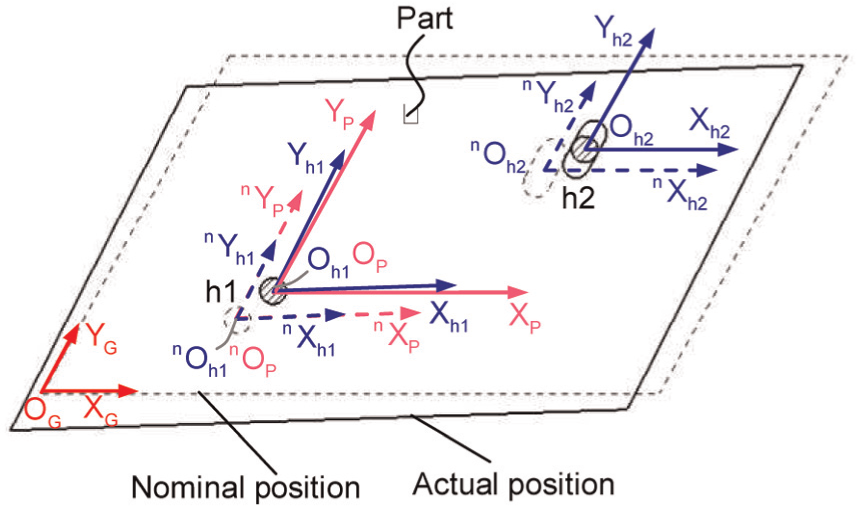
Definitions of coordinate systems: (a) definitions of global coordinate system and fixture coordinate system and (b) definitions of part coordinate system and feature coordinate system.
Fixture coordinate system (FiCS) is a CS associated with a fixture that locates a part. The FiCS is usually set according to the locating scheme. The origin of FiCS is set at the intersection of the locating datum surfaces or their extension of the located part. The Z-axis is normal to the primary datum surface. The X-axis is normal to the secondary datum surface and the Y-axis is normal to the tertiary datum surface.
For sheet metal assembly, the “N-2-1” locating principle is adopted, 22 as shown in Figure 1. N (N ≥ 3) locators (denoted as L1, …, LK, …, LN) are needed on the primary datum to constrain the out-of-plane motion and excessive deformation, where N is determined according to the dimensional specification of sheet metal parts. The pin–hole locating scheme realized by a four-way pin (denoted as H1) inserted in a hole (denoted as h1) and a two-way pin (denoted as H2) inserted in a slot (denoted as h2) is usually adopted as the “2-1” locating principle to constrain the in-plane motion, as shown in Figure 1(a). The FiCSs (marked as OFAXFAYFAZFA and OFBXFBYFBZFB as shown in Figure 1(a)) are defined for the fixtures locating part A and part B, respectively.
Part coordinate system (PCS) is a CS associated with a part. The origin of PCS is at the intersection of the datum surfaces or their extension of the located part. The Z-axis is normal to the primary datum surface, and the X-axis is normal to the secondary datum surface. Then, according to the right-hand rule, the Y-axis can be determined. For sheet metal part, the primary datum surface is the part plane, so the Z-axis direction of PCS is set as the out-of-plane direction. The X- and Y-axes compose the in-plane direction of sheet metal part. In nominal condition, the PCSs (marked as OAXAYAZA and OBXBYBZB as shown in Figure 1(b)) coincide with the corresponding FiCSs.
Feature coordinate system (FeCS) is a CS associated with a feature on a specific part. The origin of an FeCS is set on the geometric center of a part feature. For calculation convenience, the X-, Y-, and Z-axes of FeCS can be set parallel to that of the corresponding PCS, for example, FeCS of feature h1 (marked as Oh1Xh1Yh1Zh1) as shown in Figure 1(b).
Basically, for sheet metal assembly, part features can be classified into two categories according to their functions. Datum features compose the locating datums of a part. For instance, the surface features l1, l2, l3, and l4 compose the primary datum; the hole feature h1 and the slot feature h2 compose the secondary and tertiary datum, respectively, as shown in Figure 1(b). Joint features serve as joint points (such as welding points and riveting points) between parts, for example, J1, J2, and J3, as shown in Figure 1(b).
A structured notation scheme is defined to represent the CSs in this article. There is only one GCS for the assembly process and it is represented as “G.” The nominal FiCS is represented as “n
F,” whereas “F” represents actual FiCS, which may be deviated from the nominal FiCS due to fixture error. In the same way, the nominal PCS is represented as “n
P,” whereas “P” represents actual PCS. The FeCSs of datum features h1 and h2 are represented as “h1” and “h2.” And FeCS of joint feature JK is represented as “JK” (
3D variation representation of sheet metal assembly
It is assumed that the sheet metal parts are primarily planar and the assembly process is an open assembly process. 29 Therefore, 3D variation of sheet metal assembly can be decomposed into in-plane rigid variation and out-of-plane compliant variation. 30,31
In-plane rigid variation is defined as rigid translational and rotational deviation that occurs in the primary datum surface of sheet metal parts, as shown in Figure 2(a). It is rigid-body motion in nature.
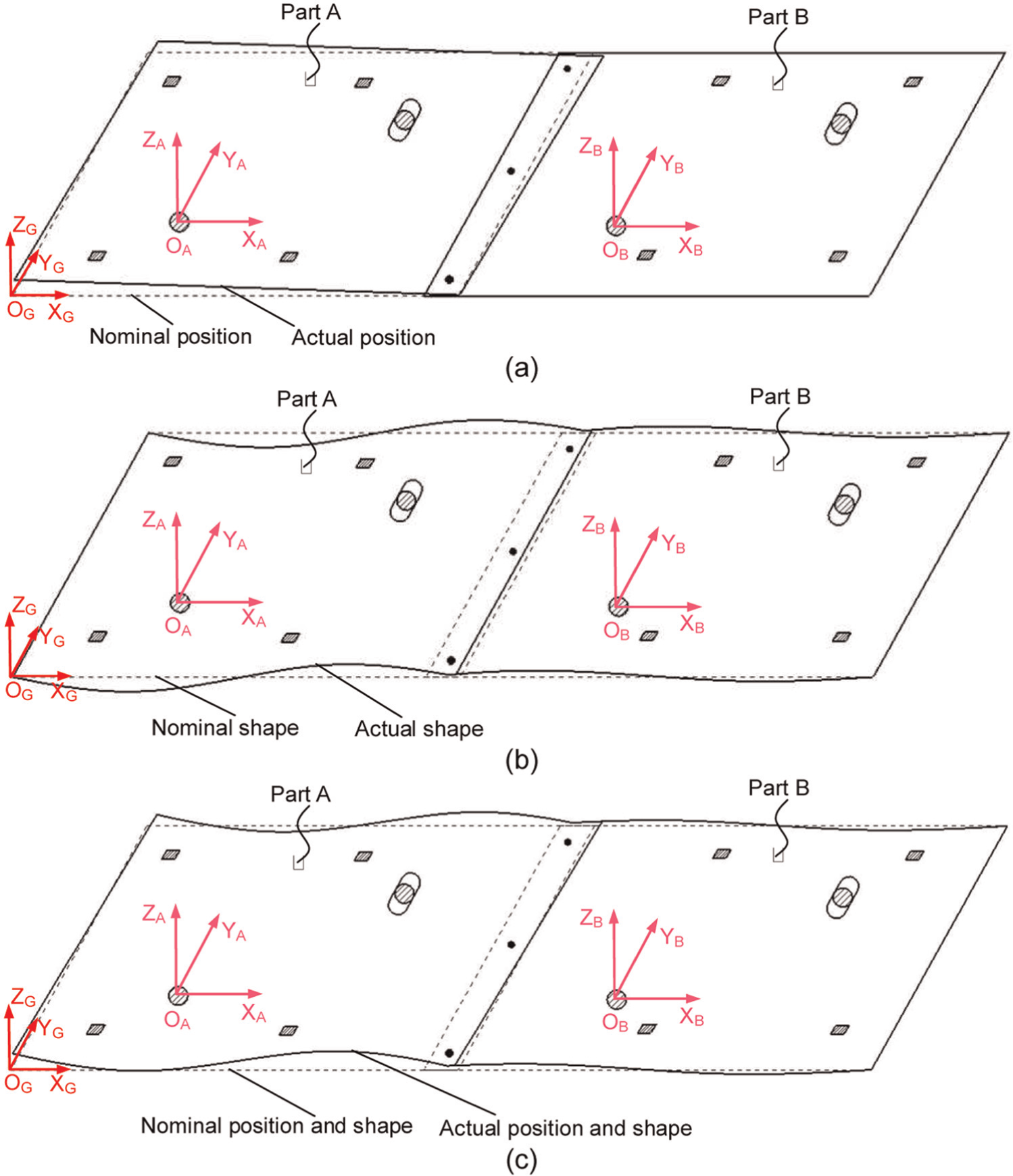
Variation analysis of sheet metal assembly: (a) in-plane rigid variation, (b) out-of-plane compliant variation, and (c) overall variation.
Out-of-plane compliant variation is defined as compliant shape deviation that occurs in the orthogonal direction of the primary datum surface of sheet metal parts, as shown in Figure 2(b). It is deformation in nature.
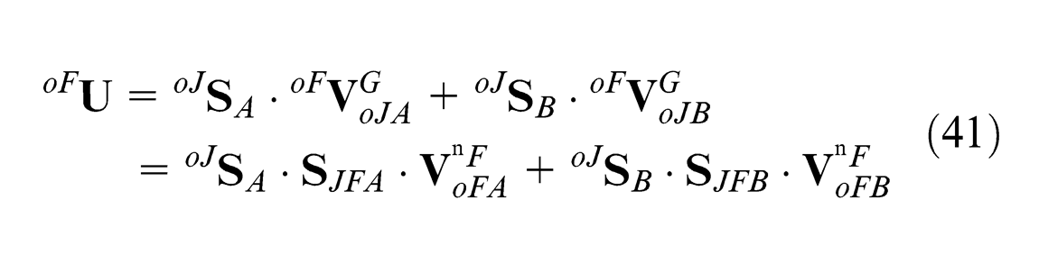
The overall variation of sheet metal assembly (denoted as
In-plane rigid variation representation
In this article, in-plane rigid variation is represented as the in-plane deviations of the PCSs of the sheet metal parts, which are described and calculated by DMV.
When analyzing the in-plane rigid variation of sheet metal assembly, it is assumed that the sheet metal parts are rigid and the impact of the out-of-plane compliant variation is neglected. Therefore, the in-plane rigid variation is analyzed in the 2D plane composed of X- and Y-axes of the PCS, and all the defined CSs become two-dimensional coordinate systems (2D-CSs), as shown in Figure 3.
2D-CSs: (a) 2D-GCS and 2D-FiCS and (b) 2D-PCS and 2D-FeCS.
Since 2D-CS is used to represent each element in sheet metal assembly process, the spatial relationships among different elements can be described by the relationships among different 2D-CSs. The linear transformation between these 2D-CSs can be studied mathematically using homogeneous transformation matrix (HTM). Meanwhile, the in-plane rigid variation of each element in assembly process can be represented as the deviation of its actual 2D-CS with respect to its nominal 2D-CS or another 2D-CS.
The position and orientation of an element can be defined by a coordinate vector with respect to a certain 2D-CS. For example, 2D-CS1 can be defined with respect to 2D-CS2 as
where
A small deviation of any element in sheet metal assembly process can be described by DMV as
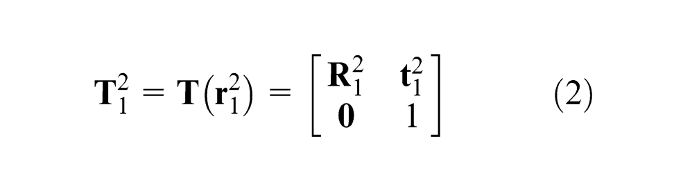
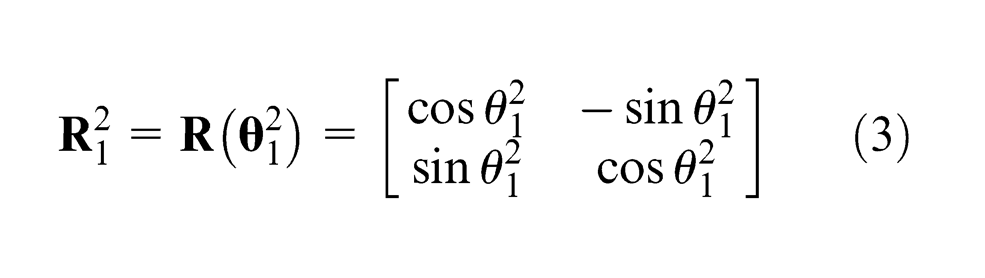
Similarly, the corresponding HTM of
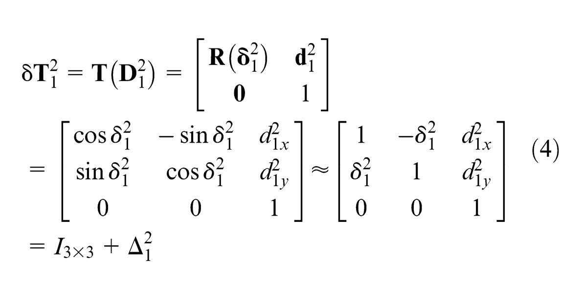
where
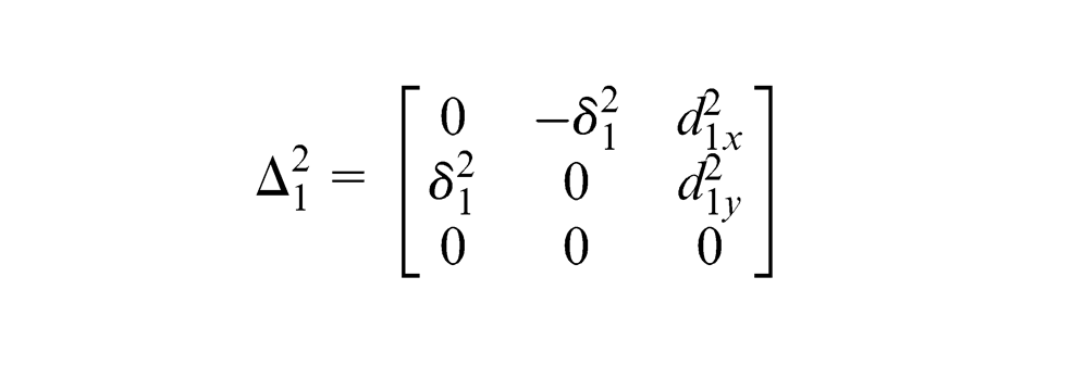
is the differential transformation matrix (DTM).
Then, the actual HTM and the nominal HTM between 2D-CS1 and 2D-CS2 can be related by
Corollary 1
Considering a general transformation between three 2D-CSs, which are 2D-CS1, 2D-CS2 and 2D-CS3. Given the nominal coordinate vectors of
where
This corollary is very useful for transforming deviation between different 2D-CSs. The in-plane rigid variation of sheet metal assembly
Out-of-plane compliant variation representation
Sheet metal parts are very compliant and prone to be deformed in the out-of-plane direction during assembly process. Therefore, the out-of-plane compliant variation cannot be described by the DMV of the PCS kinematically. Instead, an infinite number of discrete points are needed to completely describe the actual part shape. However, in order to balance the accuracy of the model and the calculation efficiency, only some key characteristic points (KCPs) are selected to represent part shape according to the accuracy necessary and the complexity of the part.
Based on the definition of key characteristics (KC) provided by Thornton 32 and Whitney 33 in this article, KCPs are defined as those points on the actual shape of sheet metal assembly, whose variations from nominal significantly affect the final assembly quality and product performance of sheet metal assembly. The variations of KCPs are used to evaluate the assembly variation.
The out-of-plane compliant variation of sheet metal assembly is represented as the vector composed of the out-of-plane deviations of all the selected KCPs. The out-of-plane direction is the Z-axis direction of GCS according to the GCS definition mentioned previously. Therefore, denote the deviation of KCP K in Z-axis direction of GCS as
where Q denotes the total number of selected KCPs.
Unified variation modeling of sheet metal assembly
The in-plane rigid variation is modeled based on DMV and HTM. In the out-of-plane direction, due to the deformation, kinematical variation modeling method is no longer applicable, whereas the mechanistic variation modeling methodology based on MIC 11 is adopted to model the out-of-plane compliant variation. Finally, a unified variation model of sheet metal assembly is built accordingly.
In-plane rigid variation modeling based on DMV and HTM
The in-plane rigid variation of sheet metal part is mainly caused by two types of variation sources: in-plane fixture locators’ deviations and part datum features’ deviations.
Part variation caused by in-plane fixture locators’ deviations
In order to kinematically constrain the in-plane degrees of freedom, two pin locators H1 and H2 are required on the secondary and tertiary datum surfaces of sheet metal parts. These locators are called the in-plane fixture locators (denoted as iF) in this article. If there are deviations in H1 and H2, F will deviate from n
F and P will deviate from n
P in the same direction, as shown in Figure 4. The nominal coordinates of H1 and H2 in nominal 2D-FiCS are given as
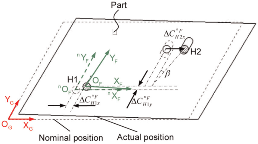
Part variation caused by in-plane fixture locators’ deviations.
Lemma 1
Part variation caused by in-plane fixture locators’ deviations is modeled by DMV of 2D-PCS with respect to 2D-GCS as
where
This lemma can be proved by 2D state space model proposed by Jin and Shi. 4
2. Part variation caused by in-plane datum features’ deviations
Due to manufacturing errors, the in-plane part datum features (denoted as iD) h1 and h2 will deviate from the nominal positions so that part variation will be caused during assembly process, as shown in Figure 5, and it can be derived by Lemma 2 as follows.
Part variation caused by in-plane datum features’ deviations.
Lemma 2
Part variation caused by in-plane datum features’ deviations is modeled by DMV of 2D-PCS with respect to 2D-GCS as
where
Proof
Let q1 and q2 be the datum points touching the in-plane datum features h1 and h2. The nominal coordinates of q1 and q2 in 2D-FiCS are denoted as
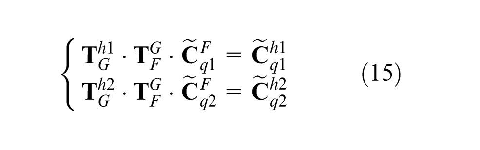
Once the part is located, the locating pins are in touch with the corresponding part datum features. Therefore, datum points q1 and q2 will be right on the part datum features h1 and h2, which leads to the X- and Y-coordinates of q1 with respect to 2D-FeCS of h1 are 0 and the X-coordinate of q2 with respect to 2D-FeCS of h2 is 0. Denoting
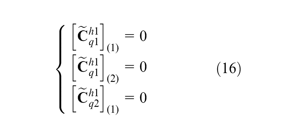
In section “In-plane rigid variation representation,” some properties of HTM for 2D-CS are given, which are similar to the properties of HTM for 3D-CS. Therefore, with the similar method as Zhou et al., 34 equations (15) and (16) can be deduced to equation (17) as
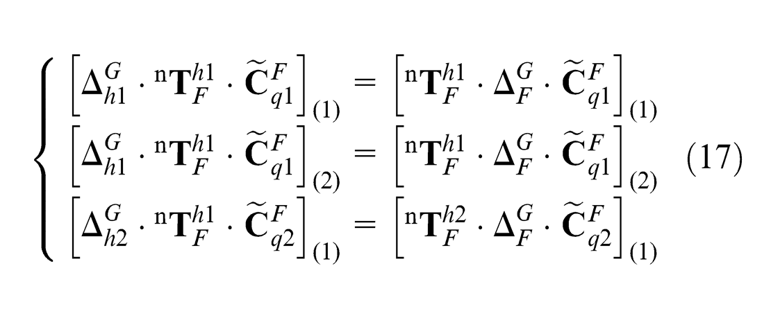
Given the nominal coordinates of q1 and q2 with respect to 2D-FiCS as
And nominal HTM of 2D-FiCS with respect to the 2D-FeCSs of part datum features h1 and h2 as
The solution of equation (17) can be obtained as

According to Corollary 1 mentioned in section “In-plane rigid variation representation,” it can be obtained that
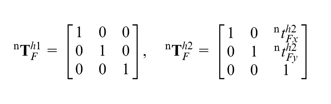
It is assumed that deviation of F from n
F is very small, and
Since n P and n F coincide with each other, the HTM between them is
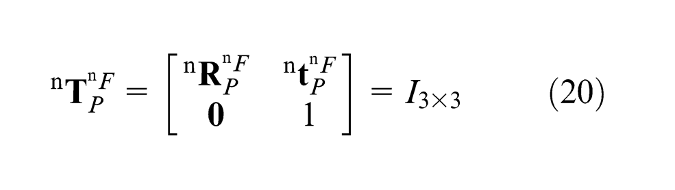
Then, we can obtain that
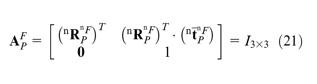
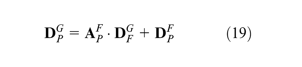
It is assumed that the position and orientation of part in the in-plane direction are fixed after located on the fixture, that is

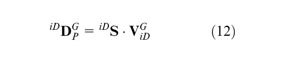
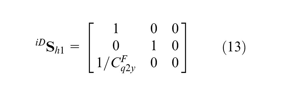
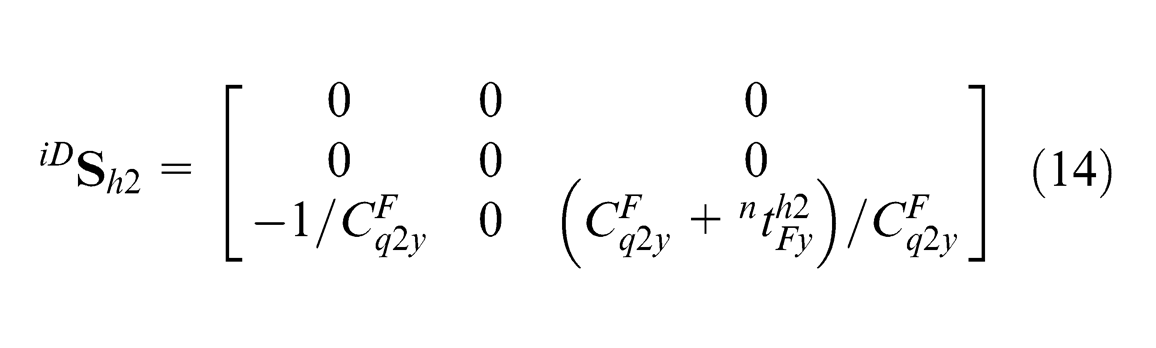
Substituting equations (21) and (22) into equation (19), it can be obtained that

By combining equations (23) and (18), equation (12) is obtained.
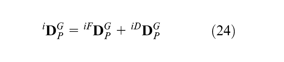
3. Overall in-plane rigid variation of sheet metal assembly
Lemma 3
The overall in-plane rigid variation of sheet metal part with respect to 2D-GCS is the sum of part variation caused by in-plane fixture locators’ deviations and part variation caused by datum features’ deviations as
The overall in-plane rigid variation of sheet metal assembly is expressed as the stack-up of DMVs of the actual 2D-PCSs of both part A and part B as equation (7), where
Out-of-plane compliant variation modeling based on MIC
To build the out-of-plane compliant variation model, some assumptions are made: The effect of the in-plane rigid variation is neglected, deformation is in the linear elastic range, material is isotropic, fixtures and joint tools are rigid, no thermal deformation occurs, and stiffness matrix remains constant for deformed part shape.
The out-of-plane compliant variation of sheet metal assembly is contributed mainly by two types of sources: joint features’ deviations and out-of-plane fixture locators’ deviations. Since the Z-axes of all the CSs are defined as the out-of-plane direction, the out-of-plane compliant variation of sheet metal assembly is calculated in the GCS and no CS transformation is necessary.
Assembly variation caused by joint features’ deviations
Based on MIC, the out-of-plane compliant variation of sheet metal assembly caused by part joint features’ deviations can be derived by Lemma 4 as follows.
Lemma 4
For a sheet metal assembly composed of part A and part B, the assembly variation caused by joint features’ deviations is represented as the deviations of selected KCPs in Z-axis direction of GCS as
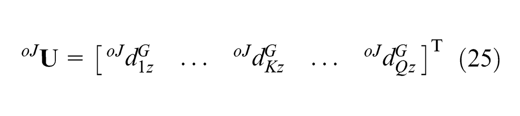
and it can be calculated as
where

where
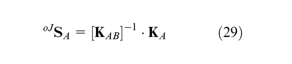
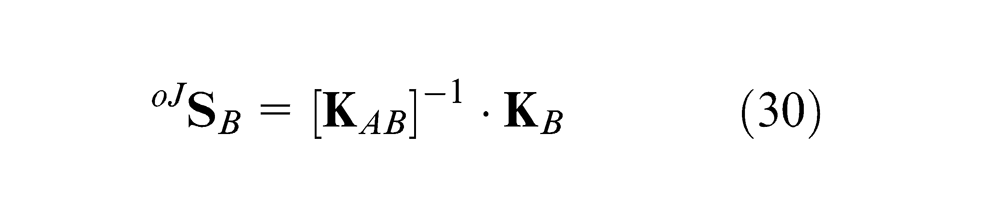
where
2. Assembly variation caused by out-of-plane fixture locators’ deviations
In order to constrain the kinematical motion and excessive deformation in the out-of-plane direction, N (N ≥ 3) locators are required on the primary datum surfaces of sheet metal parts. These locators are called the out-of-plane fixture locators (denoted as oF) in this article. The out-of-plane compliant variation of sheet metal assembly caused by out-of-plane fixture locators’ deviations can be derived by Lemma 5 as follows.
Lemma 5
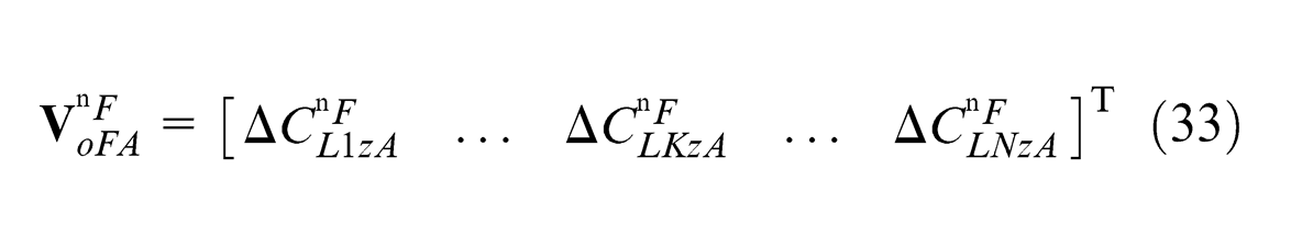
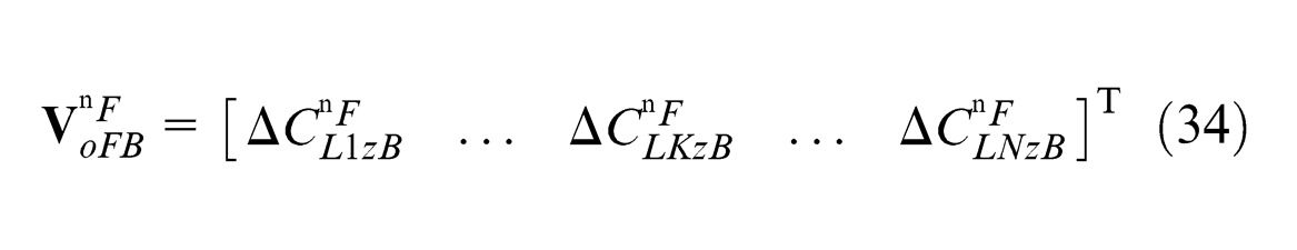
For a sheet metal assembly composed of part A and part B, the assembly variation caused by the out-of-plane fixture locators’ deviation is represented as the deviations of selected KCPs in Z-axis direction of GCS as
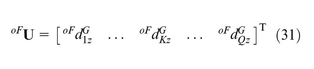
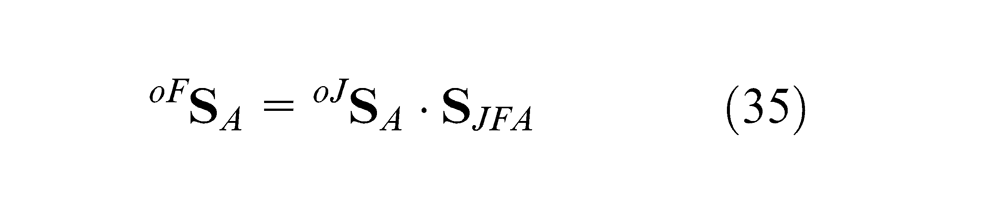
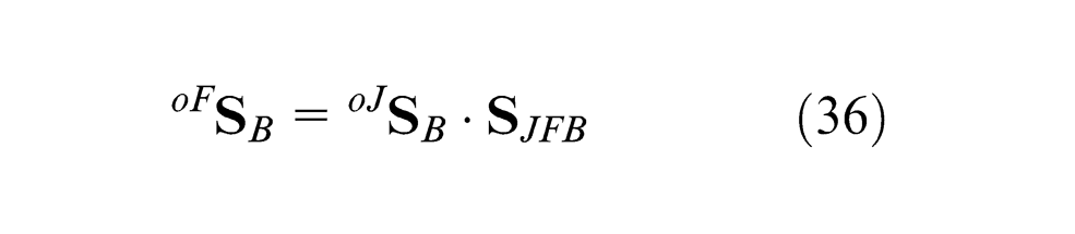
and it can be calculated as
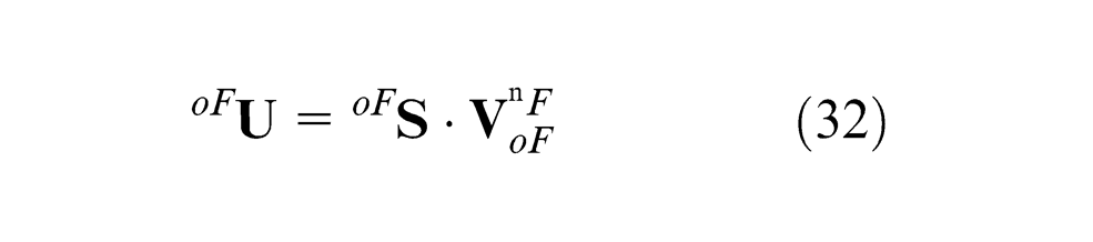
where
where
where
Proof
It is assumed that nominal FiCS has no deviation with respect to GCS, so it can be obtained that
By applying MIC, the joint features’ deviations of parts due to the out-of-plane fixture locators’ deviations before joining operation can be obtained as
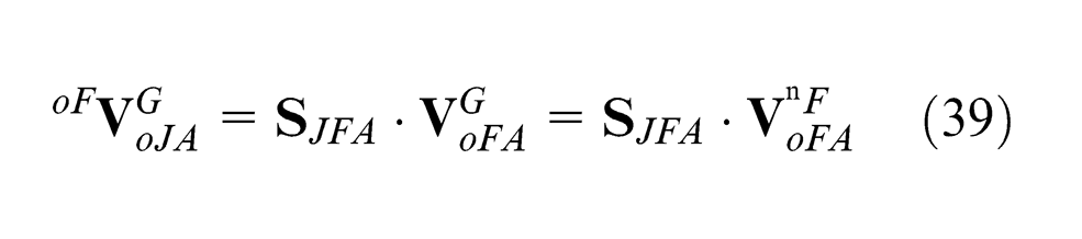
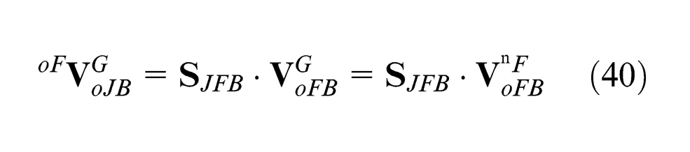
By applying Lemma 4, it can be obtained that
Denote
3. Overall out-of-plane compliant variation of sheet metal assembly
Lemma 6
The overall out-of-plane compliant variation of sheet metal assembly is the sum of assembly variation caused by joint features’ deviations and assembly variation caused by the out-of-plane fixture locators’ deviations as
where
Unified variation modeling of sheet metal assembly
In this article, three types of variation sources that are fixture locators’ deviations including in-plane fixture locators’ deviations (denoted as
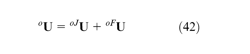
Affected by the variation sources, sheet metal assembly will have dimensional variation. The overall 3D variation of sheet metal assembly is the combination of both the in-plane rigid variation and the out-of-plane compliant variation, represented as
Case study
In this section, the unified variation model of sheet metal assembly is illustrated by a case study. Two sheet metal plates are joined together at one assembly station, as shown in Figure 6. Part A has dimensions of
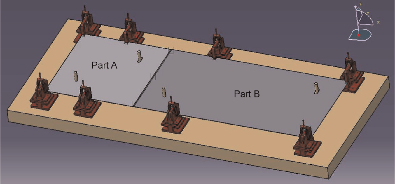
Illustration of sheet metal assembly in CATIA V5.
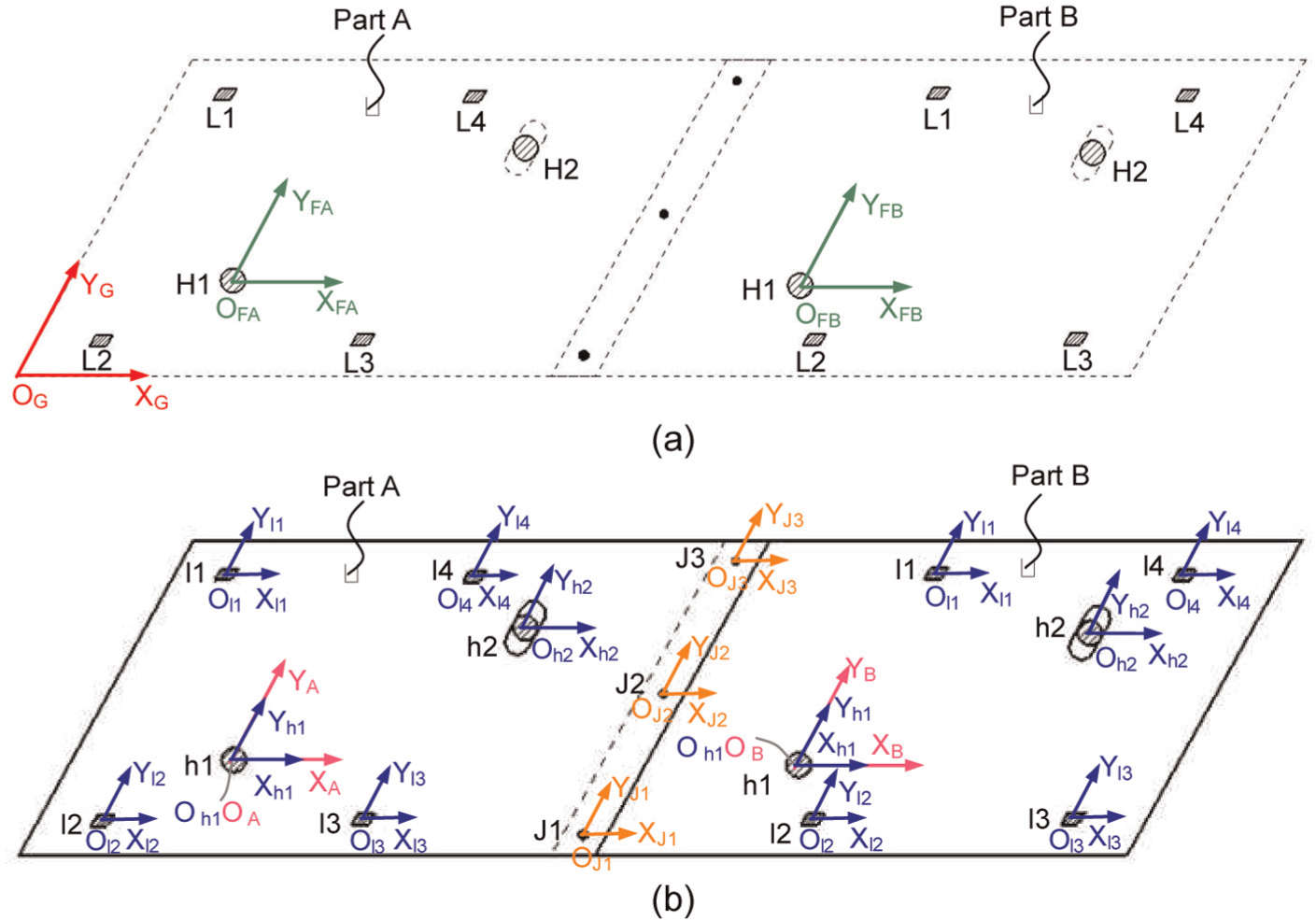
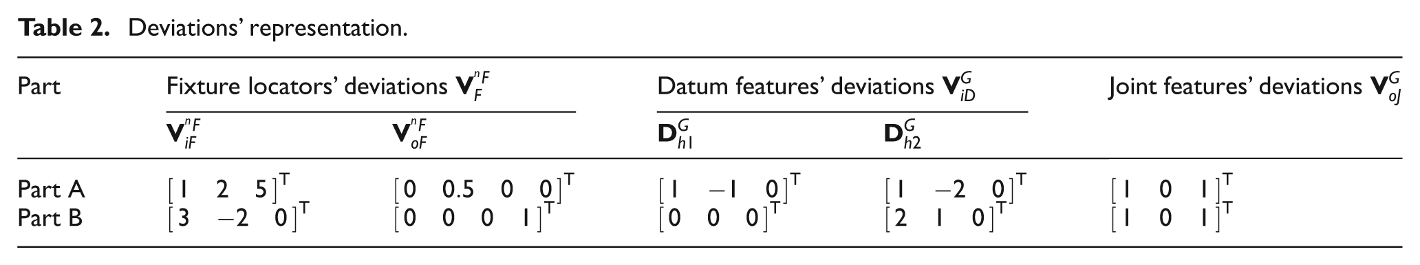
The CSs of sheet metal assembly are defined, as shown in Figure 7. The geometric information of the parts and assembly process are summarized in Tables 1–3. The origin of GCS is set at the lower left corner of part A as shown in Figure 7(a). FiCSs, PCSs, and FeCSs of part A and part B are defined, and their 2D vectorial representations with respect to GCS in the in-plane direction are listed in Table 1. The nominal coordinates of fixture locators with respect to the nominal FiCS can be obtained according to the dimensional vectorial representations of FiCSs and FeCSs of datum features with respect to GCS given in Table 1. Table 2 presents variation sources for each part. Table 3 presents the coordinates of KCPs which are used to evaluate the out-of-plane compliant variation of the sheet metal assembly with respect to GCS.
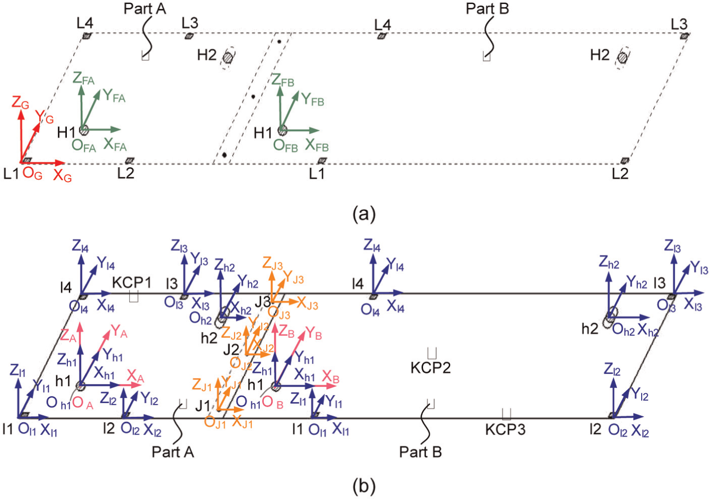
Coordinate systems of sheet metal assembly: (a) global coordinate system and fixture coordinate system of sheet metal assembly and (b) part coordinate system and feature coordinate system of sheet metal assembly.
Vectorial representation of fixture, part, and feature coordinate systems (with respect to GCS).
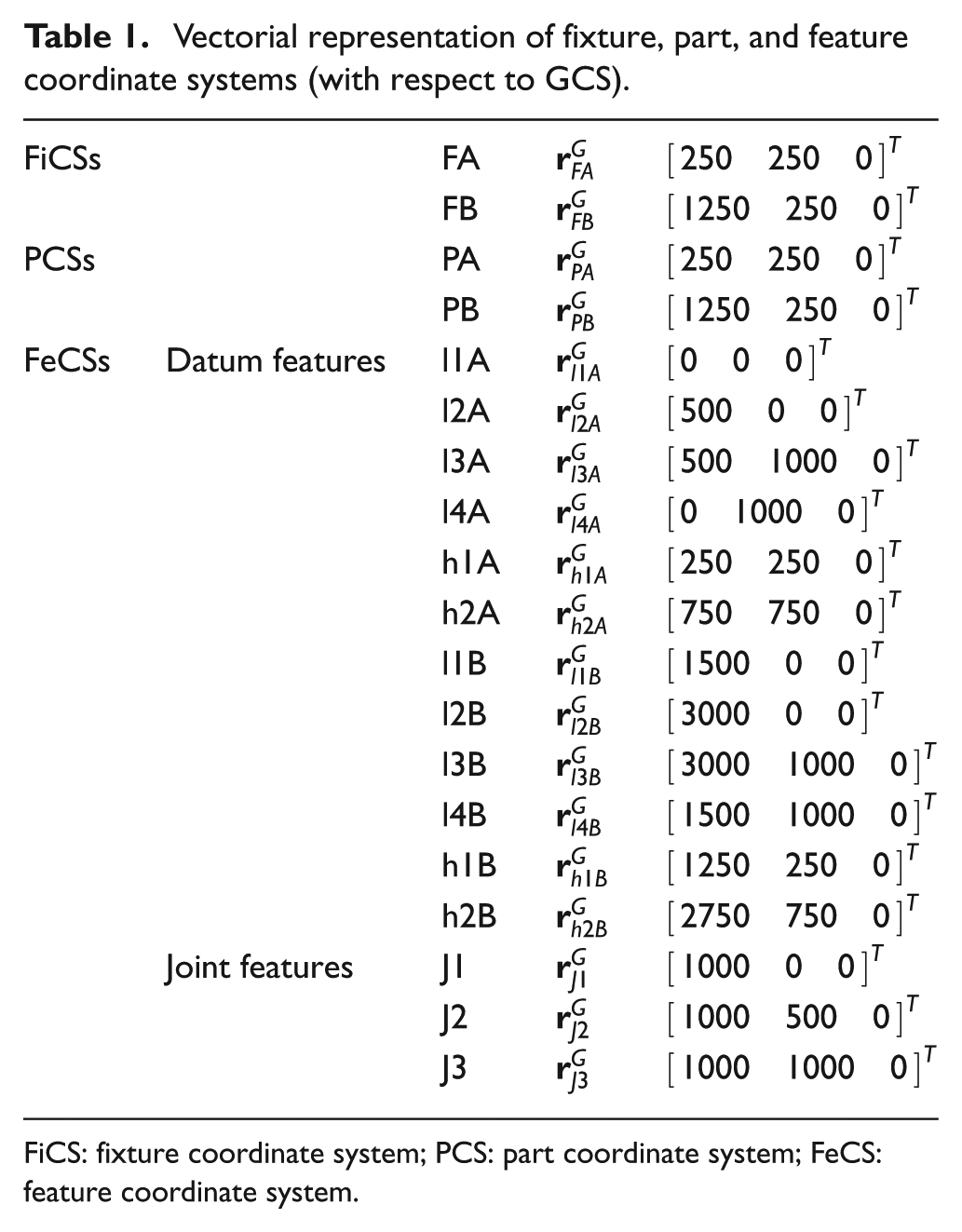
FiCS: fixture coordinate system; PCS: part coordinate system; FeCS: feature coordinate system.
Deviations’ representation.
KCPs’ vectorial representation.
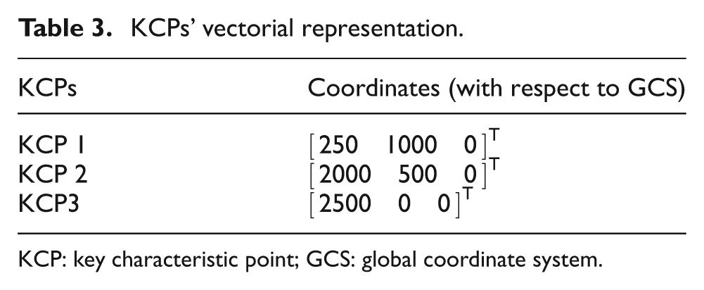
KCP: key characteristic point; GCS: global coordinate system.
With the given data mentioned above, the overall 3D variation of the study case sheet metal assembly can be calculated by the unified variation model described in section “Unified variation modeling of sheet metal assembly,” and the final result is shown as follows

where
The unified variation model can be used in 3D variation analysis of sheet metal assembly considering rigid and compliant variation simultaneously so as to better evaluate the dimensional quality of sheet metal assembly. Since the model is linear and only five runs of FEM are needed for sensitivity matrices, the unified variation model proposed in this article is quite efficient for 3D variation analysis of deformable sheet metal assembly.
Conclusion and future work
A unified variation model of sheet metal assembly is developed in this article. The overall 3D variation is decomposed into rigid variation in the in-plane direction and compliant variation in the out-of-plane direction. The in-plane rigid variation is analyzed based on DMV and HTM, and the out-of-plane compliant variation is analyzed based on MIC. Three types of variation sources related to both product and process information are considered (fixture locators’ deviations, datum features’ deviations, and joint features’ deviations).
The advantages of the proposed model include the following: better evaluation of dimensional quality of sheet metal assembly with both in-plane rigid variation and out-of-plane compliant variation considered, it has an analytical linear model with computational efficiency, and it provides the basis for a unified assembly model for variation propagation analysis in multistation assembly process of sheet metal parts. For more generality and applicability, it is necessary to establish unified variation model for sheet metal parts with 3D generic free surfaces. The presented work is an initial and primary step toward the development of this more generic model and it will be researched in future work.
The proposed model has various potential applications for dimensional quality assurance of sheet metal assembly in industries such as aerospace, automobile, and electronics. It allows variation prediction, tolerance synthesis, and tolerance analysis for sheet metal assembly process. Since the relationship between the product quality and process variables is established, variation source identification can be conducted. The coefficients of the model are the functions of product/process design parameters, so the proposed model can be applied to design optimization (i.e. fixture layout optimization) with high computation efficiency. In this way, the dimensional quality assurance is moved to the early stage of production so as to reinforce the total quality management. Since datum features’ deviations and joint features’ deviations that are determined by part manufacturing process are modeled, it helps tolerance synthesis of sheet metal parts in upstream part manufacturing stage to reduce manufacturing cost and improve dimensional quality. The approach proposed in this article can be automated and implemented in commercial software such as CATIA V5 (for instance).
Footnotes
Appendix 1
Declaration of conflicting interests
The authors declare that there is no conflict of interest.
Funding
This work was partially supported by the National Natural Science Foundation of China (grant no. 51075022) and Ministry Project on Digital Assembly Process Planning. This work was also supported by Beijing Municipal Education Commission (Build a Project).