
Abstract
This article presents a comprehensive analysis of surface characteristics and drilling performance of uncoated and coated tungsten carbide drills. The single- and double-layer coatings of TiN, TiAlN and AlCrN were examined in terms of surface roughness, microhardness and crack resistance. In addition, drilling torque and thrust force were experimentally measured and compared to the developed models based on the drilling mechanics and drill geometries. Tool wear and hole surface roughness were also considered to assess the machining performance of different coated tools. The results revealed that all coated drills can offer better cut surface quality, 28% lower cutting loads and longer tool life than the uncoated drills. Although AlCrN was found to be the hardest coating material among the others, it caused large wear on the cutting edges and poor surface roughness of produced holes. The lowest torque and thrust force were achievable using TiN-coated drill, while the use of TiAlN coating resulted in the lowest surface roughness and smallest tool wear. Furthermore, the drilling torque and thrust force model developed in this study were found to correspond to the experimental measures with the average error of 8.4%. The findings of this work could facilitate the selection of coating materials to advance the machining performance.
Introduction
Cutting tool life and machining performance have been of great concern in manufacturing industries, where long tool life, good surface finish and high material removal rate are desired to produce parts economically and efficiently. Helical-fluted twist drill is the most basic tool for making holes, in which two cutting edges at the drill lips are responsible to rotationally shear off work material and deepen hole with a given feed rate. Tungsten carbide (WC) drills are typically used for making holes in various metals since the hardness of WC can withstand the formation of tool wear under high machining loads, thus maintaining the cutting performance. Besides using harder tool materials to prolong the tool life, some coating materials can be applied as a thin film on the tool surface to gain higher surface hardness, better wear resistance and lesser friction coefficient of cutting tools.1–3
TiN, TiAlN and AlCrN are normally used as coating materials for enhancing the tribological properties of workpiece. These coating materials can find large applications in tooling industries, where the service life of equipment is highly subjected to the resistance to deformation, crack and wear of workpiece surface under static and/or dynamic thermo-mechanical loads. The coating materials can deposit and form either single- or multi-layer coatings on the tool surface with the aid of some vapor deposition techniques. Fox-Rabinovich et al. 4 compare the microhardness, elastic modulus and crack resistance of TiAlN- and AlCrN-coated WC tools, and the AlCrN-coated tool exhibits better wear and crack resistances than TiAlN. In addition, the AlCrN-coated tool provides smoother cut surface and lower coefficient of friction than TiAlN as reported by Mo et al. 5 The good wear resistance of AlCrN is mainly due to the formation of chrome oxides and alumina that promotes anti-oxidation and anti-spalling properties, thus limiting the wear formation. However, the low thermal conductivity of AlCrN can introduce high contact temperature 6 and in turn cause some thermal effects to the coating and another material being in contact. The frictional and wear behavior of AlCrN, TiN and TiAlN coatings in air and vacuum environments was investigated by Liew et al., 7 noting that TiN provides the lowest friction coefficient among the others in vacuum while the oxidation of AlCrN in air makes it the most lubricous coating. However, Liew et al. further found that the friction coefficient of AlCrN significantly increases with the sliding speed. Although AlCrN coating can offer better wear resistance and lower coefficient of friction than many coating materials, Sousa et al. 8 reported that the drilling torque and thrust force induced by AlCrN-coated drill are higher than TiAlN-coated tool. To further advance both wear resistance and cutting performance, Vannan et al. 9 deposited AlCrN and TiAlN as a bilayer coating to a high-speed steel-cutting tool, and the results indicate that the bilayer coating can reduce tool wear and provide good cut surface of workpiece. Furthermore, this bilayer coating provides high resistance to plastic deformation due to its high Young’s modulus. 10 In addition to the TiN, TiAlN and AlCrN coatings, Xu et al. 2 found that diamond-coated carbide tool can prolong the tool life for 10 times compared to the TiAlN-coated tool in the machining of graphite. However, the diamond coating easily delaminates and chips after being used for a period of time, thereby rapidly increasing cutting force and tool wear. Plasma nitriding process is also applied to harden the high-speed steel drills as reported by Ucun and Kaplan 3 and Das et al. 11 Nevertheless, its tribological properties are not remarkably better than those offered by the TiN, TiAlN and AlCrN coatings.
According to the review of literature noted above, the investigations of coating materials are mostly done through some characterization techniques to reveal the mechanical and wear behavior of coating materials while their effects on machining performance have rarely been analyzed with regard to the machining mechanics. By considering the drilling process, the effect of friction coefficient on drilling mechanics caused by different coating materials has not clearly been revealed, although a number of research works interestingly propose the empirical 12 and analytical13–15 models for prediction of cutting loads. Therefore, a comprehensive study of coating and its characteristics associated with the drilling mechanics is necessary to provide a better insight into the process.
This study presents the characteristics of coating layers and their effects on drilling performance. Three famous coating materials, that is, TiN, TiAlN and AlCrN, were considered in this work to deposit on the surface of WC drills with single- and double-layer approaches. The investigations were performed through the theoretical and experimental analyses of drilling mechanics. The implication of this study could facilitate the selection of coating materials to advance the machining performance.
Mechanics of drilling
Drill lips are responsible for shearing off work material while they are rotating about the drill axis and feeding into the workpiece. With regard to the drill geometry shown in Figure 1, the cutting speed as well as cutting force (Fc) vector is not perpendicular to the drill lips, but it inclines with an angle i called the angle of obliquity.
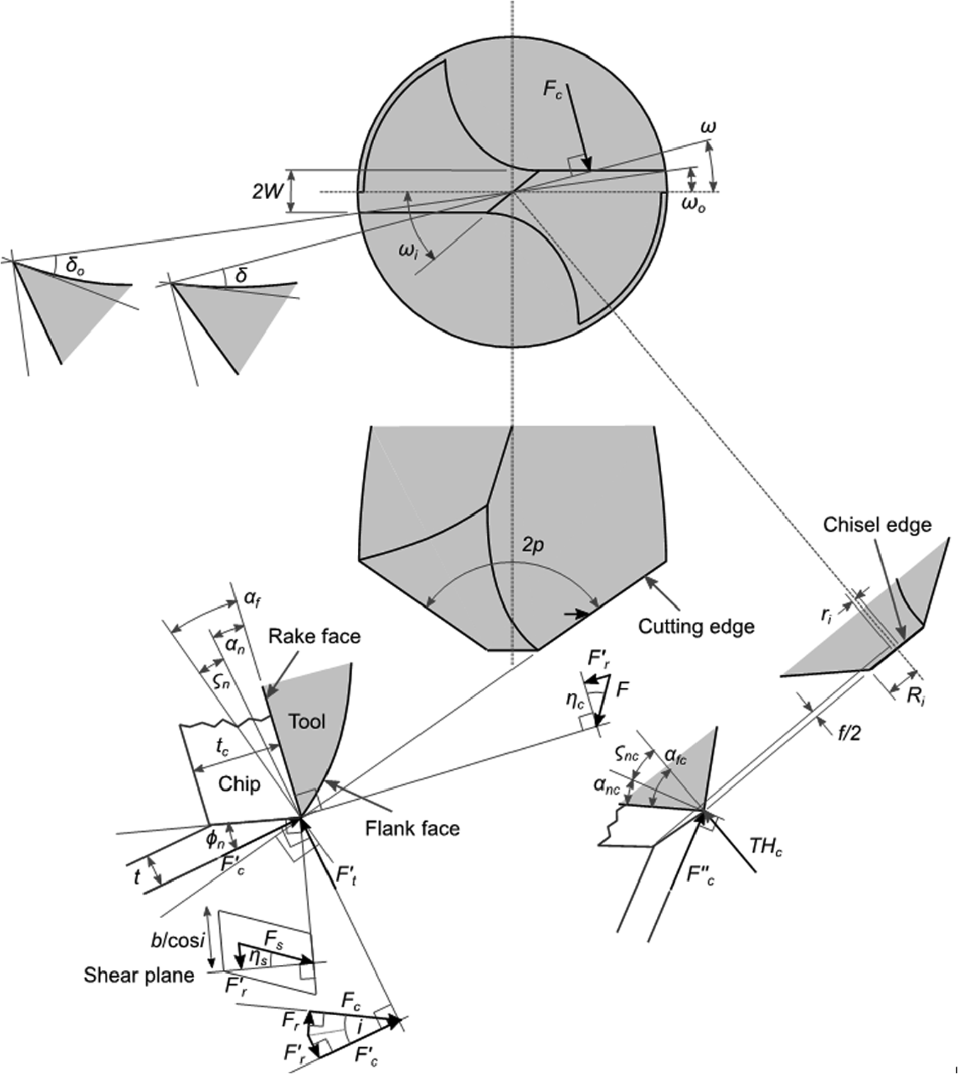
Drill geometry and force components.
The angle of obliquity is expressed as

where 2p and ω are point and web angles of drill, respectively. The web angle (ω) is

2W and r are lip spacing and radial distance from the drill axis. According to equations (1) and (2), the angle i is changed with r. Thereby, the Fc acting along the drill lips are also dependent on r. The total Fc can be computed by discretizing the drill lips into many small elements and then integrating all the Fc calculated from each element. The width of cutting edge (b) is defined using
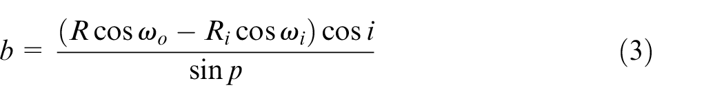
where R and ωo are the radius of drill and web angle at the outer most of cutting edge (R). Ri and ωi are hole radius previously drilled in the workpiece and web angle at Ri. If there is no hole earlier drilled, Ri and ωi are subjected to the size and orientation of chisel edge which are expressed as

With the aid of Figure 1, the normal rake angle (αn) of cutting edge can be determined by

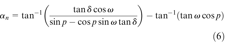
where δ is helix angle at the middle of cutting edge element. Since the helix angle changes with the radial distance (r), the angle can be expressed as

where δo is the helix angle at the outer most of cutting edge (R). To determine the drilling force, some assumptions are applied to simplify the analysis: (1) the drill lips are deadly sharp; (2) there is no friction between cutting tool and hole surface; (3) the cutting of material occurs in a thin shear zone; (4) cutting velocity (V), chip velocity (Vc) and shear velocity (Vs) of each cutting edge element are located on the same plane; and (5) collinearity condition is applied to the chip flow direction and orientation of friction force so as the shear velocity and shear force. Therefore, oblique cutting scheme is considered to analyze the drilling mechanics.
The uncut chip thickness (t) can be determined using

where f is feed per revolution. According to the oblique cutting models, the shear force (Fs) and friction force (F) can be calculated using
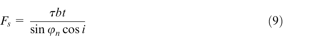
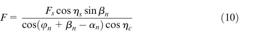
where τ, ϕn, ηs, βn and ηc are shear strength of work material, shear angle on the normal plane, orientation of shear force on the shear plane, friction angle on the normal plane and chip flow angle, respectively. The normal shear angle, ϕn, is expressed as
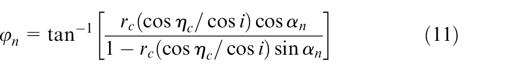
rc is a cut ratio which is a function of uncut chip thickness (t) and chip thickness (tc); that is

Regarding Figure 1, ηs and βn can be determined using
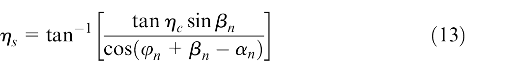

where β is friction angle and μ is friction coefficient between cut chip and rake face of cutting tool.
Three force components in machining process are cutting force (Fc), thrust force (Ft) and radial force (Fr), and they can be derived as
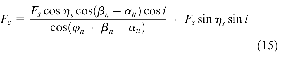
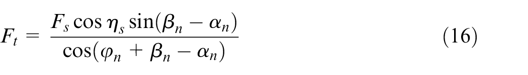
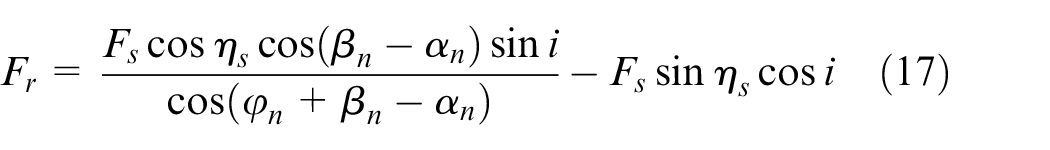
By substituting equations (8) and (9) into equations (15)–(17), the three force components can be rewritten as
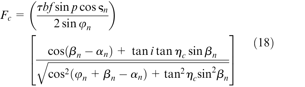
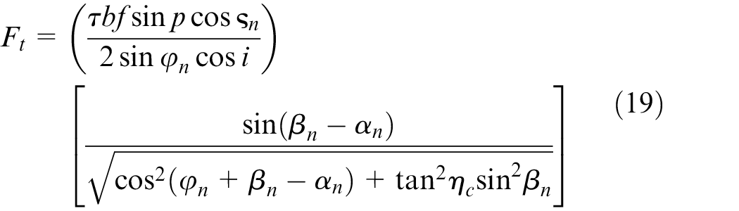
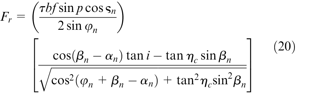
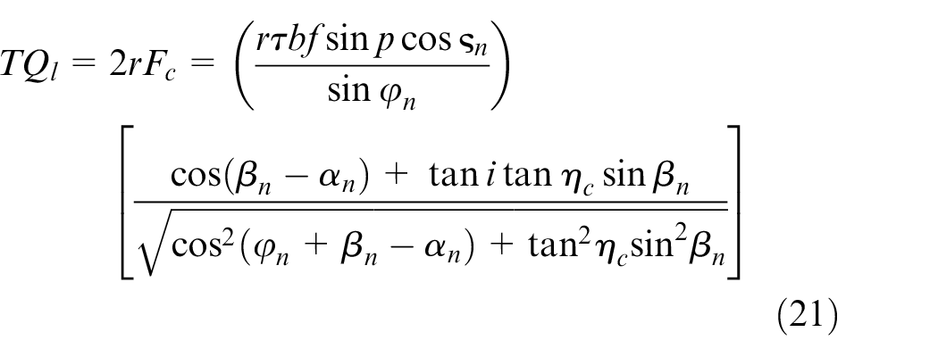
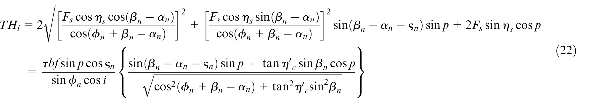
Based on the three components of force derived above, torque (TQl) and thrust force (THl) occurred on the drill lips can be calculated using
In addition to the drill lips, torque and thrust force also take place on the drill chisel. Since the chisel is located at the drill center with very small radial distance from the drill axis, torque developed on the chisel (TQc) can be neglected. However, thrust force acting on the chisel is of significance for resisting the drill feeding toward the workpiece. Regarding Figure 1, the chisel typically engages the work material with negative rake angle (αnc), and the machining forces cannot be estimated correctly using the Merchant model 16 as expressed in equations (18)–(20). Moreover, the center of chisel tends to indent into the work material rather than undergoing the shearing of material element. The exact radius of indentation zone (ri) is basically difficult to be defined but it can be estimated using 17

Therefore, a half-length chisel (bc) that is responsible for shearing is expressed as

The thrust force induced by the chisel can be determined using
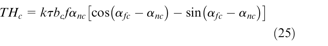

where k is an empirical constant.
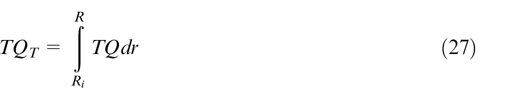
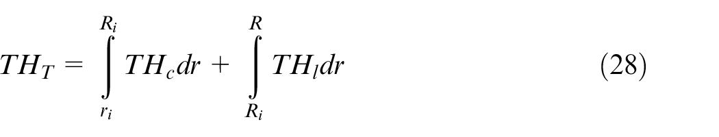
Since the magnitude of torque and thrust force is changed with the radial distance from the drill axis, the total torque (TQT) and thrust force (THT) are thus written as the following integral forms
Materials and methods
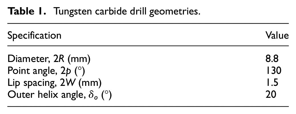
Helical-fluted twist drills used in this study were uncoated and coated WC (NF-GDN, OSG Corp., Japan), and the important drill geometries are given in Table 1 and Figure 2. The coated drills were prepared using physical vapor deposition (PVD) technique associated with the arc evaporation system. Single-layer coating of TiN, TiAlN and AlCrN and double-layer coating of AlCrN/TiN and AlCrN/TiAlN were applied to the drill surface as shown in Figure 3. Specifically for the double-layer coating, AlCrN was used as the top coat, since its hardness is greater than TiN and TiAlN.4,7 With this arrangement, it is believed that the drill surface could be of high resistance to wear. The thickness of each coating layer is presented in Figure 3(f), indicating that the thickness of single-layer coatings is 2–3 μm and it is about 5 μm for the double-layer coatings.
Tungsten carbide drill geometries.
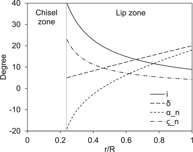
Inclination angle (i), helix angle (δ), normal rake angle (αn) and cutting force angle (ςn) of drill under different r/R.
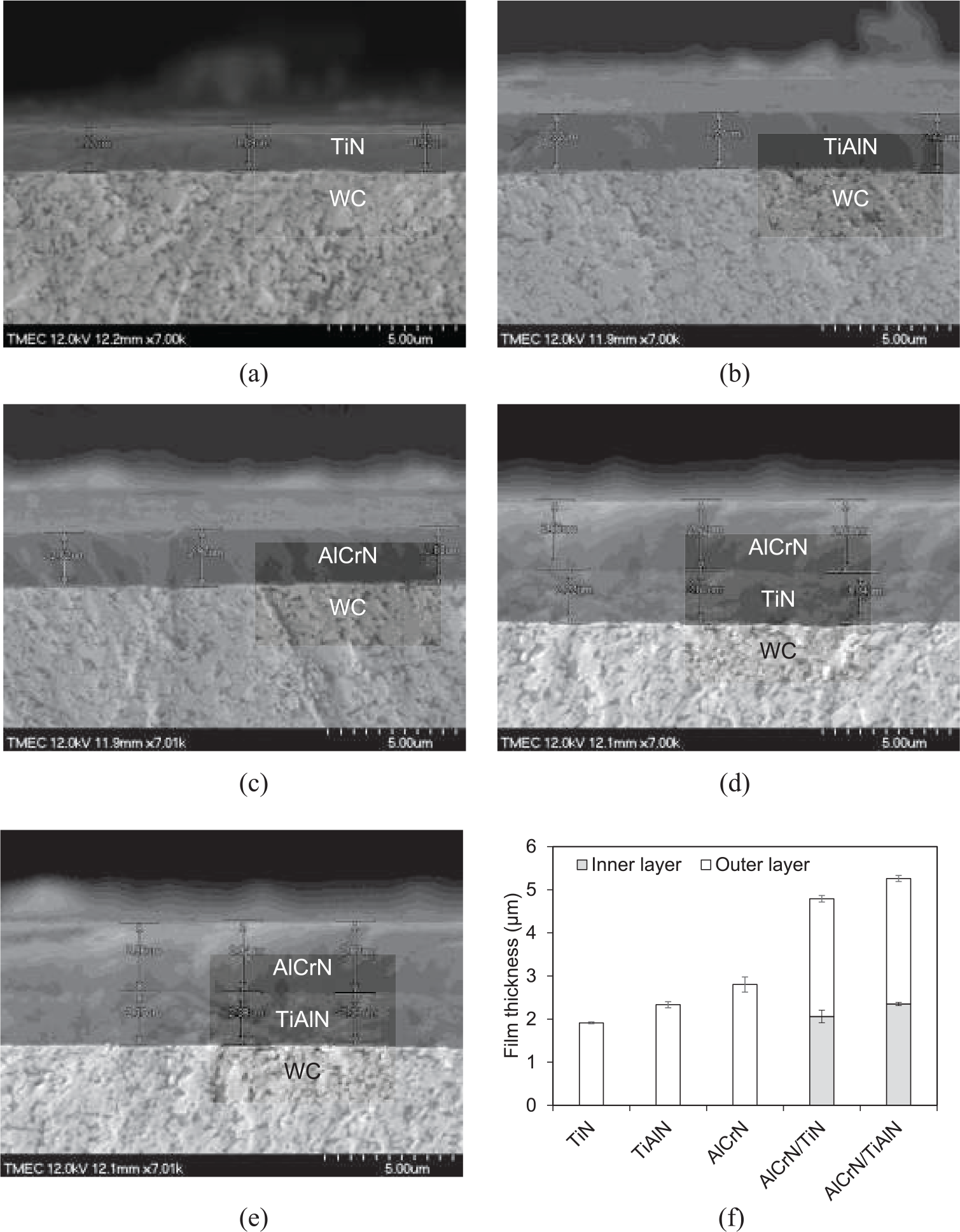
(a)–(e) Cross-section and (f) thickness of coatings of WC drills.
Two major investigations were carried out in this work to understand the characteristics of coatings and the machining performance of uncoated and coated drills. Microhardness, surface roughness and adhesion force of coating layers were quantified in the first set of this study. The microhardness was measured at the top surface of each sample, in which a diamond indenter was applied with a load of 50 gf for 10 s. The average surface roughness (Ra) of top coat was examined using a profilometer (Surfcom 480A; Carl Zeiss, Germany) with the cut-off distance of 0.8 mm. The adhesion force of coatings was evaluated through a scratch test using CSM Revetest Macro Scratch Tester. A diamond indenter having a radius of 200 μm pressed down toward the work sample, where a mechanical load was linearly varied from 0 to 100 N with the increasing rate of 100 N/min. The indenter was moved for a 10-mm distance with the scratching speed of 10 mm/min. When the coating started to be deformed, cracked and delaminated, the applied force was read and noted as Lc1, Lc2 and Lc3, respectively.
To realize the drilling performance, the uncoated and coated tools were employed to drill 400 blind holes consecutively with the depth of 10 mm each in a medium carbon steel (AISI 1050) block. A computer numerical control (CNC) machining center (HAAS VF3, Haas Automation, Inc., USA) was used to perform the dry drilling tests using the rotational speed of 2170 r/min, that is, the average cutting speed of 30 m/min at the middle of cutting edge (R/2) and feed rate of 325.5 mm/min. This drilling condition was selected in accordance with the drill manufacturer’s recommended condition. The drilling forces along x, y and z directions as well as a moment about drill axis were measured using a dynamometer (Kistler, Switzerland). An optical microscope (VHX-5000, Keyence, Japan) was employed to observe and measure wear in the flank and rake faces of drills. The average surface roughness (Ra) of drilled holes was quantified using a profilometer.
Results and discussion
Characterizations of coatings
Microhardness of coatings is shown in Figure 4(a), indicating that AlCrN is harder than TiN and TiAlN. The average hardness of AlCrN was 3235 HV while the hardness of TiN and TiAlN was 1678 and 2759 HV, respectively. Since the microhardness was measured at the top surface of coating, the measurement for the double-layer coatings were taken at the top coat which was the AlCrN layer. By comparing to the average hardness of WC substrate (1359 HV), TiN, TiAlN and AlCrN were harder than the substrate by 23.4%, 102.9% and 138%, respectively. The average surface roughness (Ra) of coatings is presented in Figure 4(b), showing the roughness increases from 0.12 μm for the uncoated WC substrate to 0.15, 0.13, 0.17, 0.19 and 0.20 μm for TiN, TiAlN, AlCrN, AlCrN/TiN and AlCrN/TiAlN, respectively.
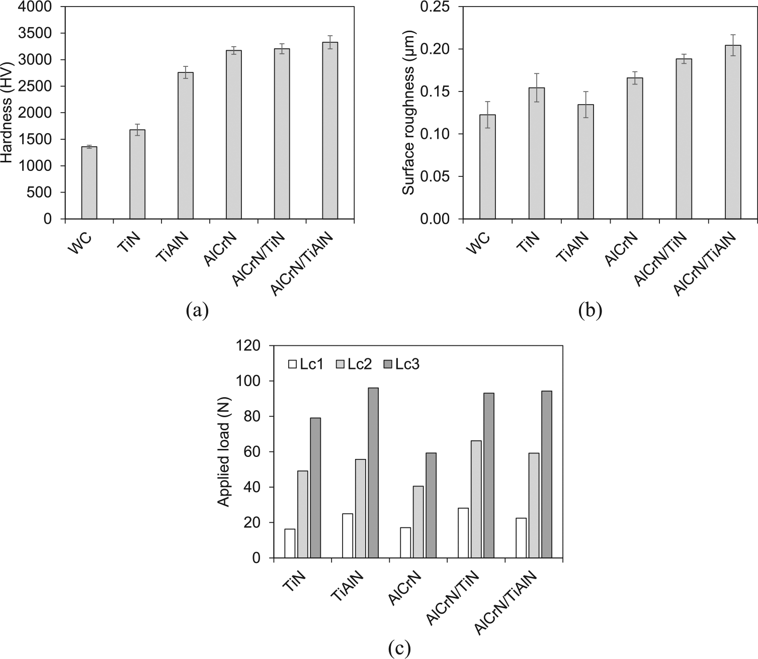
Characteristics of uncoated and coated drill surfaces: (a) hardness, (b) surface roughness and (c) applied load of scratch test.
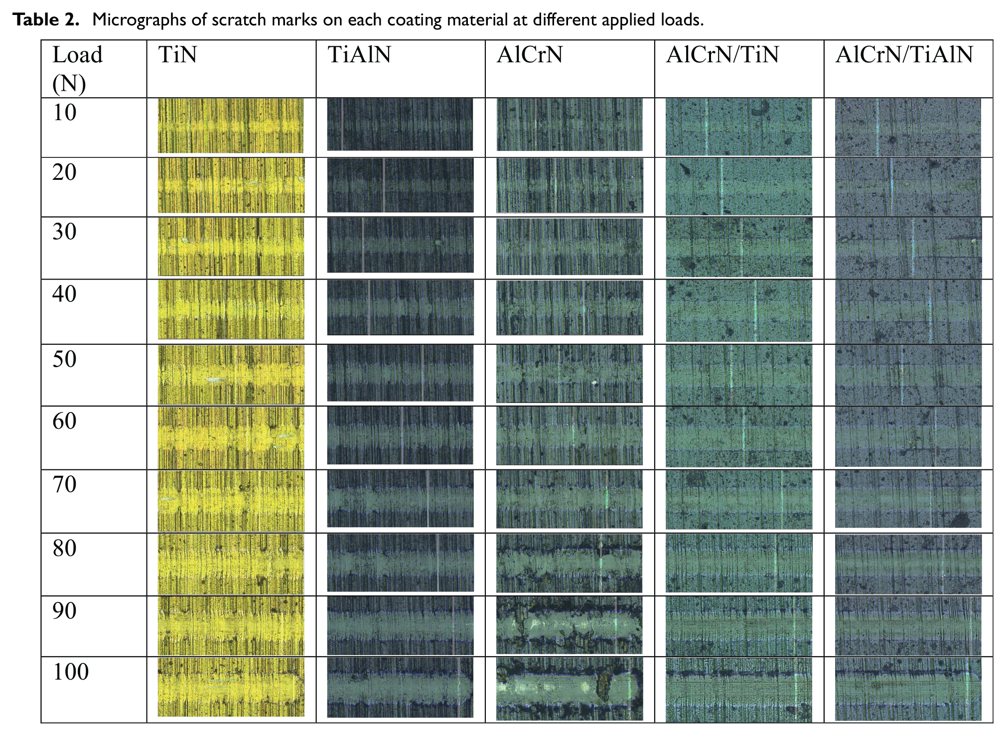
The scratch test was subsequently performed to assess the adhesion of coating layers, and the results are shown in Figure 4(c). Lc1 indicates the force at which the coating starts to be deformed. The scratching force of 16.27 N can introduce the deformation of TiN-coated sample while the others required a higher force to yield the Lc1 criterion. When the applied load was further increased with the scratching distance, cracks were initiated on the coating surface noted by Lc2. The single-layer coating of AlCrN first exhibited cracks under the scratching load of 40.46 N and its delamination (Lc3) started after 59.28 N. The critical load of AlCrN is also found to be lower than TiAlN in the study of Mo et al. 5 This finding corresponded with the microhardness of AlCrN (Figure 4(a)) in which the harder the coating material, the higher the tendency for cracking can be apparent. However, the double-layer coatings demonstrated higher Lc2 and Lc3 values than the single layer of AlCrN. This is anticipated that the base-layer coatings, that is, TiN and TiAlN, could play a significant role in resisting the crack initiation and delamination of coatings. Scratch marks obtained under different applied loads are shown in Table 2, also highlighting the severe damage of AlCrN compared to the others.
Micrographs of scratch marks on each coating material at different applied loads.
Drilling performance of uncoated and coated tools
The uncoated and coated drills were used to make holes in a medium carbon-steel block. Torque and thrust force occurred during the drilling process were measured using a dynamometer. To realize the torque and thrust force without any effects of tool wear, the measurements were taken at the first hole drilling, and their averages were plotted as shown in Figure 5(a) and (b). Based on a number of experiments, the coefficient k denoted in equation (25) was determined using a regression analysis and the value was approximately 0.55. The total torque and thrust force expressed in equations (27) and (28) were then calculated, and the predictive results were found to correspond to the experimental measures with the average error of 8.4%. This is similar to the prediction error reported in the modeling works of Nayebi and Vaghefpour 13 (∼6%) and Naisson et al. 14 (∼10%).
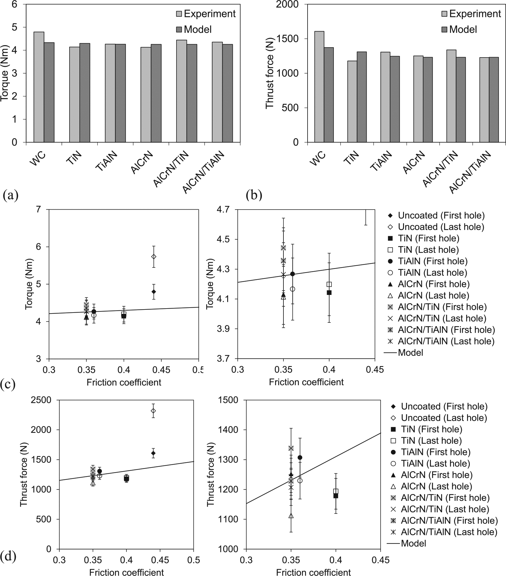
Measured and calculated (a and c) torque and (b and d) thrust force in drilling process.
The highest drilling torque of 4.8 N m and thrust force of 1608 N belonged to the uncoated drill, followed by the double-layer and single-layer coatings of AlCrN, TiAlN and TiN, respectively. The drilling torque was found to range in between 4 and 5 N m for all tested while a remarkable difference between uncoated and coated drills was apparent in the thrust force aspect. The force for uncoated drill was greater than the coated ones by approximately 28%. As the drill geometries and drilling condition were identically the same for all tests, except the drill surface properties, the discrepancy of drilling torque and force was therefore subjected to the sliding mechanics of cut chip and rake face of drills.
The average cutting speed used in this study was 60 m/min. The friction coefficient of uncoated and coated WC surfaces at 60 m/min sliding speed were taken from Claudin et al., 18 where the coefficient between the surfaces of medium carbon steel and WC, TiN, TiAlN and AlCrN is 0.44, 0.4, 0.36 and 0.35, respectively. By plotting the torque and thrust force against the friction coefficient, the experimental results were distributed on the same trend of the predictive models as shown in Figure 5(c) and (d). As per the figure, the increase in drill surface’s friction increases the torque and thrust force obtained. In addition, the drilling torque and thrust force occurred in the last hole drilling were plotted in the figure for the purpose of comparison. In this study, the last hole was the 400th hole for the coated drills while the uncoated drill exhibited tool fracture at the 200th hole; so that this was considered as the last hole for the uncoated drill. By comparing the torque and thrust force introduced by the first and the last drilling tests, the results were not so different when the coated drills were employed. However, the cutting loads were remarkably increased with the number of holes drilled for the uncoated tool. The rapid tool wear and fracture were the main reasons for the changes in drilling torque and thrust force.
Wear on the flank and rake faces of drill lips was examined in this study, and their micrographs are presented in Figure 6. As shown in Figure 6(a), the uncoated drill clearly exhibits fracture along the cutting edges after drilling 200 holes. The low hardness and high friction coefficient of uncoated surface compared with the coated ones substantially introduced the adhesion and abrasion wear on the tool–chip and tool–workpiece contacts during the cutting process. The loss of tool material elements and thermo-mechanical stress developed at the drill lips weakened the cutting edges and then resulted in the tool fracture. By contrast, all coating materials examined in this study can importantly resist the tool wear and fracture of WC drill as shown in Figure 6(b)–(f).
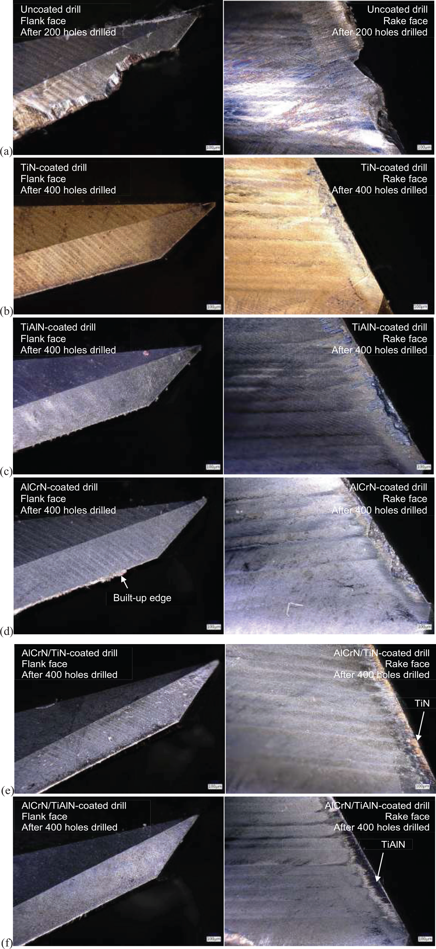
Flank (left) and rake (right) faces of drills: (a) uncoated, (b) TiN coated, (c) TiAlN coated, (d) AlCrN coated, (e) AlCrN/TiN coated and (f) AlCrN/TiAlN coated.
The width of wear land appeared on the flank and rake faces of drill lips was measured and plotted in Figure 7, indicating that the TiAlN-coated drill has the smallest wear among the others. This finding also corresponded to the hardness, and scratch test results that the TiAlN provided relatively high hardness and high damage threshold for Lc1 to Lc3 (Figure 4(c)), hence preventing the coated tool from wear. Although the AlCrN-coated tool can promote better wear and crack resistances than TiAlN as reported in the study of Fox-Rabinovich et al., 4 the wear rate of this coating material was found to be higher than TiN and TiAlN in this study as well as Vettivel et al.’s 19 work. As per Figures 6 and 7, the wear land on rake face was found to be much larger than the flank face. This is anticipated that the large clearance angle of drill lips can minimize the adhesion and abrasion wear at the tool–workpiece contact. All AlCrN-coated samples exhibited severe wear on the tool rake face. For the double-layer coatings, the top coat of AlCrN was drastically worn out, revealing the bottom coats of TiN and TiAlN as can be noticed in Figure 6(e) and (f), respectively. Since the thickness of AlCrN for the single- and double-layer coatings examined in this study were about the same (Figure 3(f)), the breaking of AlCrN layer at the tool–chip contact region was also expectable. The low thermal conductivity of AlCrN may be a reason to raise the cutting temperature at the tool–chip interface 6 and in turn cause the adhesion wear as well as the built-up edge formation as shown in Figure 6(d).
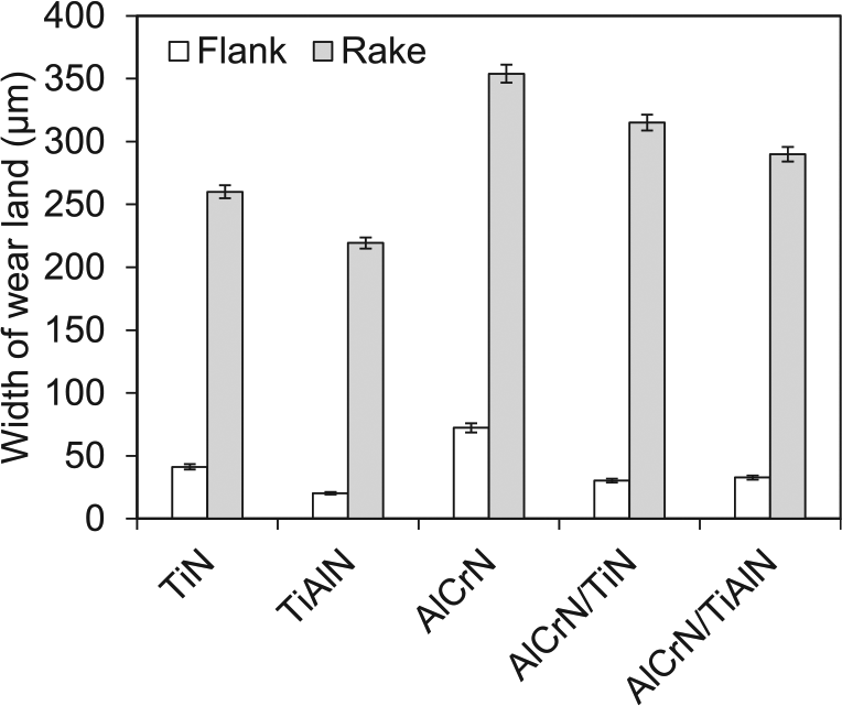
Width of wear land occurred on the flank and rake faces of drills.
The average surface roughness (Ra) of drilled holes was measured every 10 holes, and the results are plotted in Figure 8. The obtained surface roughness was found to significantly increase with the number of holes when the uncoated drill was applied. This corresponds to the tool wear and fracture of drill lips that cause rough drilled surface as a result. However, within the first 60 holes, the uncoated drill introduced the Ra of less than 1.5 μm. This made a better surface quality than that produced by the coated drills whose Ra ranged between 1.5 and 2.5 μm. Since the drill geometries were all exactly the same except the tool surface condition, it can be anticipated that the friction and contact mechanics at the tool–workpiece interface of uncoated drill may substantially induce rubbing action together with the typical shearing mechanism. This can be realized by the high drilling torque and thrust force taking place in the drilling with the uncoated tool. The increase in cutting loads can raise the cutting temperature, thus softening the work material and enabling the smoothened surface of drilled holes. However, this phenomenon cannot last long when the accumulation of cutting temperature becomes significant and adversely expedites the tool wear and built-up edge formation. Regarding the results, the Ra induced by the uncoated drill linearly increased with the number of holes until the 200th hole was reached with the Ra of 2.825 μm, where the significant tool fracture was considered so as the end of tool life.
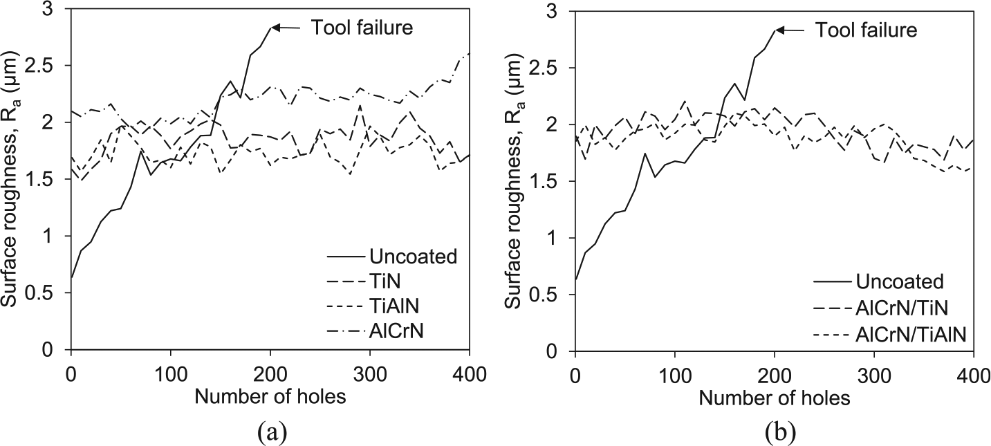
Surface roughness of drilled holes induced by (a) single-layer and (b) multi-layer coated drills.
The coated drills can well maintain the drilled surface quality for at least 400 holes tested in this study, and the TiAlN-coated drill provided the lowest Ra ranging from 1.5 to 2.0 μm. This is due to the high hardness and good adhesion of TiAlN to the WC substrate that retain the tool–workpiece and tool–chip contact conditions throughout the drilling test. By contrast, the AlCrN-coated tool resulted in the poorest surface quality whose Ra linearly increased from 2.1 to 2.6 μm for the first and the 400th hole, respectively. Although the hardness of AlCrN was better than the other coating materials investigated in this study, its poor adhesion property not only led to the rapid wear formation but also produced the rough surface finish.
By considering the double-layer coatings, there was no substantial difference between the two coatings examined. However, it can be noticed from Figure 8(b) that the Ra values are gradually increased and then decreased after drilling 200 holes. Based on the scratch test and tool wear results, it is reasonable to imply that the AlCrN top coat was substantially delaminated or cracked after a certain number of drilling (about 200 holes in this study), and the bottom coat of either TiN or TiAlN later makes a contact with the chip and workpiece surface. This thereby changes the sliding behavior in drilling process so as the obtained surface roughness. Since the friction coefficient of TiN and TiAlN is less than that of AlCrN, low cutting loads, less tool wear and small Ra can be expected accordingly. This could be a reason for the decrease in Ra after drilling 200 holes with the double-layer-coated tools.
Conclusion
The surface characteristics and drilling performance of uncoated and coated WC drills were investigated in this study. The microhardness, average surface roughness and adhesion force of single- and double-layer coatings of TiN, TiAlN and AlCrN were experimentally examined, and their effects on drilling torque and thrust force were compared with the theoretical models. In addition, tool wear and hole surface roughness obtained were reported and discussed. The findings of this research can be concluded as follows:
Although AlCrN provided the highest microhardness among the other coating materials, its adhesion property and wear resistance were found to be very poor. The significant crack and fracture of AlCrN coating was more noticeable than the others in the scratch test results.
The drilling torque and thrust force were high when the uncoated tool was applied while the TiN-coated drill provided the lowest cutting loads. The predicted torque and thrust force obtained from the theoretical model showed a good agreement with the experiments with the average error of 8.4%. In addition, the modeling work presented in this article could enable a better understanding of drilling mechanics for advancing drill geometry and its coating onward.
TiAlN-coated drill had the smallest wear on the rake and flank faces of drill lips, followed by TiN and AlCrN samples. The substantial built-up edge was found at the cutting edge of AlCrN-coated drill. The poor thermal conductivity of AlCrN could be a reason for the built-up edge formation and adhesion wear.
The double-layer-coated drills whose top coat was AlCrN did not importantly reduce the cutting loads. Regarding the poor adhesion and brittleness of AlCrN coating, the advantage of using AlCrN as the top coat was not discernible in this study.
The smoothest cut surface was produced using the TiAlN-coated drill, and the average surface roughness ranged from 1.5 to 2.0 μm throughout the 400 hole drillings.
According to all findings, the TiAlN-coated drill was recommended, as it can result in low cut surface roughness and less tool wear.
Footnotes
Declaration of conflicting interests
The author(s) declared no potential conflicts of interest with respect to the research, authorship and/or publication of this article.
Funding
The author(s) disclosed receipt of the following financial support for the research, authorship, and/or publication of this article: This research was financially supported by the Department of Production Engineering, Faculty of Engineering, King Mongkut’s University of Technology Thonburi under the graduate student research grant.