
Abstract
This article reports a systematic study which examines the use of solid lubricants in the sequential deposition and machining of wire and arc additive manufactured parts and characterises the effects of solid lubricants on the microstructure. This article also describes the microstructure developed and the effect on microhardness by manual cleaning of deposited layers with acetone. Mild steel wire consumable electrode G3Si1 with the diameter of 0.8 mm was used. The use of graphite and molybdenum disulphide as solid lubricants in machining was also studied and a scanning electron microscope was used in detecting any form of lubricant contamination. A systematic study shows that a significant amount of solid lubricant contamination can be found in the deposited material. Furthermore, the results indicate that even cleaning of the wire and arc additive manufactured surfaces with acetone prior to the weld deposition can affect the microstructure of the deposited material.
Introduction
Wire and arc additive manufacturing
Additive manufacturing (AM) can be regarded as a concept for direct production of components in a range of materials such as steel, aluminium, plastic and titanium. AM has the ability to manufacture very complicated three-dimensional (3D) physical geometries devoid of geometric restrictions. 1 AM can be classified into selective laser sintering (SLS) also known as powder-based additive manufacturing (PBAM) and wire and arc additive manufacturing (WAAM), which is wire-based AM. 2 WAAM is an aspect of AM in which metallic components are manufactured by welding beads in a layer-by-layer manner. The wire-based technique aims at overcoming the issues of powder-based solution. WAAM deposition rates can be very high and having virtually no restriction concerning the size of the part to be manufactured. 2 The demand for WAAM has been on the increase over the past years. A study in the Wohler’s report 2010 3 reported that the request for products and services from WAAM technology has been robust for more than 20 years. This is because of its flexibility as this procedure allows the manufacture of large custom-built metal workpiece with high-quality welds. 3 This technology can help to realise large savings in the form of reduction in metal waste, reduced lead-time and elimination of tooling cost. 3 The total avoidance of tooling in WAAM techniques gives design freedom and the design process can be more flexible. 4
Nevertheless, the surface of WAAM parts has a significant surface roughness in contrast to general numerical control (NC) machined parts owing to the WAAM process itself. 1 Researches2,3,5,6 have investigated the various aspects of manufacturing using AM, but little research has been done on the machining aspect of it. As part of the study on machining of AM, Yang et al. 1 concluded that owing to the dynamic effect, layer-based machining (LBM) could be better used in large objects devoid of thin walls.
However, various WAAM parts of intricate sizes have been produced with less concern for machining especially when the surface finish is paramount to the requirements.1,7 Moreover, the main benefit of manufacturing a part by WAAM is that the geometric complexity of the part has a considerably smaller effect on the manufacturing method than the traditional material removal processes, and machining of WAAM parts is a lot less wasteful. 3
Sequential WAAM
Recently, LBM has emerged as a promising way of integrating additive and subtractive shaping theories. Since both WAAM and material removal (MR) have their own respective strengths and weaknesses, it is a good idea to realise the benefits of the two processes in an integrated system. This could allow making WAAM geometries with improved accuracy and surface finish with less necessity for complex set-ups of the features. If the time required to deposit a layer is presumed to be dependent on the layer thickness, and the speed of machining is assumed greater than the speed of the deposition process, then the overall speed of the combined WAAM and MR is faster than the WAAM process alone.1,7
Although machining of WAAM walls has its unique features, it has some inherent problems using computer numerical control (CNC) machining methods. The most obvious issue is that models with hollow features or very deep cavities can be impossible to be machined. 1 However, in an earlier study 1 of where WAAM and machining were not performed on the same machine, after deposition of this part with a hollow shape, the material was cut to allow the hollow parts to be machined and after machining, the parts were glued together with the aid of an adhesive. The method presented in this article does not involve the use of any adhesive as this involves the sequential WAAM deposition and machining on the same system.
The process analysed in this article involves carrying out both welding and machining sequentially on a single integrated system and integrates both material deposition with material removal to arrive at the necessary surface finish. The novel integrated method can decrease the total time for the deposition and improve shape accuracy.5,8
Solid lubricants
Cutting fluids help to lubricate the machining zone, thus reducing the friction between the machining tool and the workpiece and reducing the amount of frictional heat being generated. It can also help to cool the machining zone by extracting some of the generated heat. However, cutting fluids also come with disadvantages, which include cost, significant potential health and safety risks and government legislations. 9 These disadvantages forced companies to reduce the toxicity of all wastes including cutting fluids being returned to the environment and to increase the biodegradability of their waste products. 10 In addition, the cutting fluids earn a significant portion of total manufacturing cost. 9 Consequently, there is a real need to either eliminate or significantly reduce the use of cutting fluid. As an alternative to cutting fluids, solid lubricants such as graphite and molybdenum disulphide (MoS2) are being currently used in machining. It does not have any pathogenic history and hence do not pose any significant health hazard to workers. 11 They are readily available and biodegradable. Due to the numerous advantages offered in terms of machining performance and ecological machining, solid lubricants are becoming increasingly popular as an alternative to conventional cutting fluid. 11 In this context, there is a clear interest to explore the potential for using dry and solid lubricants within abrasive machining for WAAM, developing upon the existing minimum quantity lubrication (MQL) theories in order to establish a stable and reliable machining process.
This study aims at understanding the possibility of sequential deposition and machining using solid lubricants since it is difficult to manufacture WAAM parts and machine them in an environment of lubricating liquids due to hazard of electric shocks. This article highlights the effects of using solid lubricants in machining of additive manufactured structures on surface integrity and material properties.
Materials and machine set-up
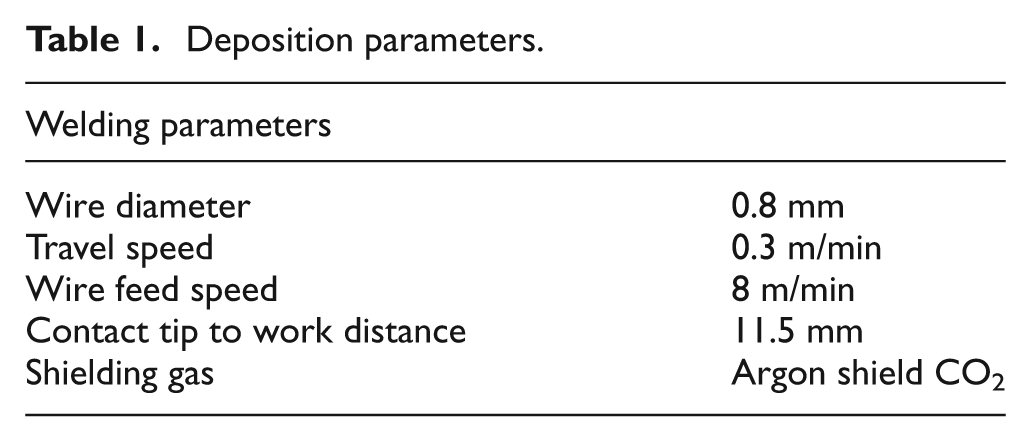
This study was conducted using the pre-set operating parameters shown in Table 1. The material used is mild steel coming as a consumable electrode G3Si1. The wire has excellent feedability and very consistent welding performance with little spatter. A Fronius Trans Pulse Synergic 5000 Cold Metal Transfer (CMT) welding machine was used for the deposition process. Details of the equipment are shown in Figure 1 with an ABB IRB 2400 robot coupled to the CMT machine for the motion of the arc.
Deposition parameters.
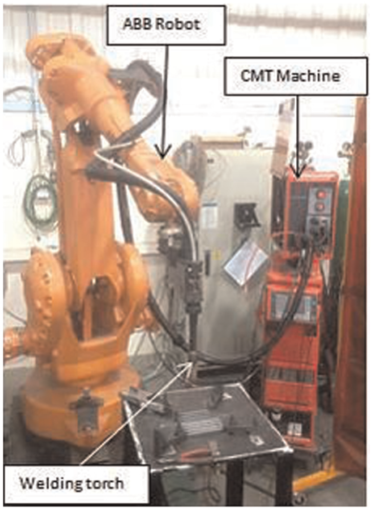
Experiment set-up.
Methodology
Graphite powder and molybdenum disulphide powder were used in the trials due to their wide usage, the ability to maintain their properties as lubricants and the stability at high temperature. 12 Widely used conventional oil-based machining fluid (EcoCool machining fluid) 11 was used for the comparison with the solid lubricants.
A systematic experimental approach was used (see Table 2). Stage 1 involves sequential deposition of walls with or without the application of lubricants. This is without any form of cleaning operation performed on the walls before or after each layer of deposition. Stage 2 involves the sequential deposition of walls with and without the application of solid lubricants as in Stage 1, however, with cleaning of the lubricant after each layer of deposition. The cleaning operation involves thorough manual cleaning of the top surface of the deposited WAAM beads with the use of cotton wool and 99% acetone. This is important because of the necessity to remove the traces of solid lubricant during and after the machining operation to avoid any contamination of the material surfaces.
Trial procedures.
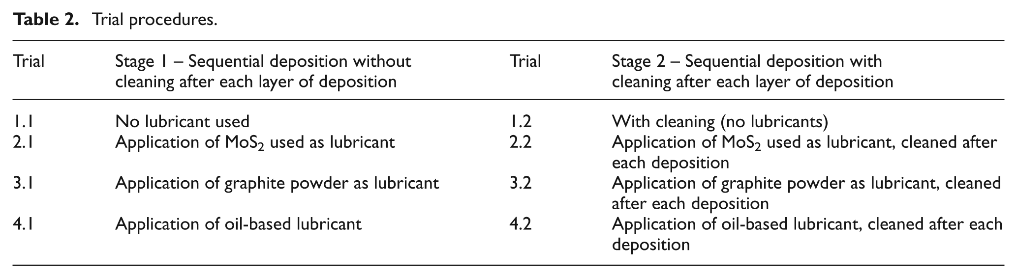
Trial 1 in Stage 1 consists of wall build up without cleaning after each layer of deposition, while Stage 2 of Trial 1 consists of wall build up with cleaning after each layer of deposition. Trial 1 is the only trial that does not involve any form of lubricants, either solid or fluid. This experiment serves as the control in which no lubricant was applied. Apart from this Trial 1, all other trials (Trials 2, 3 and 4) use either a solid lubricant or a fluid lubricant as shown in Table 2. Trial 2 involves the application of MoS2 on the surface of every single layer deposited and in Stage 2 of this trial. In Trial 3, graphite powder was applied instead of MoS2 as in Trial 2, and Trial 4 involves the application of machining fluid. Each time, 4 mL of solid lubricants was applied over a deposited single bead of 80 mm. For all the trials, the materials were allowed to cool down to room temperature.
The layout of the base plate and the deposited walls are shown in Figure 2. After the deposition, the walls were sectioned (section A–A in Figure 3) to show the microstructure of the samples. The subsurface layer preparation was done before imaging the microstructure of the material. This process involves setting the samples on the resin and allowing to cure. Other microstructural preparation includes grinding using different grades of abrasive grinding paper, a 6-µm-diamond paste for polishing and then etched with 2% Nital solution for 20 s. This exposes the grain structure to identify the microstructure. Figure 3 shows the region of the application of lubricants. The region is the point of the application of lubricants as well as the layer of interface between each layer of deposition. The microstructures were taken at the interface of the weld (section A–A in Figure 3), which is also the area of the application of the lubricants.
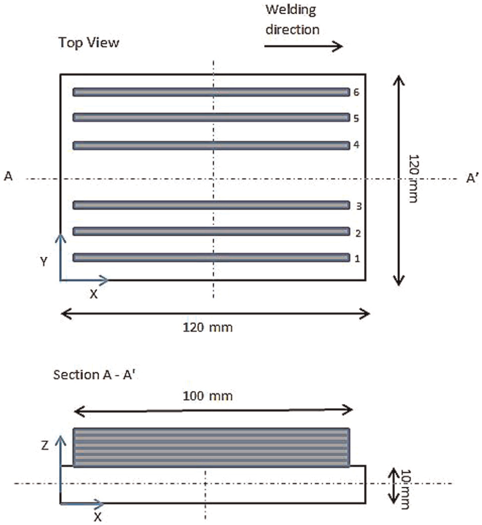
Illustration of the base plate with the wall build up.
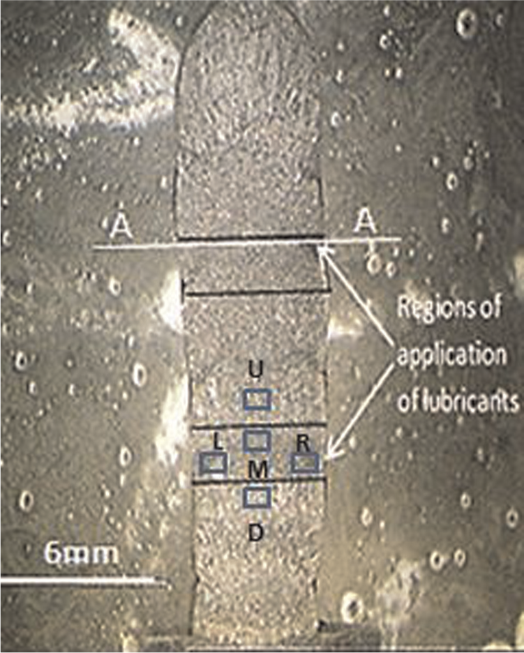
Regions of the application of lubricants.
The microhardness of the structures was examined on a Zwick micro Vickers hardness testing machine using a load of 200 g, which was applied for a duration of 20 s. The microhardness test was conducted three times and measurements were taken across the weld interface at points upper (U), down (D), left (L), middle (M) and right (R) (see Figure 3). For this study, a XL 30 scanning electron microscope (SEM) was also employed for detecting any form of lubricants embedded in the material. The samples were scanned and analysed using the image processing software INCA®. As this research focuses on the effect of lubricants on WAAM parts only, the actual machining process has been deliberately omitted. This work provides the fundamental knowledge for the succeeding machining process of AM structures with lubricants.
Results and discussion
Microstructure
Figure 4 illustrates the microstructure of the deposited materials at various stages of the trials. Figure 4(a) shows the microstructure at the weld interface when no form of lubricant was applied (Trial 1.1). It shows that the structure is composed of columnar proeutectoid ferrite and fine acicular pearlites intermix with a small quantity of fine acicular pearlite between the columnar dendrites. Figure 4(b) shows the microstructure obtained when the sample was cleaned with acetone prior to each layer deposition (Trial 2.1). The micrograph shows an anequiaxed grain and mainly consisted of massive ferrite with big grain structure. This could be attributed to the cleaning of the deposited surfaces. The microstructure of the sample during sequential deposition with MoS2 as lubricants is shown in Figure 4(c) and (d) (Trial 2.1 and 2.2). Figure 4(c) illustrates the microstructure of the sample when the sample weld bead was not cleaned after each layer of deposition but MoS2 used as lubricant. The microstructure here is predominantly bainite with islands of ferrite. It is known that the rate of the formation of bainite in the process of the intermediate transformation is determined by the rate of removal of carbon from the front of the growing crystallite due to the diffusion redistribution and by the number of emerging crystallisation centres. 13 The carbon redistribution during this process was affected by the inclusion of MoS2 which was used as lubricant and thus finds its way into the molten metal during the WAAM deposition. This addition of MoS2 promotes the formation of bainite structure.
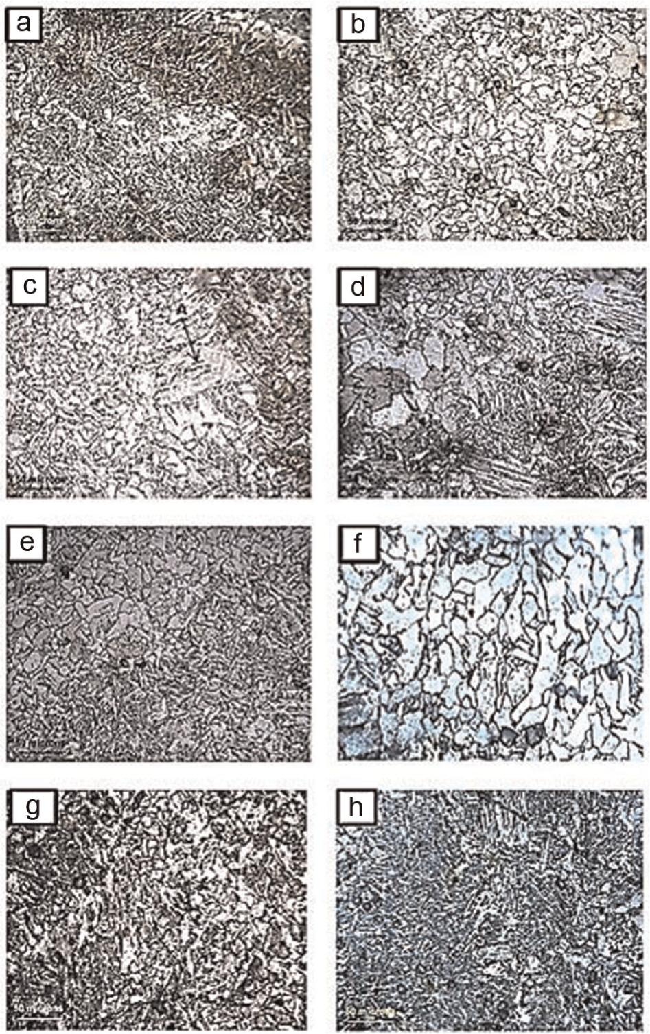
Cross-section of the microstructure of the sample during deposition: (a) Trial 1.1, (b) Trial 1.2, (c) Trial 2.1, (d) Trial 2.2, (e) Trial 3.1, (f) Trial 3.2, (g) Trial 4.1 and (h) Trial 4.2.
There are some patches of large ferrite grains, which can be attributed to the contamination of the weld surface by MoS2. However, Figure 4(d), which is Trial 2.2, shows the microstructure with cleaning of the surface of the deposited layer after the application of MoS2. The microstructure comprises mixed coarse grains and some amount of long-grained ferrite. Some large grain structure is also noticed in this sample. Figure 4(e) and (f) (Trials 3.1 and 3.2) shows the microstructure of the samples when graphite was used as the lubricant. Graphite being an allotrope of carbon can combine easily with the molten mild steel materials used in this trial. However, in Figure 4(e) which is the microstructure of the sample during sequential deposition with graphite as lubricant, the graphite remains on the surface of the weld bead without cleaning. The microstructure here is characterised by the presence of ferrite with aligned and non-aligned second phases, grain boundary ferrite and a ferrite/carbide aggregate that appears to be fine pearlite. The fine pearlite is as a result of the mixture of carbon with the weld pool during deposition. Moreover, when the graphite was cleaned, the microstructure (see Figure 4(f)) exhibits equated ferrite grains and larger grains of fine pearlite and the weld has been re-austenite by subsequent weld deposit. This has the effect of refining the grain structures by eliminating the columnar grains and replacing them with relative fine polygonal ferrite surrounded by acicular ferrite.
With the sequential deposition of layers with oil-based lubricant without cleaning after each deposition (see Figure 4(g), Trial 4.1), the structure shows a pearlite which reduces the hardness but tend to increase the ductility of the material. It also shows areas of a mixture of ferrite and pearlite grains. When the fluid lubricant was cleaned (see Figure 4(h), Trial 4.2), the microstructure exhibits fine grains of acicular ferrite formation with some areas of coarse pearlite.
This investigation has shown the effects of using acetone to clean WAAM samples on the microstructure. Without the application of lubricants, the grain size of the microstructure tends to become larger when cleaned with acetone. When a lubricant was applied, there are areas of large grain sizes. The big grain size appears in all the microstructures that were cleaned with acetone and this can be attributed to the reaction of acetone with the weld samples. Although acetone was allowed to dry before depositing the next layer, it caused an increase in the grain size of the sample. The areas of large grain sizes exhibited in Figure 4(d) and (f) resulted because of cleaning with acetone. Conclusively, dry machining might be the only possible way of manufacturing WAAM parts when applying sequential deposition and machining if no contamination is allowed.
Microhardness of the weld
Figure 5 shows the comparative hardness profile of the samples. One can see through the solidification of the deposited weld zone that the parent material commonly lost its unique strength induced through strain hardening. 1 Generally, in the event of carbon and low alloy steel, development of bainite or martensitic stages in the deposited weld region encourages an upsurge of hardness. The macrohardness chart shown in Figure 5(a) showed the hardness of the deposited material with and without cleaning when no lubricant was applied in the interface of the layer. It has an average hardness of 219 VH and the microhardness outside the deposited layer interface has an average of 258 VH when no cleaning took place. With the cleaning, the average hardness at the interface of the layers decreased to 200 VH and the microhardness outside the deposited interface was 250 VH. However, Figure 5(b) shows the microhardness profile with the application of MoS2 as a lubricant. In this case, MoS2 was applied to the interface of the layers deposited and subsequent layers deposited without cleaning as shown in Trial 2, Stage 1 and with cleaning as shown in Trial 2, Stage 2. The average microhardness without cleaning at the weld interface is 213 VH, and for the microhardness taken outside the weld interface, this has an average of 244 VH. After the cleaning operation, the average microhardness at the interface decreases to 196 VH, and outside the region of the interface, the average microhardness is 242 VH. Furthermore, when the same process was repeated with the use of graphite as a lubricant, Figure 5(c) shows the outcome of the results of the microhardness with the average microhardness of 212 VH when the graphite was used without cleaning and outside the weld interface has an average microhardness of 243 VH. However, when the graphite was cleaned, the average microhardness at the weld interface also decreased to 190 VH, and outside this region, an average of 249 VH was attained. Figure 5(d) shows the microhardness profile with the use of oil-based lubricant to the interface. This is with no cleaning; the average microhardness for the material is 202 VH as compared to the region outside the weld interface with an average microhardness of 243 VH.
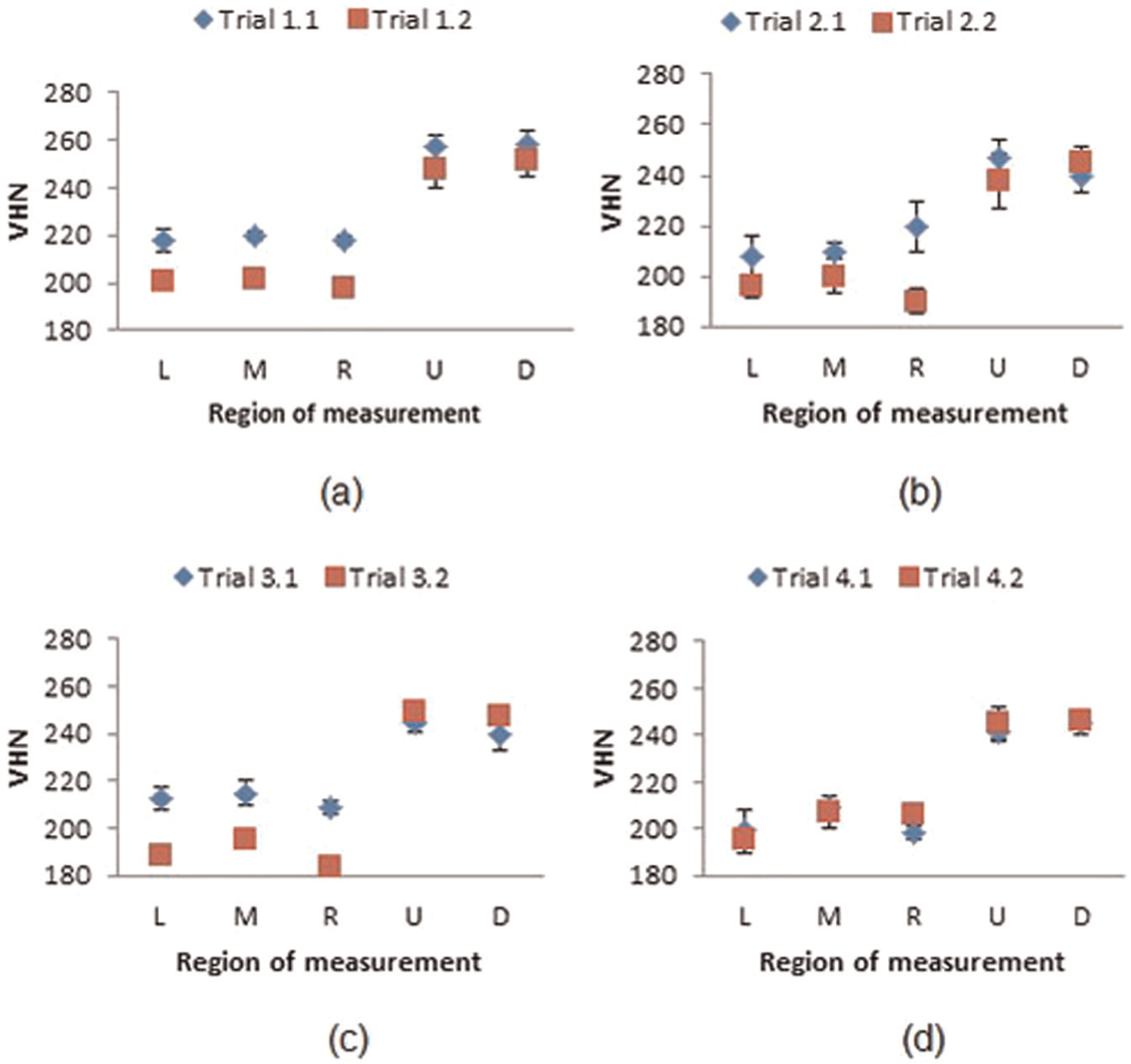
Effects of the application of lubricants of the microhardness: (a) no lubricant, (b) MoS2 as lubricant, (c) graphite as lubricant and (d) MQL.
With cleaning off this lubricant with acetone and allowing it to dry off, the micro-hardness remains virtually at the same region with no cleaning operation. It has an average microhardness of 203 VH, and outside the weld region it has an average of 245 VH.
Hardness is a critical property of engineering materials. It is a function of the microstructural grain structure. 14 The hardness property of the samples where no form of lubricant is applied recorded the highest Vickers hardness. However, there is a reduction in the Vickers hardness value when cleaning was applied due to the increase in the grain size. However, with the application of both graphite and molybdenum disulphide on the sample, there is also a reduction in the Vickers hardness and this can be attributed to the effects of contamination through the application of the solid lubricants. Moreover, with the application of oil-based lubricant, the variation in the Vickers hardness is not significant between the samples with cleaning and samples without cleaning. This can be attributed to the oil-based lubricant having no significant effect on the microstructure and the mechanical properties.
Generally, it was found that in the welding zone where no lubricant was applied, a higher microhardness can be observed than when cleaning took place. Also, the microhardness outside the weld deposition zone at the surroundings has a significant higher microhardness value. These phenomena occur as a result of the grain size; a previous study by Liu et al. 14 indicated that in general, the Hall–Petch type of linear relationship was followed between microhardness and the grain size.

where HV is the microhardness, d is the grain size and a and b are the parameters related to phases in materials and in one weld, they are constant. It can be seen that the smaller the grain size, the higher the degrees of microhardness. The grain boundaries become the main obstacle to the slip of dislocations, and the zone with a smaller grain size would have higher microhardness as more grain boundaries would impose more restriction to the dislocation movement.
Temperature effect around the welding region
In order to be mindful with the temperature around the welding zone during deposition, a 3D transient thermal model was used. The software used is Abaqus 6.9−3. The model covers the heat generation by the welding arc as well as the heat conduction in the deposited components. Heat losses through the free surfaces and through the cooling system under the base plate were included in the model. The welding arc was simulated as a volumetric heat source with a power density moving along with the torch. The Goldak double ellipsoidal heat source 15 was used to apply the heat to the WAAM deposits. The power density of the region in front of the arc centre and the region behind the arc centre was defined separately. 16
To simulate the material deposition process, the filler material was simulated using the ‘element birth technique’. 17 With the model change option in Abaqus, all the elements of the deposited wall were deactivated at the initial step of the analysis, and then sections of elements were activated in successive steps to simulate the metal deposition as the weld torch travels along the base plate.
The plot of the simulation (see Figure 6) shows the temperature of the weld pool. This helps to understand what might have happened to the lubricants during and after WAAM deposition. The plot shows the temperature of the weld pool during deposition to be almost 2800 °C and every other region around the welding pool lies between 1500 °C and 30 °C. A review on the study of the melting point of graphite between 1963 and 2003 shows that graphite melts at 4527 °C ± 200 °C. 18
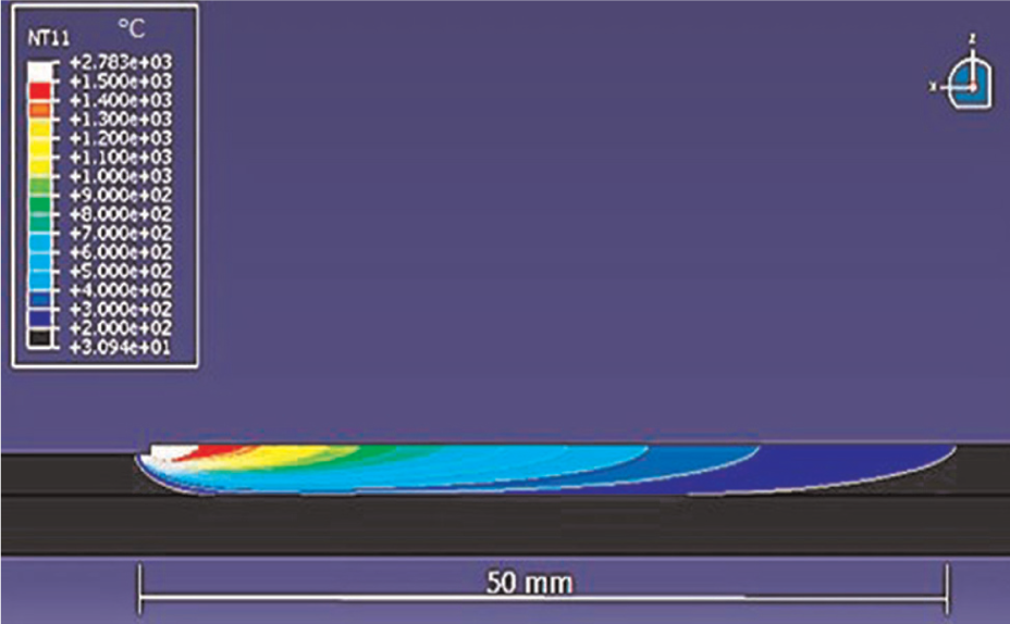
Temperature plot during the welding operation (all in °C).
With these data, the graphite used in the trial will not melt or sublime since this is above the highest temperature of the welding pool. Moreover, the graphite might have mixed with the molten material during the welding deposition. Contrary to the high melting point of graphite, MoS2 has a much lower melting point of 1185 °C. MoS2 sublimes above this melting point and they are moderately unreactive chemically unless physical and mechanically activated. 19 At the temperature above 700 °C, MoS2 may react with steel at the weld pool

The molybdenum that resulted from this reaction can diffuse into the weld pool. Moreover, at room temperature, chemical reactions could be expected and in fact sometimes noticed between disulphide, metal surfaces and mist air. 19
SEM analysis
The percentage of lubricants at the interface between the deposited weld, that is, the point of the application of the lubricants, was analysed. In the analysis, SEM was used to the study the chemical compositions (see Figures 7 and 8). The analysis indicates the elements present in the scanned area. Table 3 lists the elemental composition of the samples. The analysis shows the presence of carbon (C), potassium (K), aluminium (Al) and oxygen (O). Other elements present include magnesium (Mn) and iron (Fe). Figure 7 shows the elements present in the (Trial 1−1) sample with sequential deposition of wall without cleaning after each deposition when no lubricant was applied. This figure shows the presence of potassium (K), aluminium (Al) and oxygen (O) in Trial 1−1. Figure 8 shows the results for Trial 1−2. One can see that the elements from Trial 1−1, which includes potassium, aluminium and oxygen, are absent in Trial 1−2. This indicates that cleaning with acetone could affect the material elemental composition by reaction with the weld surface.
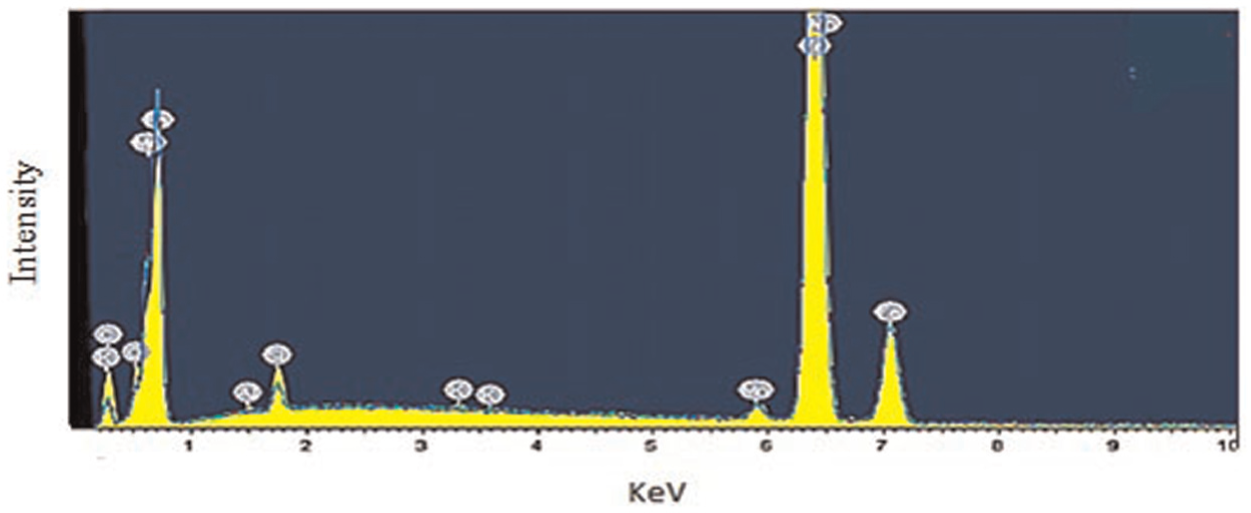
SEM analysis for sequential deposition of wall without cleaning after each deposition with no lubricant.
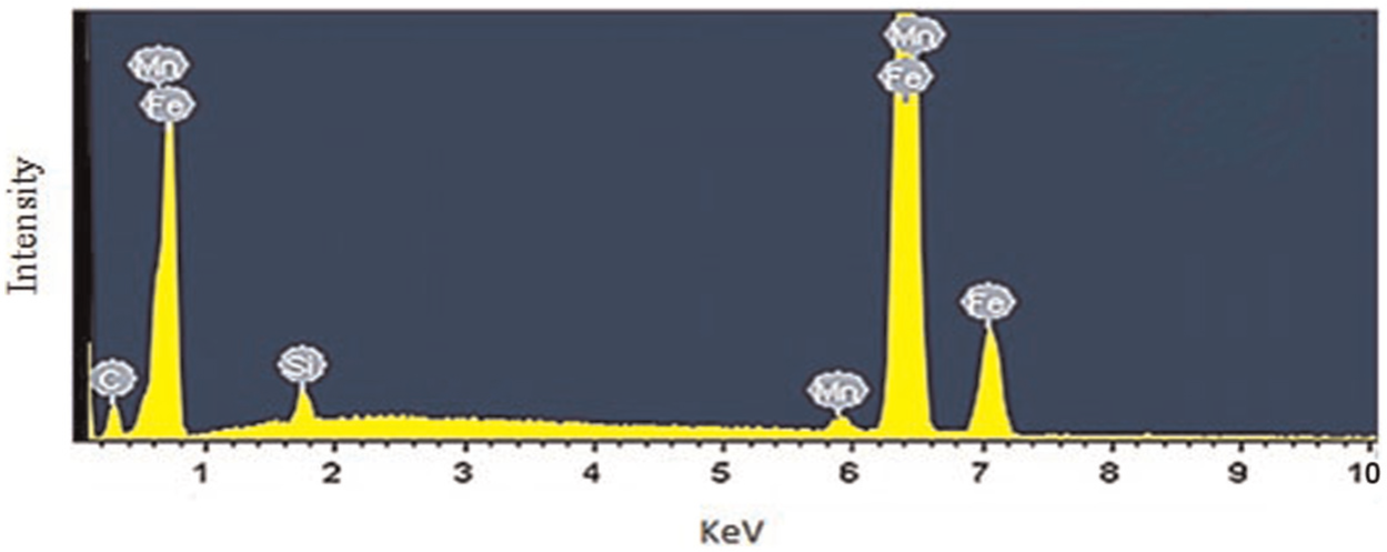
SEM analysis for sequential deposition of wall with cleaning after each deposition (no lubricants).
Elemental composition of the samples by weight.
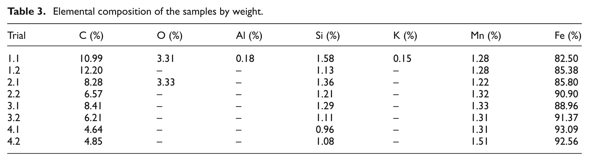
In Trials 1−1 and 1−2, the percentage of carbon present is at a high level when compared with other trials (see Table 3). Trial 1−1 has a carbon content of 10.99% by weight and Trial 1−2 has an elemental content of carbon to be 12.20% by weight. Moreover, Figure 7 shows the elements present in the sample with sequential deposition of wall with cleaning after each deposition. The rest of the results from this trial–apart from Trials 1−1 and 2−1 that show the presence of oxygen–follow the same pattern as shown in Figure 8. Other elements might be present in the analysis but could be insignificant.
Conclusion
The outcomes of this work provide an insight into the use of solid lubricants in sequential machining and deposition of WAAM structures. It also provides beneficial information of using sequential machining and deposition in machining of WAAM structures with hollow shapes. From the above work, the following conclusions were drawn:
The effects of using solid lubricant during sequential machining and its effects on the mechanical properties were analysed with the result that the microstructure of samples can get contaminated with the introduction of solid lubricant and that the chemical composition can be altered.
Cleaning of deposited wall samples with acetone during welding was found to have an effect on the microstructure and hardness during sequential deposition of samples. There is an increase in the grain size of the microstructure when cleaned, resulting in a reduction in the material hardness.
The finite element model (FEM) temperature modelling of the welding pool shows that solid lubricants could have reacted with molten metal during sequential deposition and machining. Knowing the temperature distribution and the melting point of the lubricants is important for selecting the appropriate solid lubricant.
SEM analysis was used to determine the presence of traces of foreign elements in the samples due to the cleaning of the samples. The SEM analysis shows the existence of contaminating elements in the parent material but absence after the cleaning of the sample.
Footnotes
Declaration of conflicting interests
The authors declare that there is no conflict of interest.
Funding
This study was supported by Education Trust Fund (ETF) in Nigeria.