
Abstract
This article presents the development of two-dimensional and three-dimensional finite element–based turning models, for better prediction of chip morphology and machined surface topology. Capabilities of a commercial finite element code Abaqus®/Explicit have been exploited to perform coupled temperature–displacement simulations of an aerospace grade aluminum alloy A2024-T351 machining. The findings show that two-dimensional cutting models predict chip morphologies and machined surface textures on a plane section (with unit thickness) passing through the center of workpiece width, and not at the edges. The contribution highlights the importance of three-dimensional machining models for a close corroboration of experimental and numerical results. Three-dimensional cutting simulations show that a small percentage of material volume flows toward workpiece edges (out of plane deformation), augmenting the contact pressures at the edges of tool rake face–workpiece interface. This enhances the burr formation process. Computational results concerning chip morphologies and cutting forces were found in good correlation with experimental ones. In the final part of the article, numerical simulation results with a modified version of a particular turning tool have been discussed. It has been found that the proposed geometry of the tool is helpful in reducing burr formation as well as cutting force amplitude during initial contact of cutting tool with the workpiece material.
Keywords
Introduction
Since the recent global economic crisis, machining numerical modeling techniques, especially finite element modeling (FEM), have been more encouraged than ever before to increase the machining efficiency, either by suitable selection of cutting parameters or by optimizing cutting tools at their design stage, etc. Altogether, after the advent of super computers with high computational efficiency and improvement in numerical methods, the demand of industrial engineers from researchers to develop qualitative cutting models, replicating actual machining process has increased.
A handful of data of worthy scientific research on various aspects of multiphysical phenomenon of cutting to optimize the machining efficiency is now available. This includes discussion from modeling of machine tool dynamic characteristics for better surface finish,1,2 modeling of burr formation mechanism and its control,3,4 dry and lubricated contacts and frictional modeling at tool–workpiece interface,5–8 models for optimization of cutting parameters,9–11 to cutting tool design and wear prediction models,12–15 and so on.
Keeping in view the complex nature of the cutting phenomena occurring at tool–workpiece interaction level, intricate tool geometry, and computational limitations, most of the contributions are based on simplified two-dimensional (2D) models and techniques.16–19 These models can efficiently predict the physics of the processes occurring in the vicinity of tool–workpiece interface. Nevertheless, these models have their limitations to predict some essential information of the real machining process, for example, cutting forces and machined surface topology for oblique cutting operation, burr formation process, and so on. Three-dimensional (3D) modeling in these particular cases and for some unique machining applications, for example, drilling, is inevitable. Literature review based on 3D models highlighting various aspects of machining can now be found.20–23
In this work, FE-based 2D and 3D orthogonal machining models have been developed aiming at increasing the comprehension of cutting phenomenon and eventually to improve the machining efficiency. Numerical simulations have been performed for turning operation of an aerospace grade aluminum alloy A2024-T351. Limitations of 2D models in precise prediction of chip morphologies and machined surface topologies have been discussed. A workpiece nodes displacement-based scheme 22 has been employed for prediction of burr formation using the 3D cutting model. Experimental results concerning chip morphologies and cutting forces for various machining parameters have been compared with the simulation results.
In the last section of the article, the geometry of the tuning tool used in the present work (Sandvik uncoated carbide insert: CCGX 12 04 08-AL H10) has been tailored to reduce the burr formation.
Experimentation and results of orthogonal turning operation
To perform orthogonal cutting of A2024-T351, the cutting edge of the turning tool (CCGX 12 04 08-AL H10) with 0° edge inclination angle and 90° edge entering angle was orthogonal to feed and cutting speed, simultaneously. Cutting tool mounted on the dynamometer platform (Kistler 9257B) is shown in Figure 1.
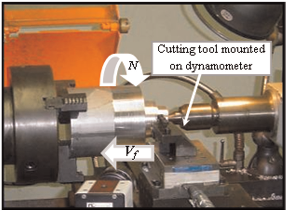
Experimental setup for orthogonal turning operation.
Dry turning operations were carried out considering the following cutting parameters: f = 0.3 and 0.5 mm/rev, aP = 4 mm, VC = 800 m/min. Cutting forces were registered for a subsequent data manipulation. Chips were photographed after necessary etching and polishing treatments (Figure 2). Substantial detail on the experimental approach is elaborated in a previous work of the authors. 19
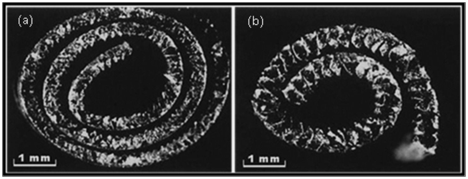
Experimental chip morphologies for Vc = 800 m/min, ap = 4 mm: (a) continuous chip for f = 0.3 mm/rev and (b) segmented chip for f = 0.5 mm/rev.
2D and 3D FE models for orthogonal turning operation
Geometrical configurations, boundary conditions, and interactions
2D and 3D FEM for A2024-T351 turning was realized in a commercially available FE code Abaqus®/Explicit. Figure 3 shows the conceived geometrical model for 3D orthogonal machining.
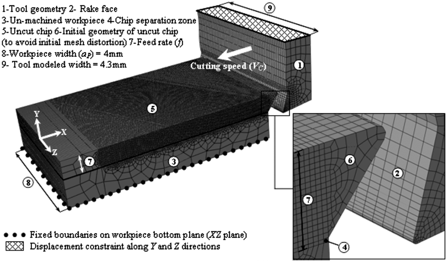
Three-dimensional geometrical model and boundary conditions for orthogonal turning.
Numerical cutting models based on Lagrangian formulation result in severe mesh distortions, in vicinity of the tool–workpiece interface under dynamic contact conditions. To improve the contact conditions and to reduce the mesh distortion, workpiece was modeled in three parts in the present work: uncut chip, chip separation zone, and un-machined workpiece. These parts were assembled with tie-constraint (Abaqus integrated algorithm), to make a single unit “workpiece.” Geometrical profile of the cutting tool was similar to that used in the experimentation. Fixed boundary conditions were assumed on workpiece bottom plane, whereas tool displacement along Y and Z directions was restricted. To perform coupled temperature–displacement calculations, various mesh densities of thermally coupled continuum brick elements C3D8RT were used in different sections of tool and workpiece.
On account of comparison of 2D and 3D model results (later in section “Simulation results and discussion”), 2D model was developed similar to 3D model. Workpiece and tool were meshed with thermally coupled quadrilateral continuum elements CPE4RT, with plane strain hypothesis.9,10,19 Mesh sizes in various sections of tool and workpiece were similar to those conceived in 3D model. In resemblance with the 3D model, workpiece movement in 2D model was constrained with fixed boundary conditions, while tool could move only along negative X-axis (cutting direction).
During machining, tool interacts with the workpiece and chip makes self contact. These interactions highly influence the physics of the ongoing cutting process and need careful frictional contact modeling to reproduce actual machining results. In this context, the most commonly used Zorev’s stick–slip contact friction model 24 with an average friction coefficient µ = 0.17 23 has been incorporated in the present numerical cutting models.
Material behavior formulations
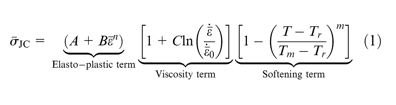
Material constitutive model to realize chip formation and separation during cutting simulations was based on coupling between material damage and its fracture energy. Complete details on the development of this model have been explained in the authors’ recent work. 19 However, the important formulae of this model are herein summarized.
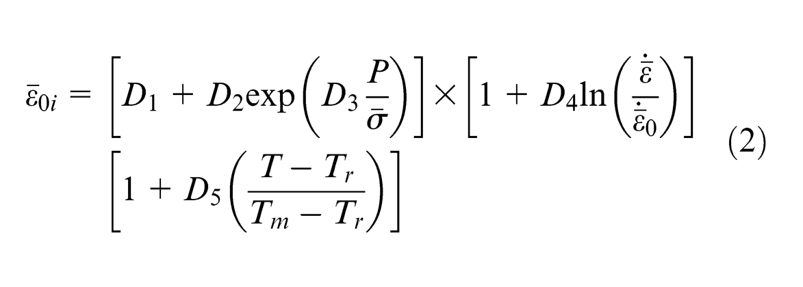
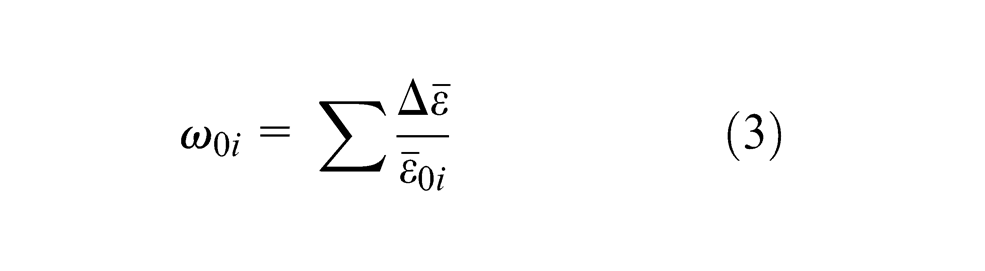
To calculate equivalent stresses, Johnson and Cook (JC) model (1) has been employed. Formulations for material damage has been defined in two steps: damage initiation (JC shear failure model (2)) and damage evolution. Damage is assumed to be initiated in an element when scalar damage parameter
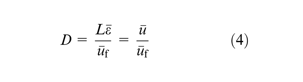
whereas a scalar stiffness degradation parameter D is used to define damage evolution.
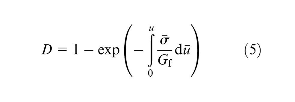
This latter parameter evolves linearly (equation (4), used for chip separation zone part of the workpiece) or exponentially (equation (5), used for uncut chip part of the workpiece)
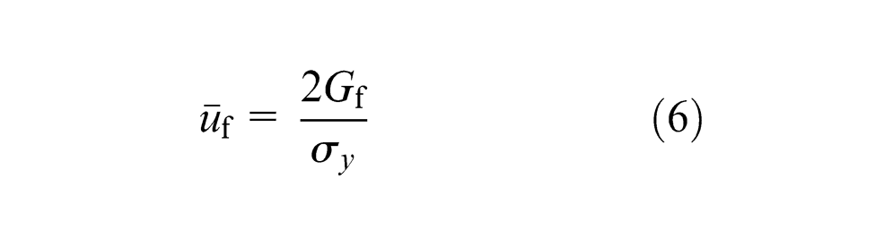
Equation (6) defines the equivalent plastic displacement at failure
An element loses its stiffness and load carrying capacity as parameter D approaches 1. These elements can be deleted (elements from chip separation zone) to realize chip separation.
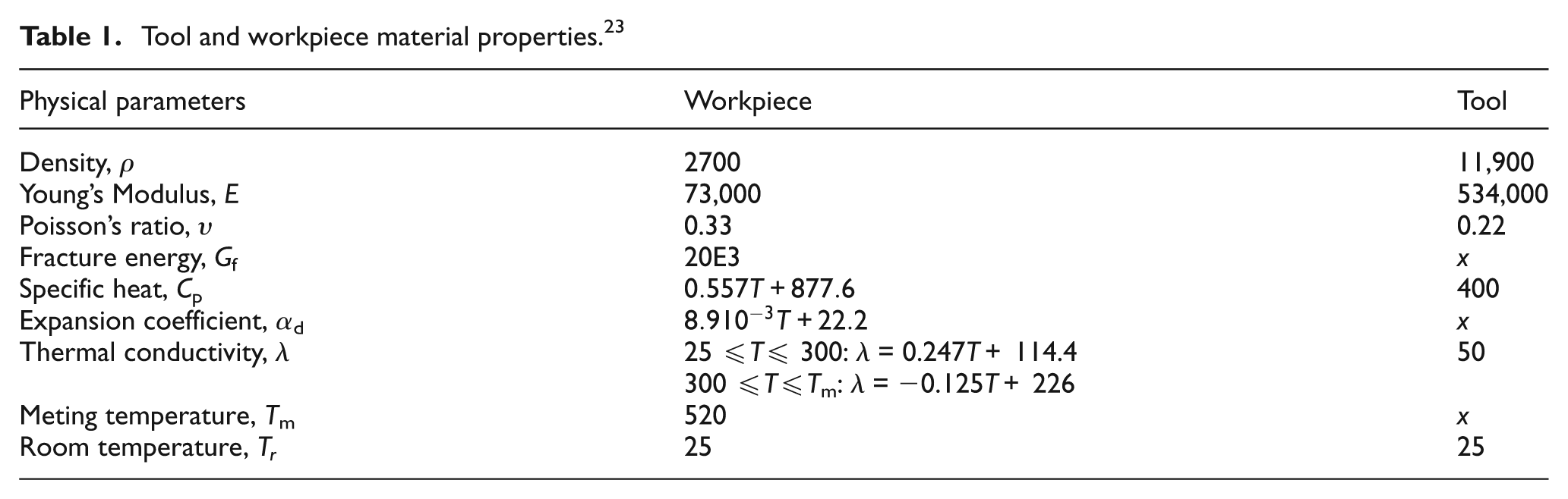
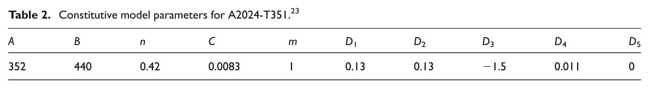
Thermo-mechanical properties of the cutting tool (tungsten carbide) and workpiece material (A2024-T351) are defined in Table 1. Material constitutive model properties are specified in Table 2.
Tool and workpiece material properties. 23
Constitutive model parameters for A2024-T351. 23
Simulation results and discussion
Orthogonal turning simulations results based on the FE models developed in section “2D and 3D FE models for orthogonal turning operation” have been presented here. Initially, 2D cutting simulations for machining of A2024-T351 for VC = 800 m/min, f = 0.3 and 0.5 mm/rev have been performed and comparison with the experimental results have been presented. Afterward, numerical simulations based on 3D model have been carried out for VC = 800 m/min, f = 0.3 and 0.5 mm/rev, aP = 4 mm. Experimental results concerning chip morphologies and cutting forces have been compared with numerical ones. Finally, simulation results with a modified version of the geometry of the tuning tool have been discussed.
Orthogonal turning simulations with 2D FE model
Figure 4 shows von Mises stress contours on the simulated chip morphology for VC = 800 m/min, f = 0.5 mm/rev. It can be seen that the segmented chip morphology with sharp teeth is fairly comparable with the experimental one (Figure 2(b)). Numerically obtained cutting forces were also found in good corroboration with the experimentally registered values (Table 3). Model has been exploited to predict the machined surface profile in terms of nodal displacement. As chip morphology dictates machined surface quality, 19 highly segmented chip morphology has originated a rippled surface topology.
Two-dimensional numerical chip morphology and surface topology for Vc = 800 m/min, f = 0.5 mm/rev.
Comparison of experimental and numerical cutting forces for VC = 800 m/min, aP = 4 mm with various feed rates.
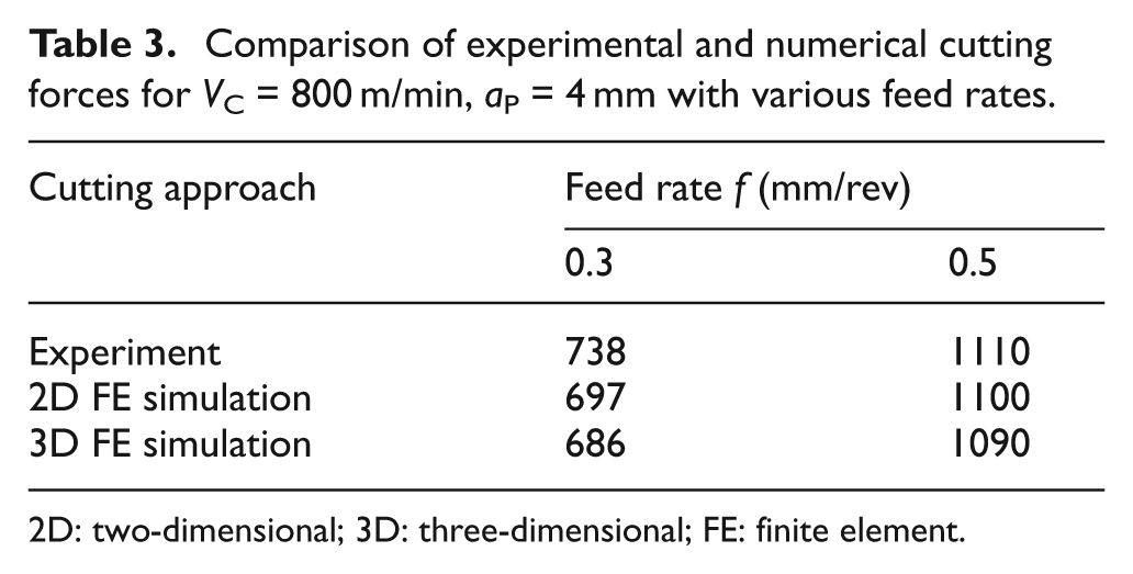
2D: two-dimensional; 3D: three-dimensional; FE: finite element.
Nevertheless, these simulations based on 2D model predict the results only on a plane section (XY plane with unit thickness) passing through the middle of the workpiece cutting depth aP, and not on the sections passing through the edges (discussed later in section “Orthogonal turning simulations with 3D FE model”). Therefore, 2D models cannot predict burr formation on workpiece edges.
Orthogonal turning simulations with 3D FE model
For qualitative prediction of the chip morphology and distribution of multiphysical values of interest at various sections along cutting depth (along Z-axis), 3D simulations were performed. 3D numerical chip morphology for VC = 800 m/min, f = 0.5 mm/rev, aP = 4 mm is shown in Figure 5. In general, numerical chip morphology (Figure 5(a)) is in good comparison with the experimental chip (Figure 2(b)). It can be figured out that the chip has evolved in the Z direction (out of plane deformation) in addition to its main evolution in XY-plane (along X and Y directions). Asad et al. 23 concluded that out-of-plane deformation is maximum during finishing operation. This latter phenomenon has produced dissimilar chip profiles at various sections (in XY-plane) along workpiece width. Figure 5(b) and (c) shows the chip morphologies in XY-plane section along cutting depth at Z = ±2 (workpiece edges) and Z = 0 (workpiece center), respectively. Less sharp chip segments at free edges (Figure 5(b)), than at central section (Figure 5(c)) can be clearly marked. This has generated non-identical machined surface topologies in these sections (Figure 6). This further suggests that the simulation results produced with 2D models, for example, sharply segmented chip morphology corresponding to XY plane section passing through center of workpiece width and not on the edges.
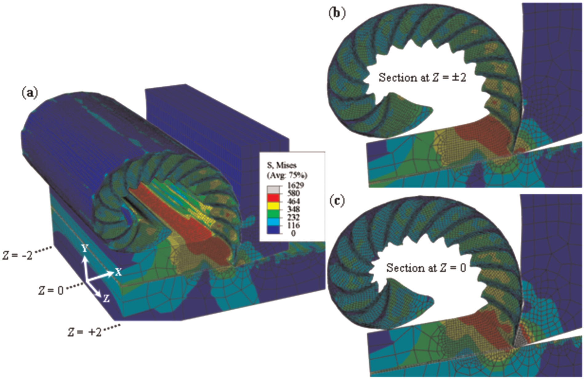
Numerical chip morphology for Vc = 800 m/min, f = 0.5 mm/rev, ap = 4 mm: (a) three-dimensional segmented chip evolution, (b) tool-chip section in XY-plane at Z = ±2, and (c) tool-chip section in XY-plane at Z = 0.
Numerically predicted surface topology of workpiece machined surface at various sections along cutting depth, for Vc = 800 m/min, f = 0.5 mm/rev, ap = 4 mm.
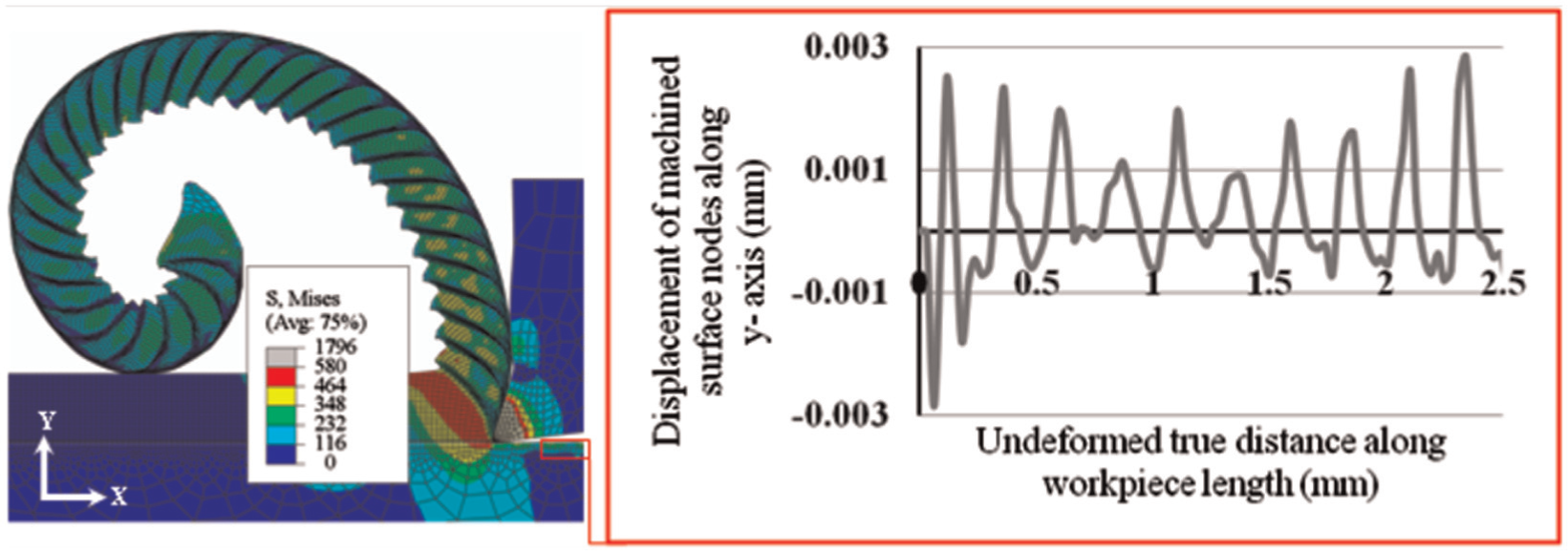
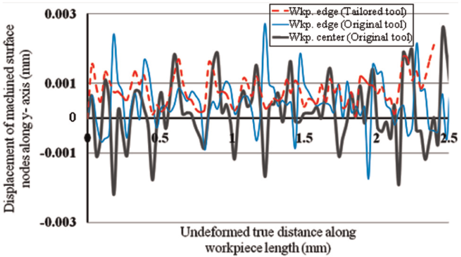
A considerable change in the frictional contact conditions leading to an increase in the contact pressure on edges of the tool–workpiece interface is attributed to the material flow along Z direction (out of plane deformation), as shown in Figure 7. This enhances the burr formation, as can be seen by displacements of machined surface nodes (at workpiece edges) along Z-axis (Figure 8). In Figure 8, where zero value along ordinate represents un-machined workpiece edge (at Z = +2), it can be seen that under the combined effects of out of plane deformation and increased frictional interaction, machined surface nodes (at edges) have been displaced up to 2 µm (quantitative prediction of burr). Choi et al. 22 have also employed a node displacement scheme to predict burr formation during the drilling process.
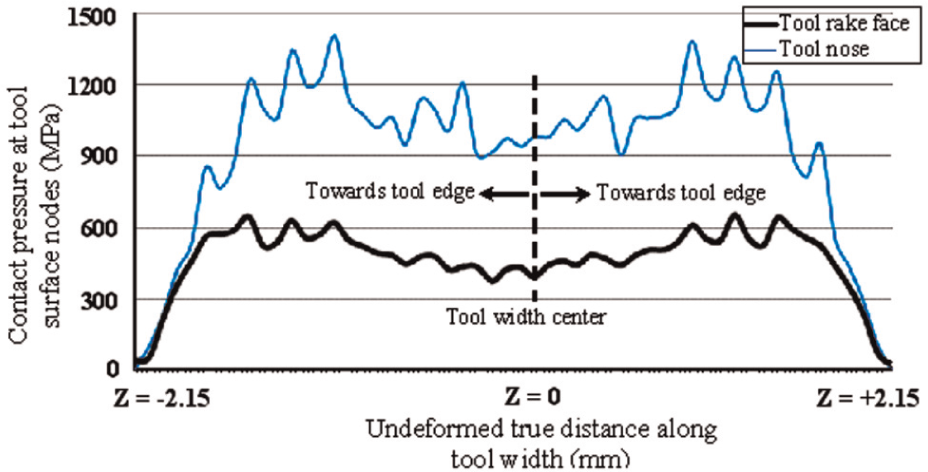
Contact pressure (MPa) evolution at tool cutting face along tool width (Z-axis) for Vc = 800 m/min, f = 0.5 mm/rev, ap = 4 mm.
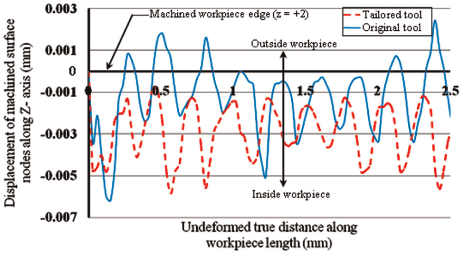
Numerically machined surface nodes displacement (at workpiece edge, Z = +2) for two cutting tool configurations, for Vc = 800 m/min, f = 0.5 mm/rev, and ap = 4 mm.
3D orthogonal turning simulations with tailored tool geometry
In this section, a modified version of the cutting tool to reduce burr formation has been suggested. Geometry of this new tool (Figure 9(b)) is comparable with the original tool geometry (Figure 9(a)), while no changes in cutting angles have been made.
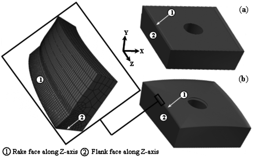
Tool used for turning simulations: (a) original tool and (b) modified convex-shaped tool.
The cutting simulations reproduced with this new tool have shown promising results in decreasing burr formation as a considerable drop in the displacement of workpiece nodes at edges can be figured out (Figures 6 and 8).
Furthermore, convex-shaped geometry of this new tool is useful in reducing the high-energy tool–workpiece contact in the beginning of machining operation (Figure 10). This latter contact has a detrimental effect on tool life.
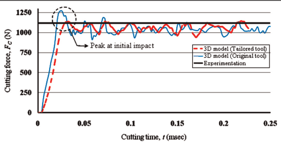
Cutting force plots with various cutting approaches for Vc = 800 m/min, f = 0.5 mm/rev, ap = 4 mm.
In Figure 11, it can be seen that continuous chip morphologies obtained with original and modified tools geometries are comparable with the experimental one (Figure 2(a)). However, in contrast to the chip produced with the new tool (Figure 11(b)), the chip produced with the original tool geometry (Figure 11(a)) is in self contact under similar cutting conditions. This suggests the likely production of long chips with the proposed tool configuration. Sandvik 25 has reported similar behavior of long fragmented chips with round-shaped turning tool inserts.
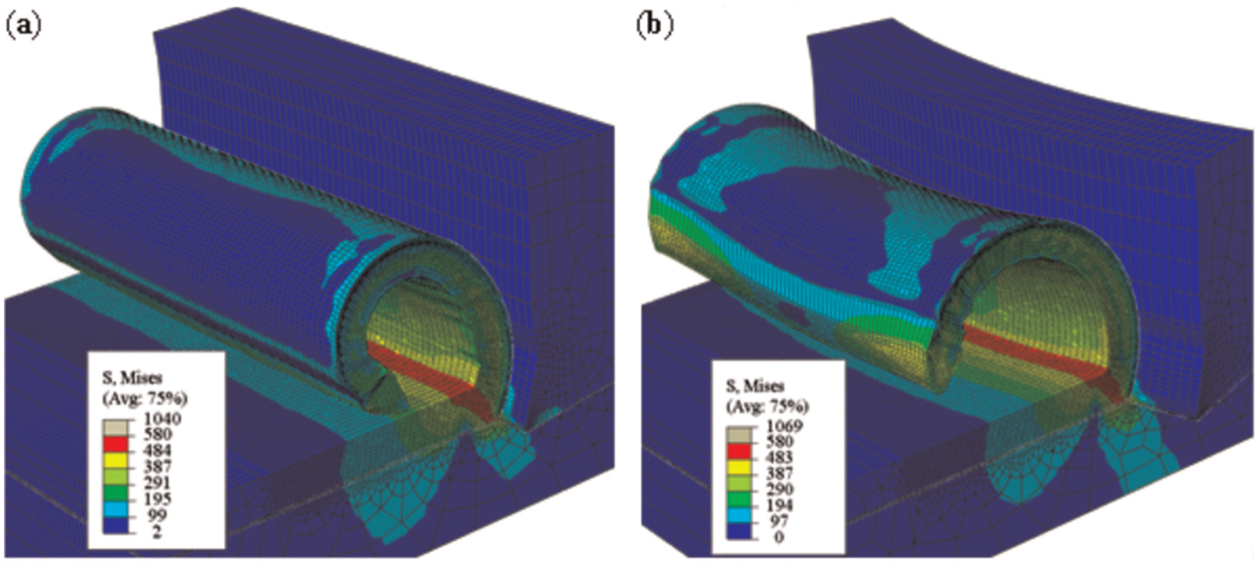
3D numerical chip morphology at cutting time t = 0.25 ms for Vc = 800 m/min, f = 0.3 mm/rev, ap = 4 mm with (a) original tool and (b) modified convex-shaped tool.
Conclusion
Finite element–based 2D and 3D turning models for machining of an aerospace grade aluminum alloy A2024-T351 have been developed. Model simulation results concerning chip morphologies and cutting forces were found in good corroboration with the experimental work. The findings of the work are outlined as follows:
Despite the numerical complexities and time penalty, it has been found that 3D models are necessary to improve the comprehension of cutting phenomenon and the qualitative prediction of multiphysical results of chip formation process.
Comparison of numerical chip morphologies obtained by executing the simulations based on 2D and 3D models shows that 2D models replicate the actual machining on a plane section (XY plane with unit thickness) passing through the center of cutting depth (center of workpiece width) and not at workpiece edges. This limits 2D cutting models for burr prediction.
Computational results based on 3D model show that during the cutting process, a small percentage of material volume flows along the Z direction (out of plane deformation) toward workpiece edges. This changes the frictional contact conditions at the edges of tool–workpiece interface as indicated by the increased contact pressure. Simultaneous effects of out-of-plane deformation and increased frictional interaction on edges during cutting simulation have displaced machined workpiece nodes along Y and Z directions (burr prediction).
In this study, a modified version of a particular turning tool has been proposed. The convex-shaped geometry of the proposed tool is quite helpful in reducing the frictional contact at the edges of the tool–workpiece interface and burr formation, which has been verified by reproducing the numerical simulations with this tool. The tool was also found helpful in reducing the high-energy initial impact of the tool with the workpiece material. However, due to reduced tool–workpiece frictional interaction, the proposed tool is susceptible to produce long chips.
Finally, the developed models will certainly be useful in better understanding the multiphysical cutting process. This shall be eventually effective in improving the machining efficiency.
Footnotes
Appendix 1
Acknowledgements
Authors wish to acknowledge the technical and administrative assistance provided by Prof. J.-F. Rigal and Dr F. Girardin to conduct the experiments in LaMCos Laboratory.
Declaration of conflicting interests
The authors declare that there is no conflict of interest. Note that the manufacturers Sandvik and Kistler are not liable for the experimental results. The names are provided only to enlighten the readers.
Funding
This research received no specific grant from any funding agency in the public, commercial, or not-for-profit sectors.