
Abstract
High-precision parallel alignment between the substrate and the template is of great importance for nanoimprint lithography. Recently, flexure-based mechanism is commonly employed to realize high-precision parallel alignment; however, stiffness in imprint axis is hard to guarantee. In this article, a new parallel alignment device is proposed, which enables the imprinting force bypass the delicate alignment mechanism, thus eliminating the side effects of imprint forces and ensuring parallel alignment able to be carried out properly. A spherical air bearing is adopted in the device for the above-mentioned purpose through decoupling the nonuniform imprinting forces distributing on the template, allowing only the torque to reach the delicate alignment mechanism. The structural parameters of the air bearing are optimized through modeling and analysis of the bearing performances in terms of load-carrying capacity and stiffness. For the bearing preload, a set of permanent magnets are employed. The preliminary experimental results show that high load capacity and stiffness are achieved, which are consistent with the derived model.
Keywords
Introduction
Nanoimprint lithography (NIL) is a novel technique utilizing the imprint force to transfer predefined micro-/nano-level patterns from a template to a substrate. 1 It has been flagged as the next-generation lithography tool due to its simplicity, low cost and relatively high throughput. Recently, this technology has been widely applied in the fabrication of electrical,2,3 biological,4,5 and optical6–8 devices. Considering the small imprinted features, pattern transfer fidelity is critical and significantly depends on the alignment system.9–11 Particularly, nonuniform surface contact between the template and the substrate will cause a defective pattern transfer to the substrate. Consequently, a high-precision parallel alignment device is indispensable in an advanced NIL machine to guarantee the quality of the transferred patterns.
Parallel alignment needs to perform an out-of-plane (θx and θy) adjustment to bring the template in parallel with the substrate. Since actuator and sensors usually have limited precision, wedge error cannot be eliminated completely through active alignment. Therefore, flexure-based mechanisms are usually adopted to compensate for the residual error passively by mechanical deformation.12,13 A number of research works on development of high-precision parallel alignment devices have been published so far. Johnson 14 proposed a compliant mechanism with distributed flexible rings and installed it on a substrate stage for the parallel surface contacts. Choi et al. 15 designed a 2–degree of freedom (DOF) (θx and θy) compliant tilting template stage for a multi-step NIL machine. The orientation axes are arranged at the template–substrate interface to eliminate the lateral motion errors caused by change in orientation angles. Dong et al. 16 presented a 6-DOF stage based on a parallel mechanism with compliant joints. The stage consists of an inner mechanism and an outer mechanism. They are used for the active in-plane alignment and the passive out-of-plane alignments, respectively. Fesperman et al. 17 designed a multiscale alignment and positioning system. The parallelism adjustment is driven by three lead zirconate titanate (PZT) actuators through compliant mechanism perpendicular to the template plane.
The aforementioned works achieved excellent alignment performances through passive compensation. However, the low-stiffness compliant mechanisms are commonly arranged in the force loop and endure the total imprint force. As is known, the required imprinting force may vary from a few Newton to thousands of Newton for different types of NIL process. In cases of large imprint forces, such design may result in the compliant mechanism undertaking a significant deformation in unwanted directions, causing serious pattern transfer degradation. How to realize passive error compensation as well as maintain high imprint capacity remains a key problem to be solved.
Considering the fact that compliant mechanism is indispensable for achieving passive alignment, a main conceptual pillar to solve the deformation problem is force-decoupled design, which converts the nonuniform imprinting force distributed on the template to a torque and a vertical force about the spherical center. The torque drives the compliant mechanism to realize passive parallel alignment, while the vertical force is sustained by the high-stiffness structure without affecting the compliant mechanism.
This article presents the design of novel parallel alignment device to address the negative effect of the imprint force on the compliant mechanism. It adopts a spherical air bearing, serving as a frictionless spherical joint, in conjunction with a special compliant connector to perform force-decoupled parallel alignment. The proposed design solves the problem that the compliant mechanism cannot work properly under a large imprint force. By incorporating our force-decoupled alignment device, current NIL systems will have the potential to perform high-precision alignment under different force requirements.
Structure design of the parallel alignment device
NIL is a nanoscale structure manufacturing process, which has strict requirements on parallel alignment between the template and the substrate for generating a pattern layer with uniform thickness on a large imprint area. This section will first introduce basic background information about NIL and then present the structure design of a novel parallel alignment device for NIL.
Process of NIL
NIL was originally proposed as a promising technology for the fabrication of micro-/nano-structures in 1996, 1 and since then researchers around the world have developed many variations,18–20 including ultraviolet nanoimprint lithography (UV-NIL), step and flash imprint lithography (SFIL) and micro-contact nanoimprint lithography (µCP). The general processes of the most basic type of NIL, thermal nanoimprint lithography (T-NIL), are illustrated in Figure 1(a).
Step 1. Coating: a thin layer of thermoplastic photoresist is spin-coated onto the substrate, which is usually made of silicon, glass or polymer.
Step 2. Alignment and pressing: a template with predefined patterns is aligned with the substrate to eliminate the overlay error and the wedge error. When the photoresist is heated up above the glass transition temperature, the template is pressed to let the softened photoresist fill in the cavities of the template. Due to relative high viscosity of the photoresist, high imprint force is required to improve the filling process in this step.
Step 3. Demolding: after the temperature is lowered down and the photoresist is solidified, the template is removed from the substrate. Since the template is usually coated with anti-adhesion material, the required pulling force for demolding is only a few tens of Newton.
Step 4. Etching: finally, residual layer is removed through etching process.
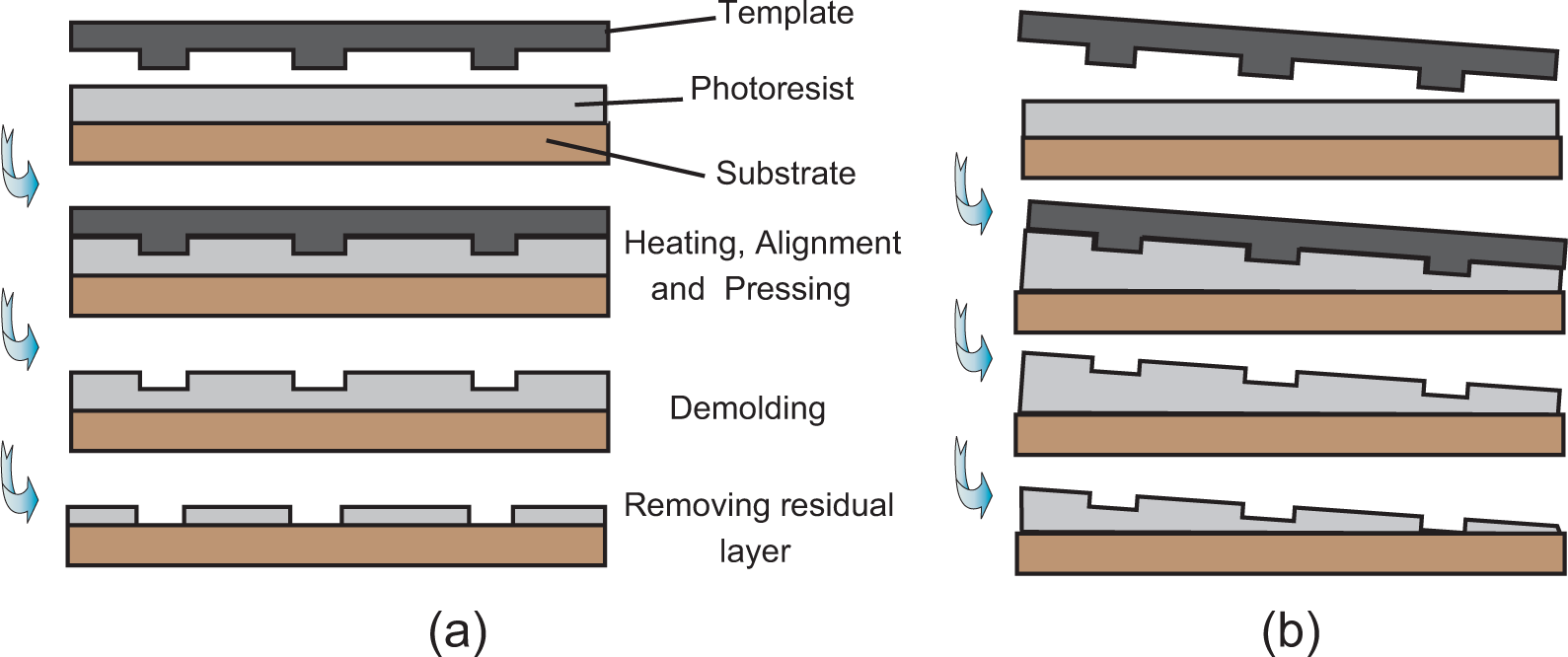
Nanoimprint lithography: (a) process of thermal nanoimprint and (b) wedge error caused by poor parallel alignment.
To realize NIL over a large area, high-precision parallel alignment between the template and the substrate is crucial before the imprint force is applied. Figure 1(b) shows the parallel misalignment between the template and the substrate, which generates an uneven photoresist layer, seriously reducing the fidelity of duplicated patterns.
Among the existing NIL technologies, UV-NIL or µCP usually requires a small imprint force due to the liquid state of the photoresist, while T-NIL needs large imprint force to press the template into the photoresist in glassy state. How to achieve high load capacity while avoiding the negative effect on the compliant mechanism should be solved. Besides, overlay precision is an important criterion for NIL equipment; hence, how to avoid parasitic movement in the horizontal plane during the parallel alignment process should be addressed in our design.
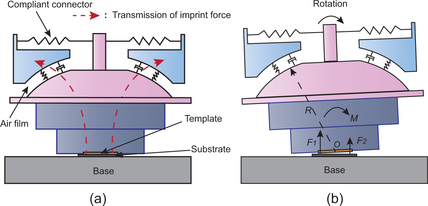
Our design is targeting the parallel alignment problem for two common types of NIL process, T-NIL and UV-NIL. From the mechanical point of view, the two types of NIL process are difficult to accomplish with one device. UV-NIL requires a smaller imprint force (imprint pressure < 0.5 MPa), thus allowing the incorporation of compliant mechanism to realize high-precision active/passive tilt alignment. While for T-NIL, considering the high viscosity of photoresist, high imprint force (imprint pressure > 3 MPa) and stiffness in the vertical direction should be guaranteed to fill the cavities in the template and form functional patterns with high fidelity. High imprint force may cause undesired parasitic deformation of the compliant mechanism or even damage the compliant mechanism. How to make the proposed device suitable for the two types of nanoimprint processes is the key problem in the mechanical design. Several basic technical requirements we especially pay attention to are summarized in Table 1.
Parameter specifications of the imprint head.
Structure description
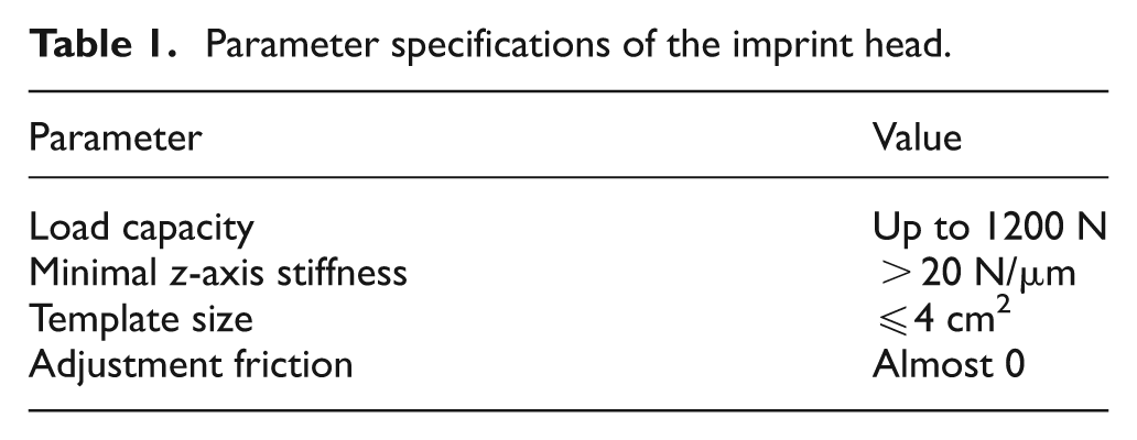
The proposed parallel alignment device for NIL mainly consists of a spherical air bearing, a compliant connector and a magnetic preload structure as shown in Figure 2.
Schematic diagram of the parallel alignment device.
A spherical joint is employed for performing parallel adjustment. To achieve high adjustment precision, low friction between the contacting surfaces of the spherical joint is desired. For this reason, a spherical air bearing is applied in our design. Unlike contact roller bearings, air bearings utilize a thin film of pressurized air to separate the surfaces that would otherwise be in contact with each other. Being noncontact, air bearings avoid the traditional bearing-related problems of friction, wear and lubricant handling and provide distinct advantages in precision positioning applications.21,22 The spherical air bearing proposed in this article consists of a spherical cup, a spherical head, an air inlet and a seal cap (see Figure 2). Pressured air is injected through the air inlet and spreads in the gap between the spherical cup and the head for lubrication. To avoid side slip during the process of alignment, the spherical center of the bearing is designed to be coincident with the center of the template.
To balance the gravity of the spherical head and strengthen the stiffness of the air film, annular permanent magnets are embedded in the seal cap and the spherical head to provide preload. The thickness and number of the magnets can be altered to adjust the magnetic force. Pieces made of nonmagnetic materials, for example, aluminum, can also be filled in the slot to further change the preload.
A compliant connector, consisting of a clamping hole, four flexible joints and an outer frame, is adopted to connect the spherical head with the seal cap (see Figure 2). The flexibility of the compliant connector allows the template to compensate for wedge error passively. Due to the special topology, the connector has low translational stiffness in x, y and z directions but high rotational stiffness around z-axis. The clamping hole, holding the connection rod, can provide fine passive adjustments in a small range due to the flexure characteristic. The adjustments in x and y directions rotate the spherical head for a parallel alignment, and the adjustment in z direction adapts the relative motion between the spherical head and the spherical cup caused by the compressibility of the air film under different imprint forces.
Three eddy current sensors are fixed around the spherical cup to measure the distances from the sensor probes to the reference plane, which is in the same plane with the template. Once the distances are obtained, the attitude of the template relative to the spherical cup can be calculated. More importantly, the thickness of the air film can be obtained from the measurement results. By incorporating the stiffness information of the air film, the imprint force applied can be calculated for the control problem.
Working principle
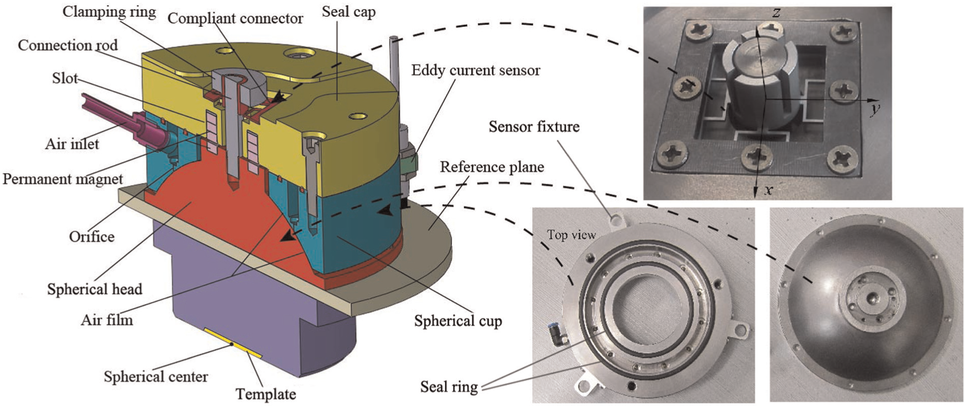
A conceptual sketch that illustrates the principle of the proposed parallel alignment device is shown in Figure 3. The compliant connector is configured perpendicular to the imprint axis as shown in Figure 3(a). When an imprint force is applied, the spherical air bearing transmits the vertical imprint force through the air film to rigid mechanical structures, while the compliant connector is outside the imprint force loop. Therefore, the compliant connector is fully decoupled from the imprint force, which means that the imprint force will not cause extra deformation on the compliant connector. The characteristic of imprint force decoupling allows the parallel alignment device to meet different imprint force requirements for all kinds of NIL.
Working principle of the alignment device. (a) Transmission of imprint force under normal imprinting (b) Passive adjustment in case of a wedge error
When wedge error exists between the imprint template and the substrate as shown in Figure 3(b), a torque caused by the nonuniform contact force will drive the spherical head to make parallel adjustment until the error is fully compensated. The compensation process is very sensitive to the torque due to the frictionless property between the two spherical surfaces.
During the demolding process, the template should be pulled out from the substrate. The stored energy in the compliant connector will be released and is prone to cause a demolding angle between the template and the substrate. Since the photoresist is solidified, a small demolding angle within
Structural modeling and analysis
Compliant connector
To accommodate the rotation of the spherical head, the compliant connector should have 5 DOFs, including the translational DOFs about the x-, y- and z-axes and the rotational DOFs about the x- and y-axes. The designed compliant connector consists of four chains in symmetric layout, with the dimension parameters shown in Figure 4. For the proposed design, the rotational stiffness about the z-axis is much higher and thus is considered as a rigid connection. The stiffness of the other 5 DOFs will be derived as follows.
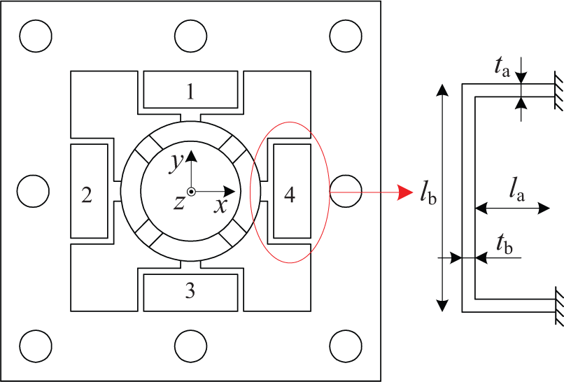
The 5-DOFs compliant connecter and the definitions of dimensional parameters.
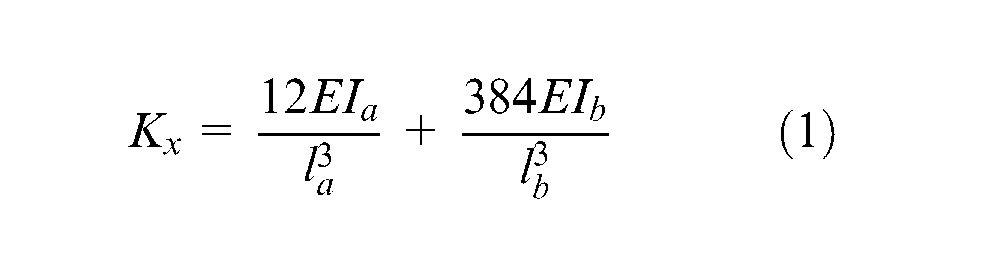
The designed compliant connecter is symmetric about x- and y-axes, so its stiffness matrix has a diagonal matrix form and can be expressed as
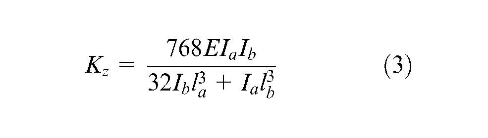
Similarly, the rotational stiffness about the x- or y-axis and translational stiffness about the z-axis can also be derived as follows
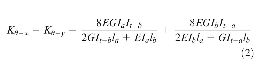
where E (Young’s modulus) is 71.7 GPa and G (shear modulus) is 26.9 GPa for the selected aluminum alloy.
The dimensional parameters of the compliant connector are given in Table 2, and with the parameters, the stiffness in the five directions are obtained as follows:
Dimensional parameters of the compliant connector.
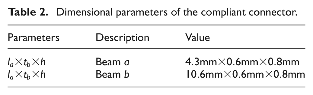
The translational stiffness of flexural beams in z-axis is extremely low compared with that of the air film discussed in the following section, so the influence of the compliant connector can be neglected when analyzing the load capacity and the stiffness of the imprint head. The low translational and rotational stiffness of the connector increases the parallel alignment sensitivity.
Modeling and optimization of the spherical air bearing
The air film of air bearing, which can be equivalent to a spring and a damper, has the lowest stiffness in the path of the imprint force. The load capacity and stiffness of the air film play key roles in the precision and stability of the imprint head. Imprint force that exceeds the load capacity may cause the two separated spherical surfaces to contact with each other, which will lead the parallel alignment to failure or even destroy the spherical surfaces. For this reason, high load capacity and stiffness of the air bearing are desired to minimize the deviation of the template center from the spherical center under an imprint force. In this section, the load capacity and the stiffness of the air bearing are explored and optimized.
Numerous studies show that the geometries of air bearings and the operational conditions determine the load capacity and stiffness. In this section, the load-carrying capacity and the stiffness of the air film are studied based on a mathematical model and validation experiments.
The schematic diagram of the bearing employed in the parallel alignment device is shown in Figure 5. It mainly consists of a spherical head, a spherical cup and some necessary air paths. Initially, compressed air is injected into the ring groove with the pressure of
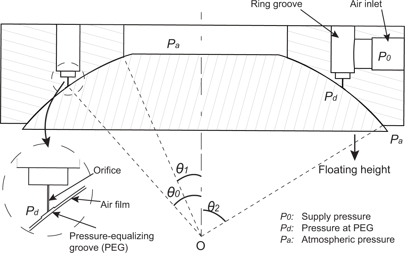
Schematic diagram of the spherical air bearing.
The pressure distribution in the air film can be obtained through Navier–Stokes equations, which describe the motion of fluid substances. In order to simplify the analysis, the following assumptions are established.
The inertia forces of air due to acceleration can be neglected compared with the frictional forces due to viscous shearing; laminar flow conditions exist at all points in the gas film; the pressure is constant over any section normal to the direction of the flow; there is no slip at the boundaries between the fluid and the spherical surfaces or the spherical structure adopted; and the pressure in the PEG at
With the above assumptions, in the spherical coordinates
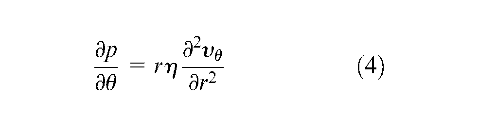
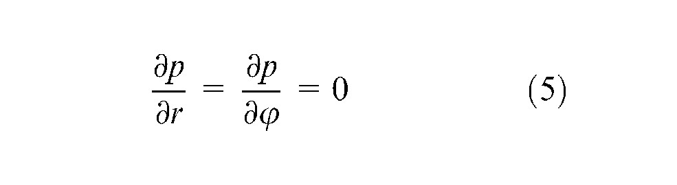
where
Since R is a constant,

As it is assumed that there is no slip at the boundaries between the fluid and the spherical surfaces, boundary conditions can be written as
The air film is divided into two parts by the PEG, and now we consider the upper part first. The mass flow at
Substituting equation (8) into equation (9) yields
By substituting equation (6) into equation (10) and separating variables, we have
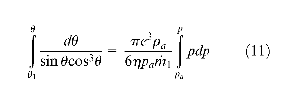
By solving the integral, we get
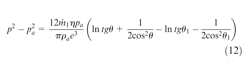
It is assumed that
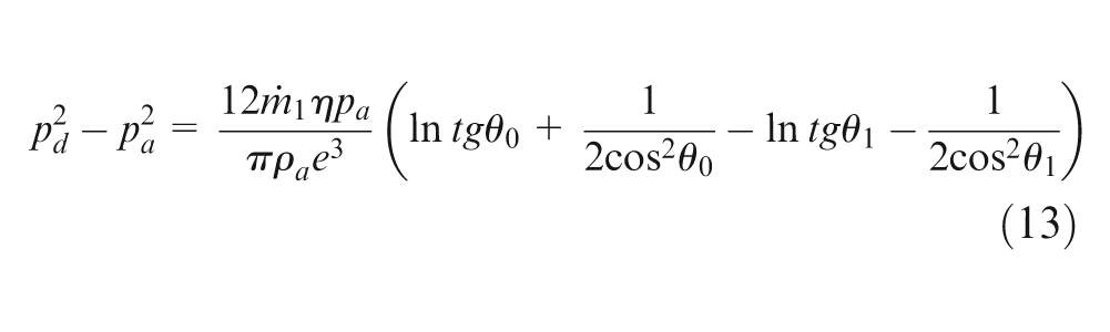
Dividing equation (12) by equation (13) and solving P, the pressure distribution is obtained
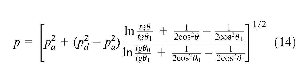
where
where
Since the pressure distribution p is obtained, the vertical force generated by the air film can be calculated by the integration of p in the spherical region. Subtracting the force generated by environment pressure
Thus, the static stiffness of the air bearing can be obtained by
The diameter, number and position of the orifices have significant influences on the performances of the spherical air bearing, such as the load capacity and the air consumption. It is assumed that the orifices are equally distributed in a circle, which can be described by
There are many possible combinations of these parameters. To understand how each parameter affects the performance of the air bearing, two of them are fixed and only one parameter is changed in the following numerical experiments.
From the results in Figures 6–8, the following can be concluded.
As the diameter of the orifices increases, higher load capacity is obtained, while the peak stiffness decreases. Even though smaller orifice results in higher stiffness, it will in turn increase the manufacturing cost. Besides, higher requirements for the air filtering system should be met to prevent the particles in the air from sticking in the orifice.
Larger number of orifices results in higher load capacity and smaller peak stiffness. When the peak stiffness is obtained at a smaller floating height, the spherical error of the air bearing should be further reduced to avoid contact.
A maximum load capacity can be obtained with the distribution angle
Influence of the diameter of the orifices: (a) load capacity versus floating height and (b) stiffness versus floating height.
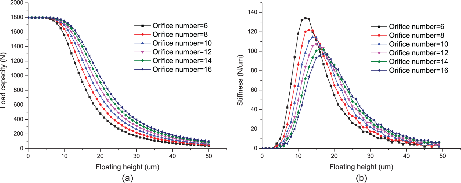
Influence of the number of the orifices: (a) load capacity versus floating height and (b) stiffness versus floating height.
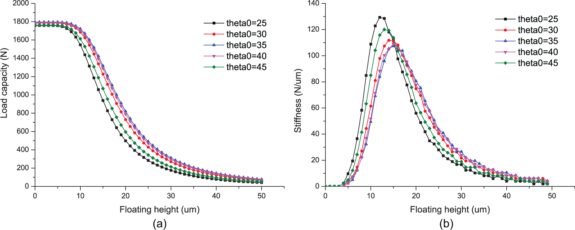
Influence of the distribution of the orifices: (a) load capacity versus floating height and (b) stiffness versus floating height.
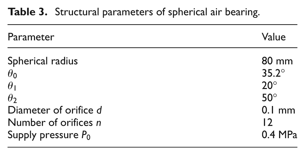
The structural parameters of the spherical air bearing adopted in the parallel alignment device are finally determined and given in Table 3.
Structural parameters of spherical air bearing.
Results and discussions
Load capacity and stiffness test for the air bearing
A verification experiment (with the parameters in Table 3) is set up to explore the relationship between the floating height and the applied imprint force as shown in Figure 9. The air bearing’s working state is measured by a data acquisition system, including a data acquisition card, three eddy current displacement sensors, load cells and a computer with data processing software. The eddy current sensors mounted around the spherical cup of the bearing are employed to measure the distance to the measurement plane, which is attached to the spherical head. To reduce the measurement error caused by a possible tilt of the bearing head, the output of the three eddy current sensors is averaged to indicate the distance. The load applied to the bearing is measured by three load cells, which are arranged in a symmetrical layout under the spherical head.
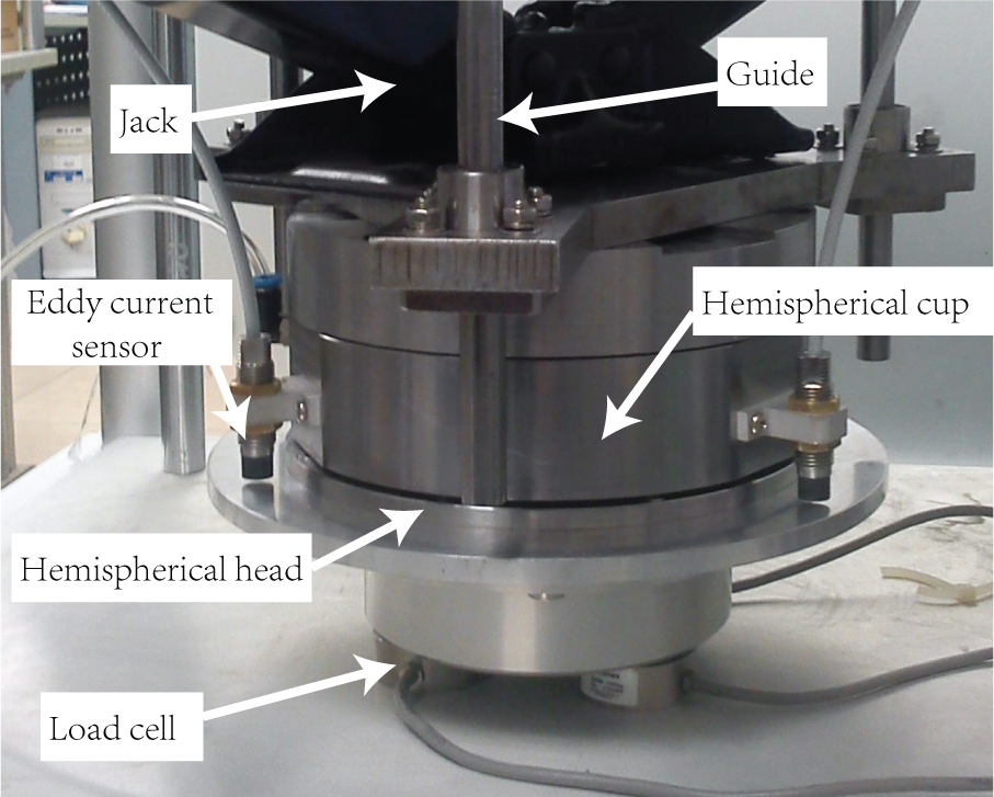
Experimental setup.
Mechanical deformation of the air bearing must be taken into consideration in the verification experiment. When the air film is compressed to a thin film with the thickness of several or tens of microns, the stiffness of the air film is significantly increased; therefore, the spherical cup or the spherical head can no longer be considered as a rigid body relative to the air film. As the finite element simulation in Figure 10 shows, the deformation of the spherical cup may draw the sensor closer to the measurement plane, thus the air film seems to change more significantly, which decreases the measured stiffness of the air film. In order to delimitate the additional displacement caused by mechanical deformation, load experiments are done under two conditions: (1) without pressured air supply and (2) with pressured air supply at 4 atm. The experimental results are shown in Figure 11. Compared with plot (1), the extra output of the distance under the same imprint force in plot (2) is caused by the air film, thus the gap between the two plots represents the floating height of the spherical head. Since the measurement points are not equally spaced in our experiment, subtraction between the two plots is performed after interpolations, and the results are shown in Figure 12.
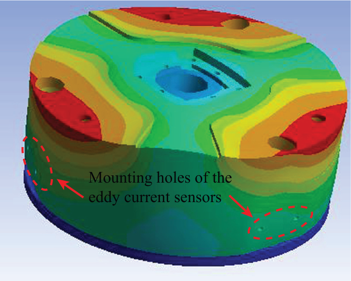
Deformations of spherical cup caused the imprint force.
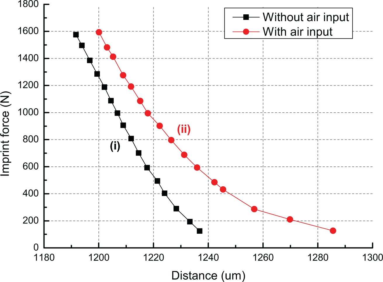
Results of load experiment. The x-axis represents the measured distance from sensor probes to the measurement plane and the y-axis represents the imprint force applied to the air bearing.
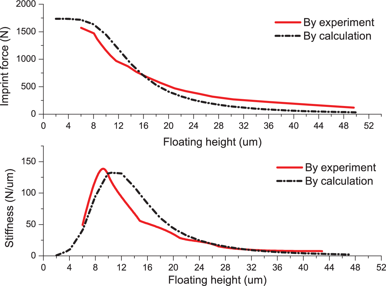
Results of the verification experiment: load capacity and stiffness.
The results from theoretical calculations and verification experiments are well conformed. As the floating height increases, the load capacity decreases in a nonlinear form. When the floating height approaches 0, the maximum load capacity is obtained, but the stiffness is very low. The bearing cannot work under this condition because a slight increase in the external load will cause the contact of the head and the cup. When the floating height arrives at about 10 µm, the maximum stiffness is obtained. As the floating height exceeds 30 µm, the load capacity and stiffness are both very low. So, an ideal operating point is around the floating height with maximum stiffness, where the behavior of air bearing is close to a rigid body.
Stiffness improvements
Stiffness is a most concerned problem for NIL systems to produce high-precision patterns. However, it can be concluded from the results in Figure 12 that the stiffness of the air bearing is extremely low when there is not enough load applied on it. The low stiffness of the device will result in poor performances, such as vibration, low precision and high air consumption. To solve this problem, magnetic preload is proposed in section “Structure design of the parallel alignment device” for its simple structure and 0 energy consumption. Details of the preload structure are shown in Figure 13. In this section, the performance of the parallel alignment device incorporating the magnetic preload is studied through simulations and experiments.
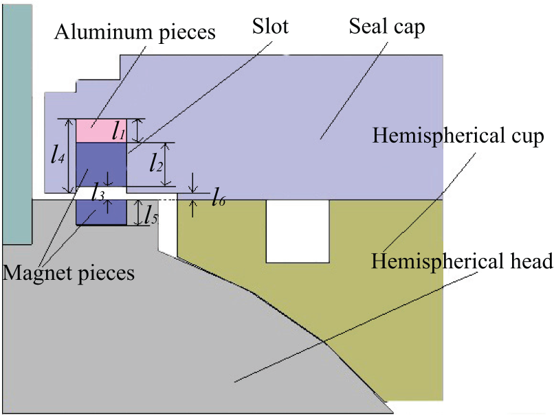
Configuration of the permanent magnetic preload (cross-sectional view).
As shown in Figure 13, the annular pieces made of magnet (Nd-Fe-B) and aluminum are embedded in the slot to generate a desired attraction. By altering the combination of the annular pieces, the attractive force can be adjusted to maintain the stiffness in a reasonable range. In order to generate strong magnetic field, Nd-Fe-B (a strongest type of magnetic material) is applied. Moreover, stainless steel with high permeability is applied as the material of the seal cap, spherical cup and spherical head to form a perfect magnetic loop and decrease the magnetic leakage.
Since the preload force can be adjusted by changing the applied magnets, four different preload structures are designed with the cut-views shown in Figure 14. Besides preload structure, floating height is another factor affecting the magnetic force by altering the air gap of the magnetic loop. For the four different configurations, the floating height is set from 0 to 30 µm with the simulation step of 1 µm.
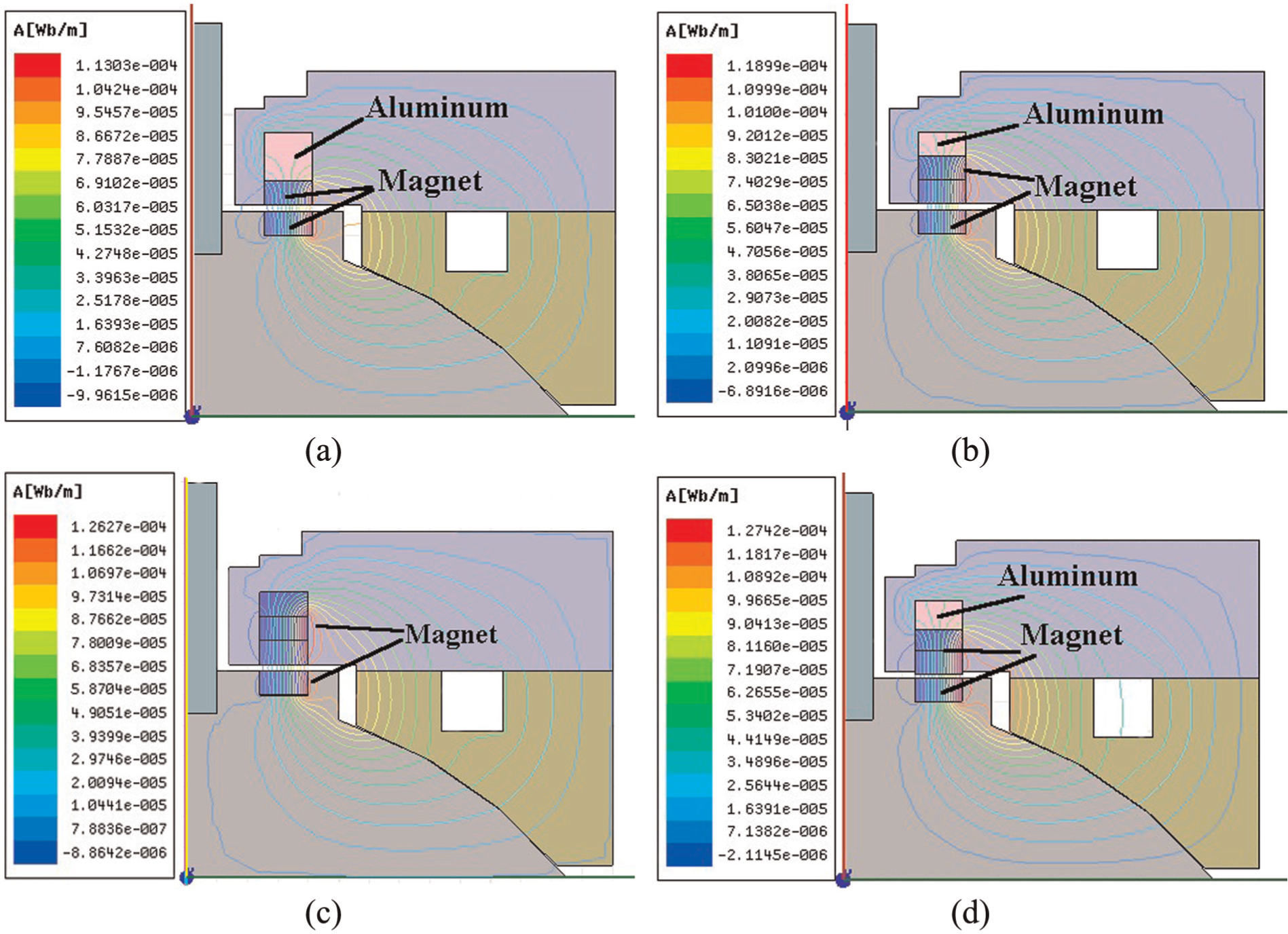
Four different configurations for the magnetic preload and the corresponding simulation results: (a), (b), (c) and (d) are four different configurations with aluminum and magnetic pieces in the slot, and the thickness of the pieces is set as follows: (a) aluminum: 8 mm, magnet: 4 mm; (b) aluminum: 4 mm, magnet: 4 × 2 mm; (c) aluminum: 0 mm, magnet: 4 × 3 mm; and (d) aluminum: 4.5 mm, magnet: 4 × 2 mm.
The simulation results are shown in Figure 15. It can be concluded that the configuration of the preload structure exerts a strong influence on the magnetic force. The results also indicate that the magnetic force decreases as the floating height increases. However, the total decrement in magnetic force is only about 10 N, which can be neglected in practical application where the normal range of the floating height is usually several microns. Besides, a pulling force, which is usually a few tens of Newton, is required when removing the template from the substrate. By discharging the air in the spherical air bearing, a pulling force over 200 N can be obtained, satisfying the demolding application.
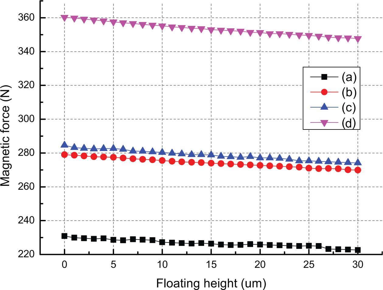
Simulation results of the magnetic force under four different configurations.
The load capacity and the stiffness of the imprint head incorporating magnetic preload structure (d) are measured experimentally (experimental setup is similar to that shown in Figure 11) with the results shown in Figure 16. Due to the preload, the maximum load capacity is reduced from about 1600 to 1250 N. However, the air film is compressed by the magnetic force, and the initial floating height is lowered to about 25 µm, resulting in a higher initial stiffness. The results verify the effectiveness of the magnetic preload structure.
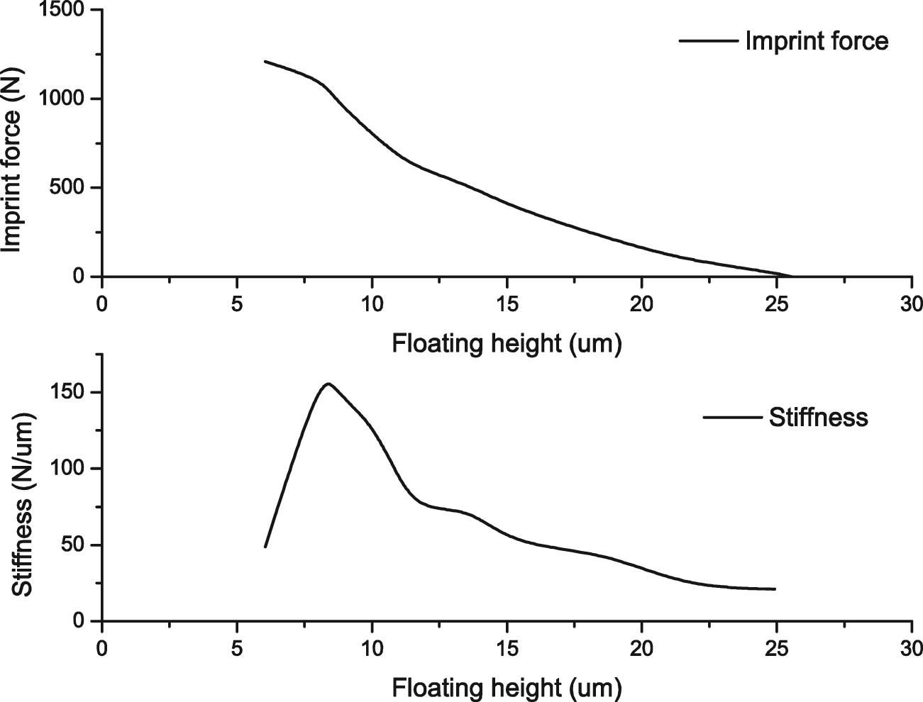
Measurement results of load capacity and stiffness of the imprint head with magnetic preload.
Conclusion and future works
Based on the concept of force decoupling, a parallel alignment device for NIL is proposed in this article. The novel structural design provides several important advantages against the existing parallel alignment devices.
First, it employs a spherical air bearing as a spherical joint to realize frictionless parallel alignment as well as force decoupling, thus high alignment precision is guaranteed even under large imprint force.
Second, the parasitic lateral motion between the template and the substrate during parallel alignment process is minimized by overlapping the template center with the spherical center.
Finally, a permanent magnetic preload structure is designed to improve the stiffness of the imprint head.
To study the load capacity and stiffness of the spherical air bearing, a theoretical model is built based on Navier–Stokes equations. Utilizing the derived theoretical model, we optimized the structural parameters of the air bearing. The model is verified through a loading experiment on the developed prototype.
The magnetic preload structure for stiffness improvement is studied through simulations and experiments. Results show that the magnetic force is easy to adjust by altering the preload configurations and maintains almost the same value in the working distance. By applying magnetic preload, a higher initial stiffness is achieved. For T-NIL and UV-NIL applications, the requirements of imprint force and pulling force can be met by our device.
Footnotes
Acknowledgements
This article is partially based on a paper presented on 2nd IFToMM Symposium on Mechanism Design for Robotics. The articles presented at the symposium were not indexed, and no copyright was acquired by the symposium. There is no restriction for the content to be published in other journals.
Declaration of conflicting interests
The authors declare that there is no conflict of interest.
Funding
This work is supported by the National Natural Science Foundation of China (grant no. 91023036).