
Abstract
It is well known that the multi-axis machining technology has been developed into a key technique applied in the manufacturing field. The machined surface integrity is one of the most important factors influencing the performance of the produced components. Hence, this research concentrated on the machined surface integrity induced by the multi-axis milling operation with different inclination angle combinations. In this research work, the cutting conditions of the conventional or up-milling process with tool orientations were divided into eight different types, and the machining characteristics corresponding to different cutting strategies were discussed. The varying conditions of surface topography, texture and other machining features induced in machining process which corresponds to different inclination angle combinations were analyzed by geometrical analysis, and the surface roughness and linear profile along specific directions on the machined surface were also investigated. There is a special corresponding relationship between the rotation angle and tool tilt and lead angles. Better surface roughness could be achieved when rotation angles are 0° (positive lead), 60° (combination of positive tilt and positive lead), 90° (positive tilt) and 330° (combination of negative tilt and positive lead). Then, the samples used for study of the metamorphic layer were produced by lapping and polishing process, and the macro hardness (HL) and micro-hardness (HV) of the top machined surface were investigated. According to the measured results of both Leeb hardness and micro-hardness, higher surface hardness could be obtained under rotation angles of 60° (combination of positive tilt and positive lead), 120° (combination of positive tilt and negative lead) and 210° (negative tilt and negative lead). Moreover, the variations of the micro-hardness along the depth direction of the samples were studied. Finally, discussions on the machined surface residual stresses in both feed and cross-feed direction were carried out. Compressive surface residual stress in both feed and cross-feed direction could be generated when rotation angles are 210° (combination of negative tilt angle with smaller value and negative lead angle with larger value) and 330° (combination of negative tilt angle with smaller value and positive lead angle with larger value). Generally, the evaluation indicators of surface integrity are not all very satisfying under one special cutting condition with a certain inclination angle combination, and the optimal cutting parameters should be selected based on the specific application requirements. Finally, the optimal tool orientations and related cutting parameters were recommended, and further studies of the related topics were also presented.
Introduction
The various manufacturing technologies have been widely used for making products to satisfy the people’s increasing needs of material in modern times, and the multi-axis machining is one of the most significant technologies in the machining field. Many scholars have paid their attention to the understanding and application of this special machining method. Surface integrity is the most important research area for some components requiring high performance.
The key features or characteristics of the machined surface mainly consist of surface topography, surface texture, surface roughness, micro-hardness, residual stresses and microstructure, and the details about these features are presented in Table 1. This work mainly concentrated on the surface topography, surface texture, surface roughness, micro-hardness (surface and cross-section micro-hardness) and surface residual stresses of the machined surface of multi-axis ball end milling process.
Key features of the machined surface
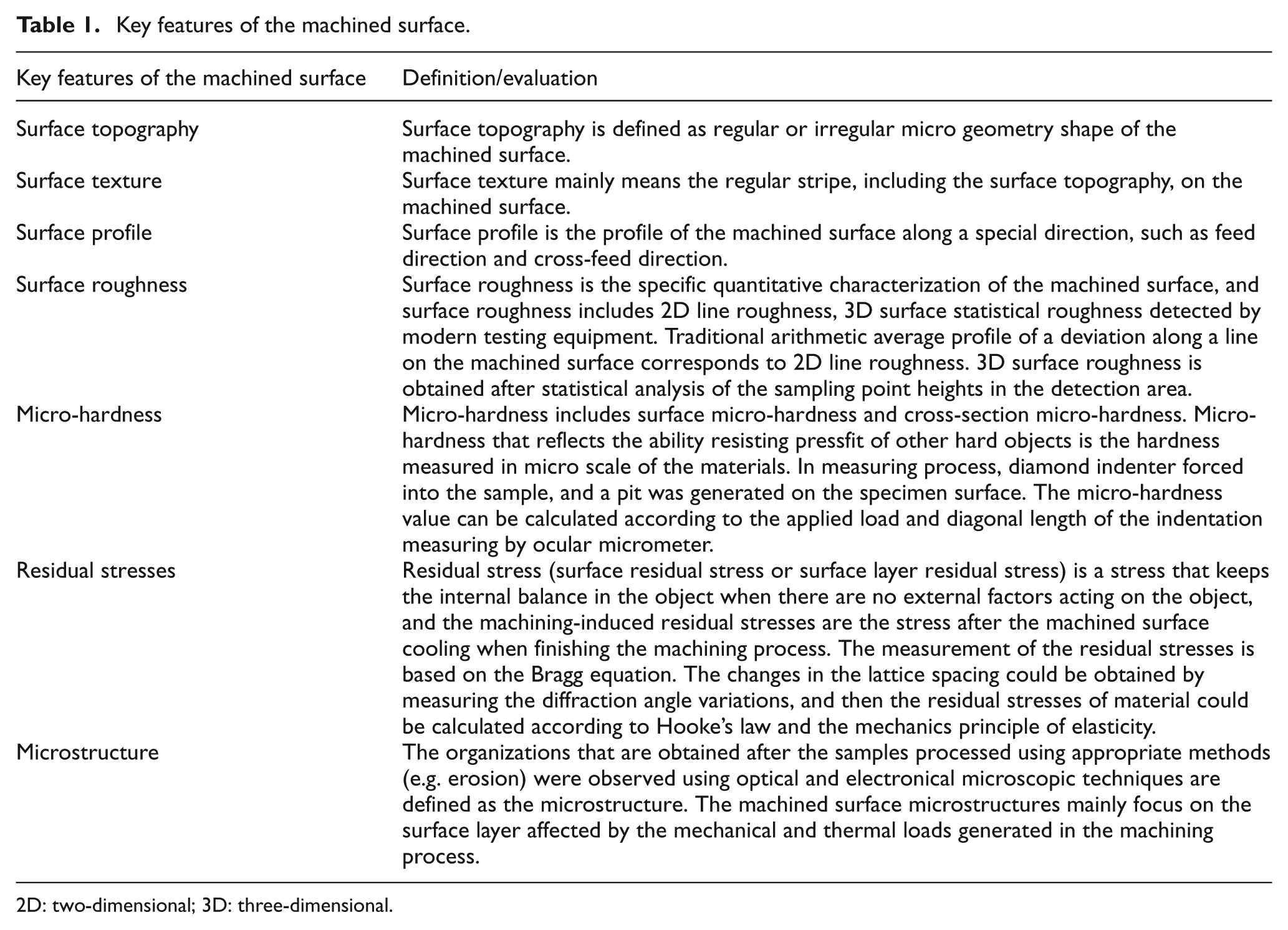
2D: two-dimensional; 3D: three-dimensional.
Milling operation is one of the most commonly used processing methods, and machined surface analysis for various milling processes was largely conducted by many scholars. Table 2 summarizes the research about the characteristics of machined surfaces produced by different types of machining operations. It is obviously seen that machined surface analysis for end milling,1–6,9 face and slab milling,7,8 electrical discharge machining (EDM)9,10 and ball end milling process9,12–17 was largely conducted by many scholars. Investigation on the machined surface generated by ball end milling process was mainly under three-axis machining conditions. A few research works involved the relative inclination angles between the cutter and workpiece by setting the workpiece geometry, and furthermore, relative inclination angles were limited.
Research about the characteristics of machined surfaces produced by different types of machining operations.

EDM: electrical discharge machining; 2D: two-dimensional; 3D: three-dimensional.
Toh 11 investigated the surface topography and texture when high-speed milling inclined hardened steel workpiece with inclination of 75° under various cutter paths, and three-dimensional (3D) topography together with two-dimensional (2D) profile of the machined surface is discussed. Daymi et al. 5 investigated the surface roughness, residual stress, micro-hardness variation and the microstructure under various cutting speeds, feeds and depth of cut with regard to end milling process with TiAlN-coated carbide tool, and workpiece inclination angles were also considered as a variable factor in the cutting experiments. Axinte and Dewes 12 focused on the effects of cutting speed, workpiece angle, feed rate on the surface roughness, machined surface micro-hardness, residual stresses and microstructure variation using the two-level full factorial experiments employing ball end nose mill coated with TiAlN. Mhamdi et al. 13 investigated the influence of tool position and other related cutting parameters on the surface topography and roughness, micro-hardness and microstructure of the machined surface generated by the ball end milling of concave surface, and the experiments were carried out on a three-axis machine tool. Liu and Loftus 14 investigated the prediction of surface topography for ball end milling process. Jawahir et al. 9 studied experimental techniques, such as Raman spectroscopy, acoustic methods and scanning acoustic microscopy, and so on, to measure various evaluation parameters of surface integrity, and turning, milling, grinding and EDM machining operation were incorporated in the authors’ research work, while the milling process was mainly for general milling such as face milling and end milling, and few works about the multi-axis milling process were presented. Sriyotha et al. 15 developed a comprehensive simulation system for predicting the surface topography and roughness formed in the milling process, and the effects of machining parameters were studied. Aspinwall et al. 16 investigated the effects of tool orientation and workpiece inclination angles on workpiece surface roughness (Ra), subsurface microstructure/micro-hardness and residual stress when machining Inconel 718 under finish cutting condition. It is shown that the horizontal downward cutter orientation could provide preferred surface roughness, cutting forces and tool life, and workpiece inclination angle 0° leads to the highest levels of compressive residual stress. Nevertheless, the works involving the relative inclination angles between tool and workpiece are achieved by setting the special workpiece geometry, and the relative postures between tool and workpiece are only equivalent to employment of a single tilt or lead angle in multi-axis machining operation. The tool inclination angle combinations were not studied in the related works.5,11–13,16
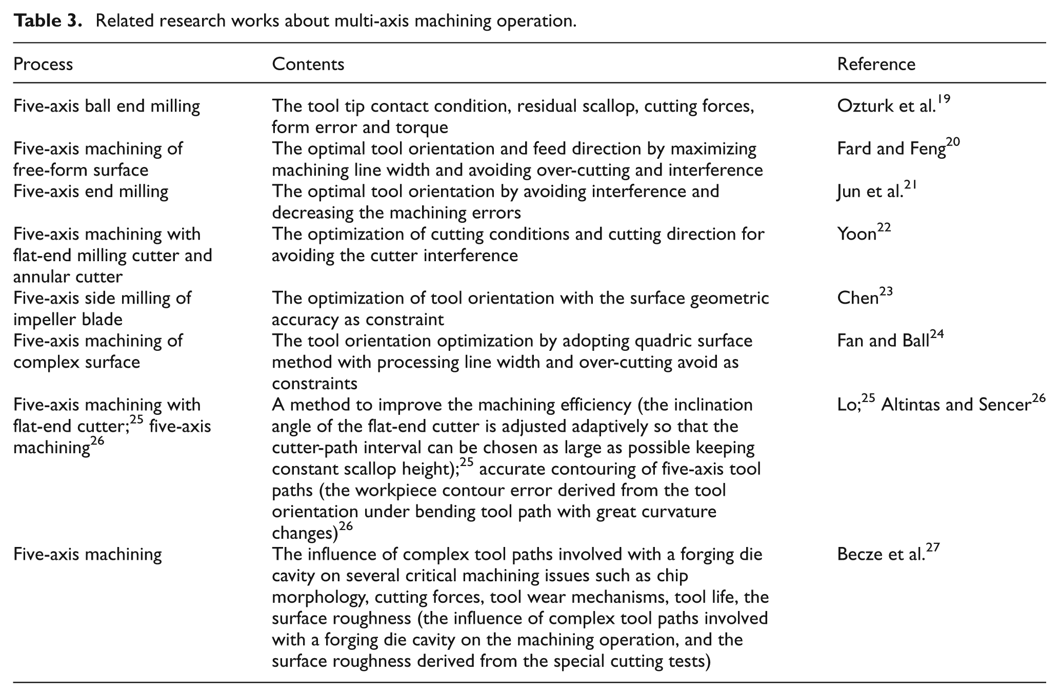
Tool orientation is the key factor greatly affecting the machined surface integrity. At present, researches related to the tool posture mainly focus on the effects of tool orientation on the machining process, avoid interference, and tool orientation optimization for enhancing the machining precision. Table 3 shows the related research works about five-axis machining operation, and most of the works19–26 were about the influence of tool orientation on the machining operation, the optimal control of tool inclination angles avoiding over-cutting and interference, the tool orientation optimization with the machining accuracy as the constraint and so on. From the analysis of both Tables 2 and 3, it could be seen that few works17,18,27 concentrated on or involved the effects of process parameters, especially the tool orientation, on the surface integrity of multi-axis machining operation.
Related research works about multi-axis machining operation.
Denkena et al. 17 studied the ball end milling of TiAl6V4 in which the lead angle of 15° was used, and the kinematic and stochastic features of the surface topography together with surface roughness were analyzed. Becze et al. 27 investigated the influence of complex tool paths involved with a forging die cavity on the machining operation (such as chip morphology, cutting forces, tool wear mechanisms and tool life), and a little attention was paid on the surface roughness derived from the special cutting tests. Kalvoda and Hwang 18 mainly studied the influence of different tool orientations (tilt and lead angles of 0°, −15°, −30°, 15° and 30°), coolant usage or not and depth of cut on the surface integrity (surface residual stresses, micro-hardness variations, surface roughness and texture), and the results adopting several inclination angles showed that tilt angel caused compressive residual stress. It is also concluded that the magnitude of the residual stresses are not affected by the depth of cut, while use of coolant does affect the magnitude of the residual stress. However, the tool inclination angle combinations were not considered in the related studies concentrating on the multi-axis machining operation.17,18
Although plenty of attention has been focused on the machined surface integrity generated by the various milling operations including ball end milling, few systematic and effective works were concentrated on the machined surface integrity with regard to the multi-axis milling process using ball end mill cutters with different tool inclination angle combinations. Hence, this work mainly focused on the surface topography, surface texture, roughness, hardness of the machined surfaced layer and machined surface residual stresses generated by the high-speed milling with various inclination angle combinations in multi-axis ball end milling process. Ball end milling process with tool inclination angles is widely used in the machining of the products with complex surface features, and the reports of this research work would greatly deepen the understanding of the multi-axis ball end milling process, which is also beneficial to the process parameter optimization.
Geometrical analysis and experimental settings
The CAD/CAM packages UG NX were applied to implement the geometrical analysis of the contact zone of the tool and workpiece. The five-axis machining center DMU 70V DECKEL MAHO was used in the milling experiments. H13 die steel is the material to be cut, and the two-flute solid carbide ball end mill (model: 111100-MEGA-64) with diameter of 10 mm was selected as the cutting tool. The optical profiler (model: Veeco NT9300), X3000 stress analyzer (Xstress 3000), HL-600 Leeb hardness tester and micro-hardness tester (model: 401MVA) were employed to collect the machined surface information.
Eight types of inclination angle combinations could comprehensively incorporate all cutting conditions with various tool inclination angles under up-milling condition, and so this work adopts the geometrical analysis method to set the tool rotation angle which directly leads to special inclination angle combination. The intersection angle between the tool axis and normal direction of the machined surface was first fixed at a special angle, and then we determine the tool orientation by rotating tool axis around the normal direction of the machined surface to incorporate the whole tool orientations. The corresponding inclination angles (tilt and lead) under special tool rotation angle could be calculated according to the specific geometric equations, and the calculated inclination angles (tilt and lead) were entered into the CAM software (UG NX 4.0) to generate the tool path and NC program. Finally, the NC codes derived from the corresponding post processor, which was built according to the machine tool structure and motion characteristics, were used to carry out the experiments. Finally, the machined surface under these tool inclination angle combinations could be investigated to get better understanding of the generation of the machined surface and to provide support for process parameter planning.
The surface topography and surface roughness of the machined surface appearing in this research were measured with the optical profiler (model: Veeco NT9300). The optical path difference is measured by using the theory of optical interference, and then the related physical quantities could be determined, and the data collected by the optical profiler were introduced to a computer to plot 2D profiles and 3D surface topographies of the machined surface. Residual stresses were measured by Xstress 3000 test system, and the system mainly consist of portable host, logic controller, angular instrument and so on. Two systematic detectors record diffraction information from two opposite directions, and each detector independently employs cross-correlation method to determine the diffraction peak. The structural design could avoid the impact of asymmetry error and random error induced by the absorption correction and Lorentz correction, and measurement error of stress-free iron powder can be controlled within ±8 MPa. Based on the Bragg law, the deterministic relation among the X-ray wavelength, interplanar crystal spacing and diffraction angle could be determined, and then the relationship between micro interplanar crystal spacing and macroscopic measurable diffraction angle could be established. Furthermore, interplanar crystal spacing could reflect the stress state of the corresponding measured zone. Finally, the residual stresses can be obtained. The calibration using stress-free iron powder, which was used to determine the distance between the collimator and the specimen surface, was conducted before the formal measurement operation. In order to make equipment thermal stability, at least five times measurement should be performed before calibration.
In order to investigate the cross section of the machined surface under various cutting parameters, the samples corresponding to various experimental parameters shown in Table 4 were prepared. The samples used for the test of cross section for the machined surface layers generated by finishing milling process were processed by lapping and polishing. The abrasive material used in lapping process was boron carbide power, and the diamond polishes were used in polishing operation. The surface hardness with the unit of HL was measured using HL-600 Leeb hardness tester and was evaluated by the velocity of the detector going toward and the velocity getting back from the surface. The micro-hardness tester (model: 401MVA) was used to measure the micro-hardness of the top machined surface and the cross section of the samples, and the micro-hardness values were evaluated by the indentation size. The final measured data were obtained in the forms of average of three measured values.
Detailed settings of cutting parameters and tool rotation employed in the ball end milling experiments.
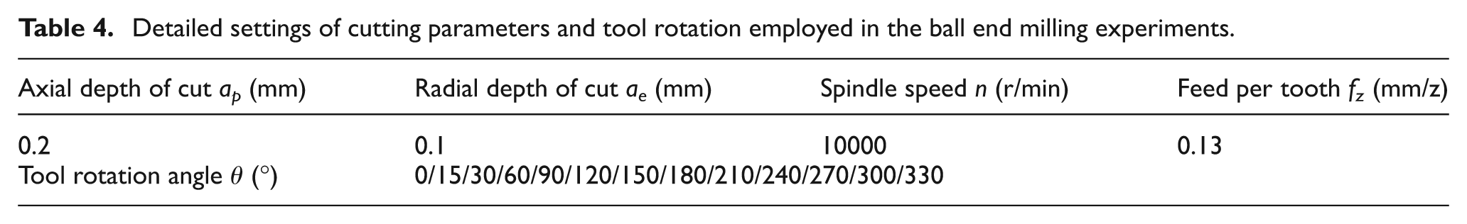
Experimental parameters are shown in Table 4, and the tool rotation angle could be transferred into the corresponding combinations of tilt and lead angles. In this research, the intersection angle between the tool axis and the normal direction of the current machined point on the workpiece is fixed at 25°. The experiments were carried out under up-milling condition for all cutting parameters.
The schematic diagram for the processing parameters is shown in Figure 1. Figure 1(a) shows the diagram for transforming rotation angle around the normal direction to the inclination angle combination, and diagram for definition of eight different types of inclination angle combinations is shown in Figure 1(b).
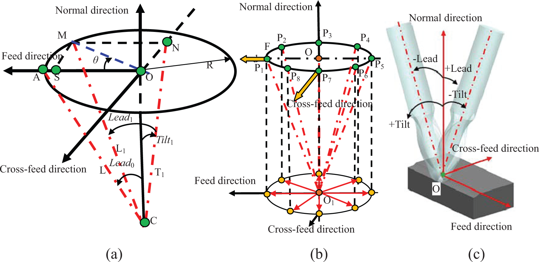
Schematic diagram of the tool axis rotating around the normal direction: (a) diagram for rotation angle transformation, (b) diagram of tool axis projection and (c) diagram of tilt and lead.
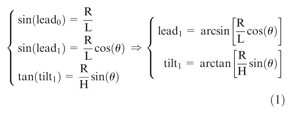
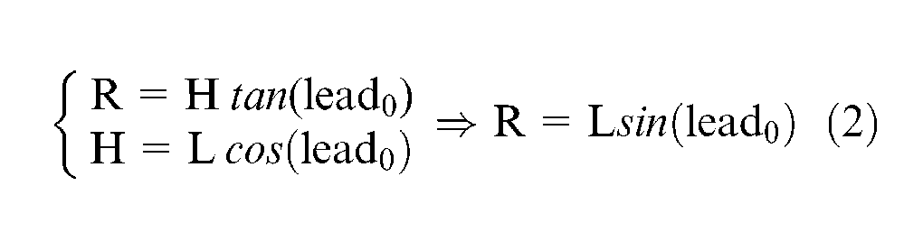
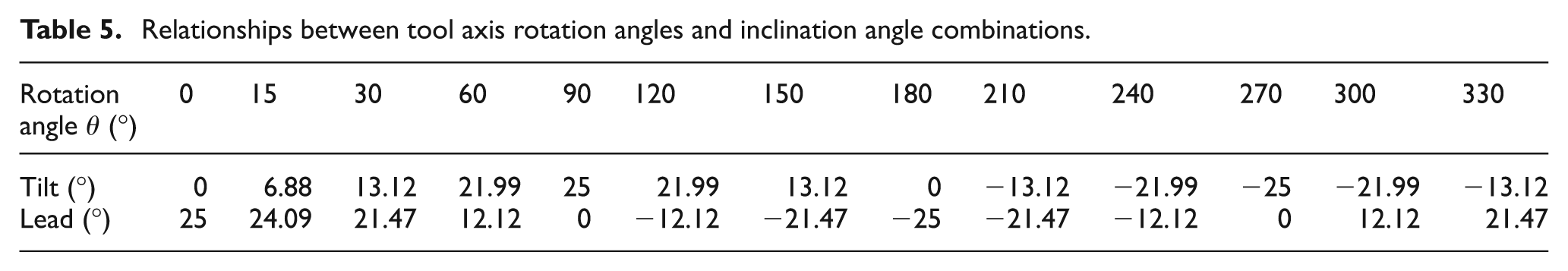
In Figure 1(a), the point C represents the ball center of the spherical part in the cutter, and CO is the normal direction of the current cutting point. T1 (CN) is the tool axis after rotating the tool axis without inclination angles around feed direction with the rotation angle tilt1, and L1 (CM) represents the tool axis after axis T1 (CN) rotating lead1 about the cross-feed direction. CA (tool axis L) is the initial tool axis with only positive lead angle. R is the radius determined by the intersection angle between the tool axis and the normal direction with the variations of tool axis rotation angles. The symbol θ is the tool axis rotation angle about the normal direction with the tool axis CA as the initial measuring standard. H is the distance between the points C and O. MN is perpendicular to the cross-feed direction, and MS is perpendicular to the feed direction. L is the length of the tool axis. Tilt and lead angles corresponding to the tool axis rotation angles could be calculated according to equations (1) and (2), and the calculation results of tilt and lead angles under the corresponding rotation angles are shown in Table 5. The rotation angle of 15° was added between 0° and 30°, while the other rotation angles are determined with the 30° as the incremental interval. The value of lead is equal to 25° as the initial posture for transforming tool rotation angles to inclination angles
Relationships between tool axis rotation angles and inclination angle combinations.
The term “inclination angle” means the tilt and lead angles of the tool used in the multi-axis milling process, as shown in Figure 1(c). The tilt angle is the angle of the tool axis rotating around the feed direction, and the lead angle is the angle of the tool axis rotating around the cross-feed direction. The positive or negative values of the tilt and lead angles are determined by the right-handed screw rule, and the angles toward counterclockwise are determined as positive values when looking from the positive direction of feed and cross-feed direction corresponding to tilt and lead angles, respectively. Feed direction is the direction of forward motion of the tool along the tool path, while cross-feed direction, which is perpendicular to the feed direction, is the moving direction of the tool when transferring between the adjacent tool paths.
Analysis of the machining characteristics of the various cutting conditions
The 13 tool axis rotation angles shown in Tables 4 and 5 corresponds to 13 different inclination angle combinations, and all the inclination angle combinations could be divided into 8 different types. Eight different types of tool inclination angle combinations are determined through the diagrammatic drawing shown in Figure 2. The upper-left part of Figure 2 shows the 3D diagram for the various inclination angle combinations, and the upper-right part is the planar projection along the normal direction of the current cutting point. The projection of tool handle end is ellipse, and the number from 1 to 8 represents the eight different types of inclination angle combinations. So the confirmation of different types of inclination angle combinations can be determined according to the position of the tool handle end projection, which is similar to the definition of quadrant in mathematics shown in the upper-right part of Figure 2. The axes with special direction are defined based on the feed and cross-feed direction in practical machining operation. The intersection between the two axes is the origin of the quadrant diagram. The definition of eight types of inclination angle combinations are based on the standard of clockwise rotation around the origin of the quadrant diagram, which is opposite to the conventional criteria for the definition order of quadrants.
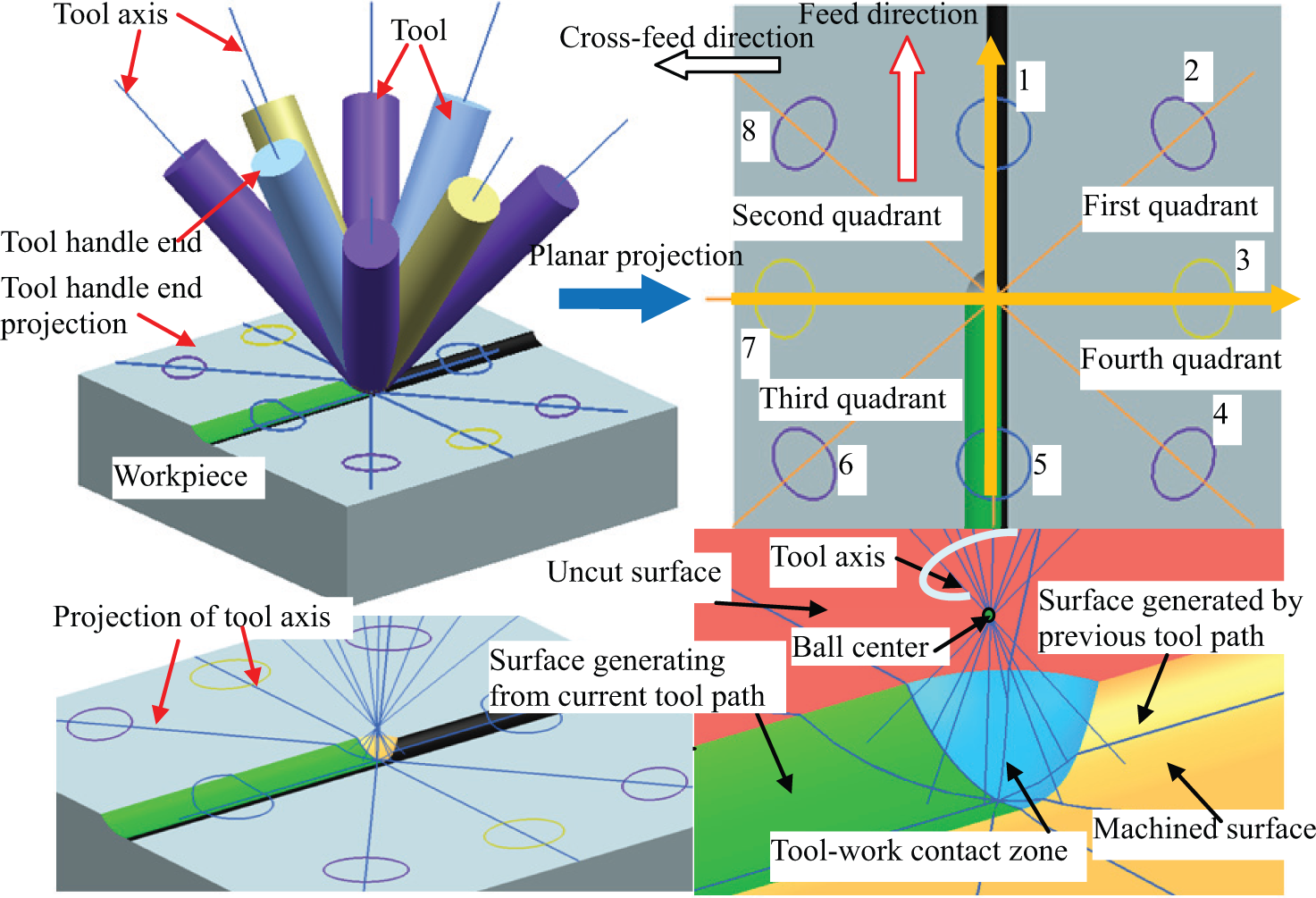
Sketch map for eight types of inclination angle combinations.
In the lower-right part of Figure 2, it can be seen that the action zone between tool and workpiece is determined from the uncut surface on the workpiece, machined surface, surface generating from the current tool path and the previous tool path. According to the tool axis distribution, the tool tip positions under different inclination angles are also different from each other in the practical cutting process.
Figure 3 shows the projection drawings along the normal direction with regard to the eight different types derived from different combinations of tilt and lead angles, and the number represents the inclination angle combination corresponding to the projection number shown in the upper-right part of Figure 2. The tool orientations relative to the workpiece are obviously different from each other, as shown in Figure 3, and the action mode and cutting characteristic of the engaged cutting edges under different inclination angle combinations are also different. The detailed analysis of the machining characteristics of each inclination angle combination is discussed as below.
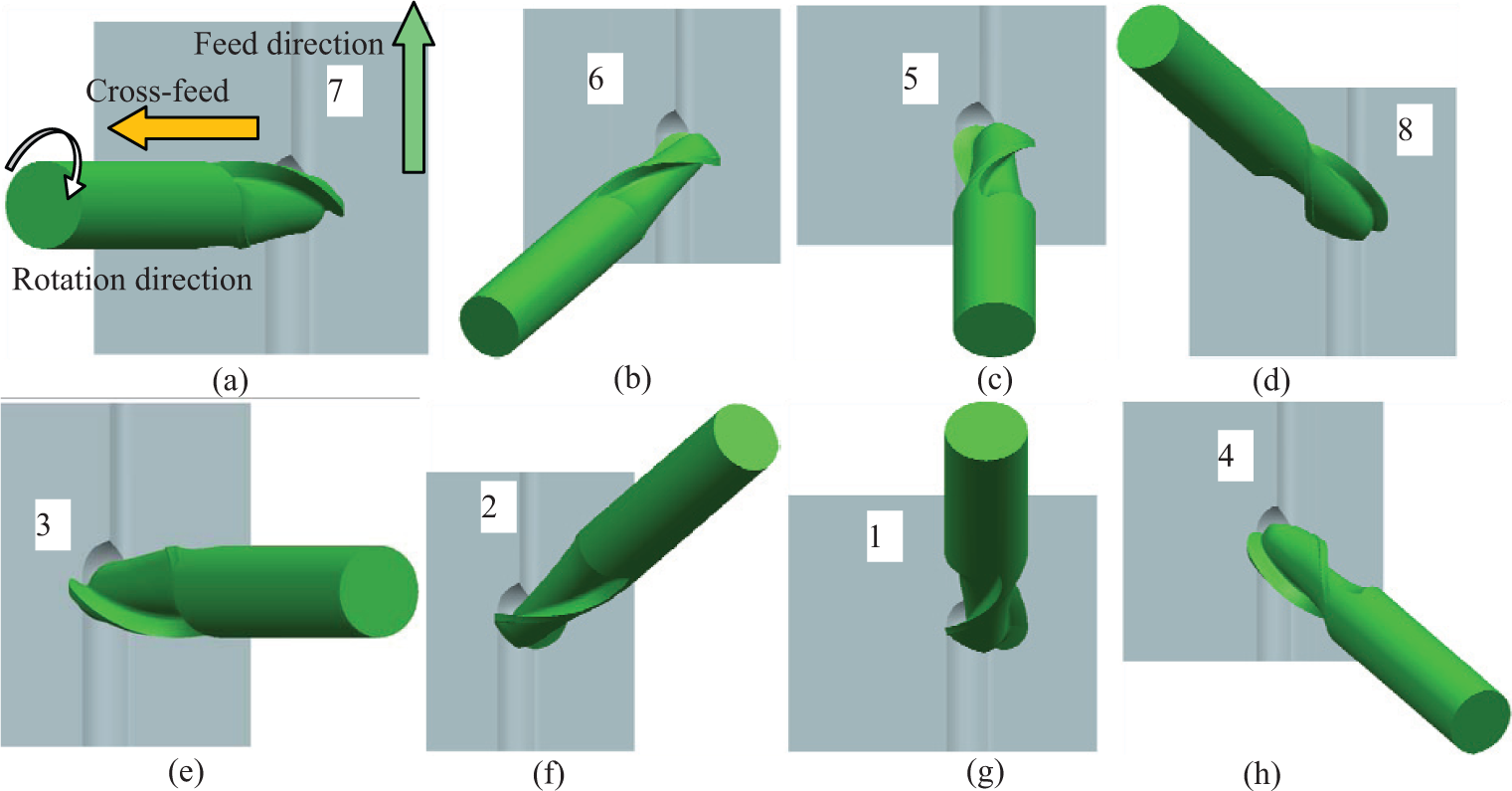
Vertical views corresponding to eight different types of inclination angles combinations: (a) negative tilt, (b) negative tilt and negative lead, (c) negative lead, (d) negative tilt and positive lead, (e) positive tilt, (f) positive tilt and positive lead, (g) positive lead and (h) positive tilt and negative lead.
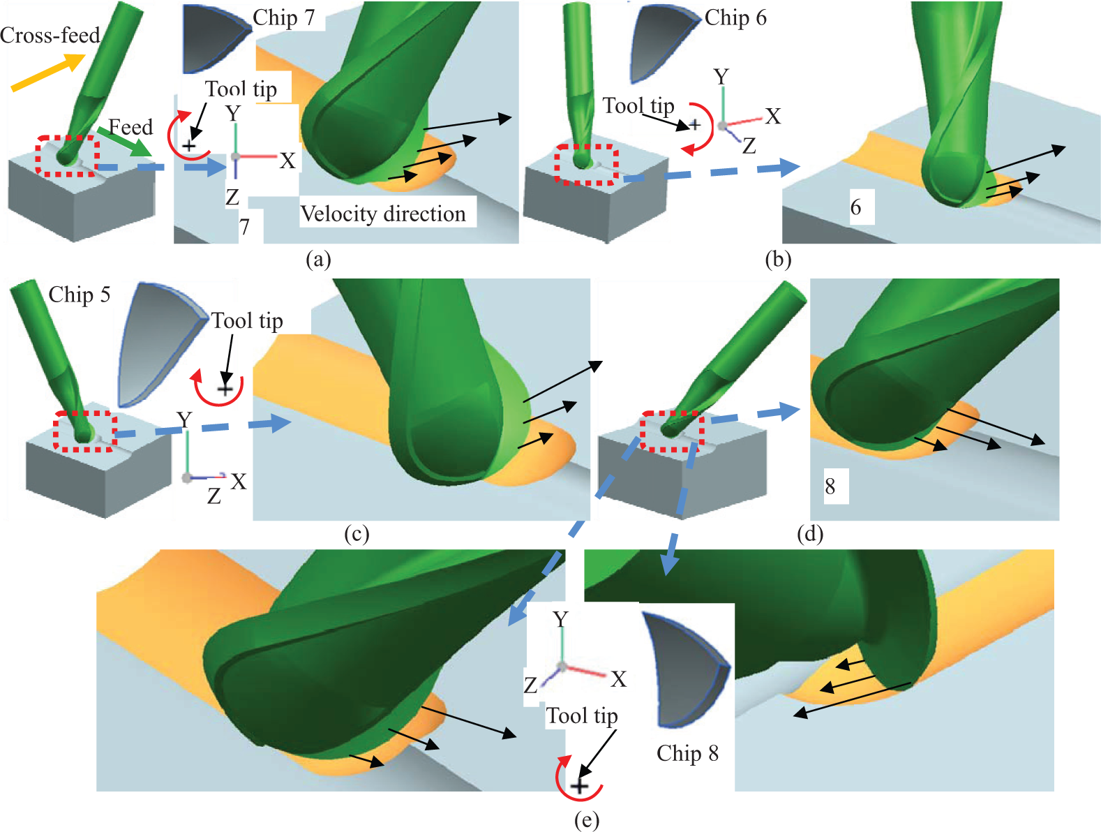
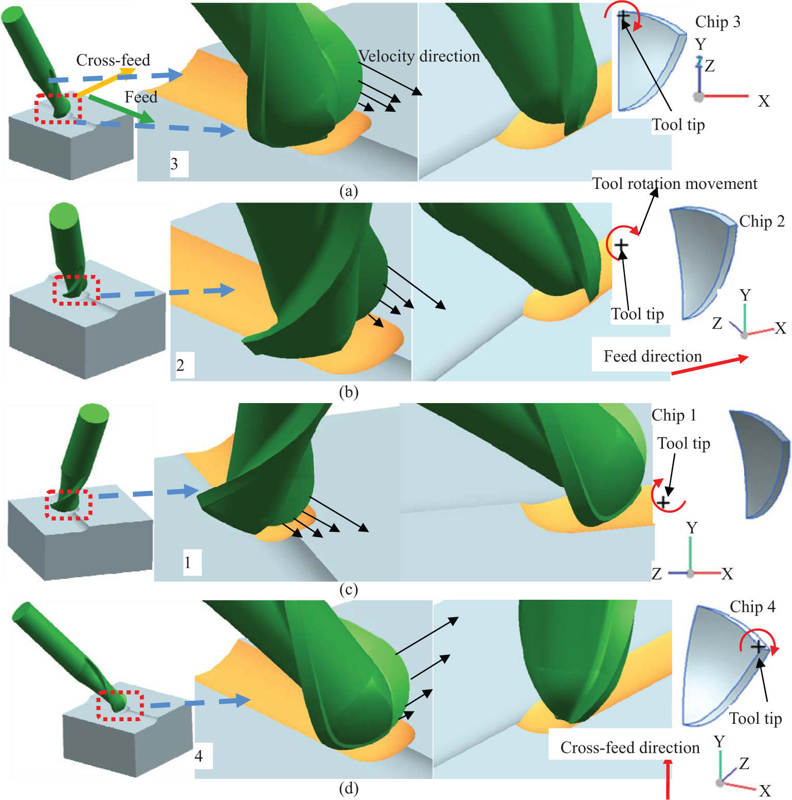
The 3D geometry model of the ball end mill and the configurations for the engaged cutting edges near the tool–workpiece contact zone under eight different types are shown in Figures 4 and 5. The number of each subgraph corresponding to the eight different types is shown in Figures 2 and 3. Through the analysis of the enlarged views for each type, the effective cutting speed of the engaged cutting edges, variation of in-process chip thickness, space for chip eliminating away from the workpiece and the condition of whether the tool tip participates in cutting or not are different for the various cutting conditions with special inclination angle combinations. According to the chip geometry and the relative chip position to the tool tip, the variations of the chip thickness corresponding to different inclination angle combinations could be concluded with the tool rotation movement in one special cutting condition. The coordinate system OXYZ of 3D chip is also presented for each type with special inclination angle combination. The X axis is parallel to the feed direction, and Y axis is parallel to the cross-feed direction.
Geometrical diagram for various inclination angles combinations from type 1 to type 4: (a) negative tilt, (b) negative tilt and negative lead, (c) negative lead, (d) negative tilt and positive lead and (e) partial enlarged drawings from different views for condition of negative tilt and positive lead.
Geometrical diagram for various inclination angles combinations from type 5 to type 8: (a) positive tilt, (b) positive tilt and positive lead, (c) positive lead and (d) positive tilt and negative lead.
Considering the types with regard to the inclination angle combinations with negative tilt angle, such as the condition shown in Figure 4(a), (b) and (d), the tool tip of the cutter locates in the position away from the tool–workpiece contact zone, and the effective engaged cutting edges result in high effective cutting speed. Moreover, the thickness of in-process chip varies from thin to thick, and the chip thickness becomes thin in the last stage. In Figure 4(c), the space for chip eliminating away from the workpiece is large and beneficial to chip removal corresponding to the type with negative lead angle, while the relative posture between the cutter and the workpiece with positive lead angle shown in Figure 4(d) and (e) may lead to the difficulty in chip removal from the workpiece. The velocity direction of the engaged cutting elements that is presented in the forms of arrows would directly affect the material removing mode and the impact of the engaged cutting edges on the workpiece. The upward pull effect of the engaged cutting edges probably appear corresponding to the type with combinations of negative tilt and negative lead angle shown in Figure 4(a)–(c), while the downward extrusion action may exist under the type with positive lead angle shown in Figure 4(d) and (e).
Considering the types shown in Figure 5, the tool tip may probably participate in the cutting process under the cutting condition with positive tilt angle shown in Figure 5(a) and (d), while the tool tip does not engage in cutting process when positive lead angle exists in the inclination angle combinations, such as the condition shown in Figure 5(b) and (c). It can be observed that the tool tip moves away from the tool–workpiece contact zone when lead angle is positive after the tool owning positive tilt angle, as is shown in Figure 5(b). The effective cutting speed of the engaged cutting edges is relatively lower for the four types shown in Figure 5(a)–(d). The in-process chip thickness is in the state of thickening, and then become thin in the follow-up stage of formation process under the types shown in Figure 5(a) and (b). The chip thickness corresponding to the types shown in Figure 5(c) and (d) changes from thin to thick in the initial cutting stage, and then changes from thick to thin in the last cutting stage because of posture and movement of the engaged cutting edges under special cutting condition. Generally, the chip thickness changes from thin to thick, and then it becomes thin. However, the proportion of the each stage with different variation trend is different from each other, which directly affects the cutting process and the machining results.
Results and discussions
Surface topography and roughness
In order to avoid the effects of oxidation layer of the uncut blank on the machining operation, end milling of the blank was first conducted before the formal cutting experiments, and three-flute end mill with diameter of 10 mm and radius of 0.2 mm (model: 910100R020-TRIBON) was used. End milling process was under up-milling condition, and the depth of cut, width of cut, cutting velocity, and feed per tooth were 0.3 mm, 2 mm, 158 m/min and 0.19 mm/z, respectively. The surface topography, texture and roughness under two different magnification factors are shown in Figure 6(a) and (b). The surface topography and surface roughness of the machined surface were measured with the optical profiler (model: Veeco NT9300).
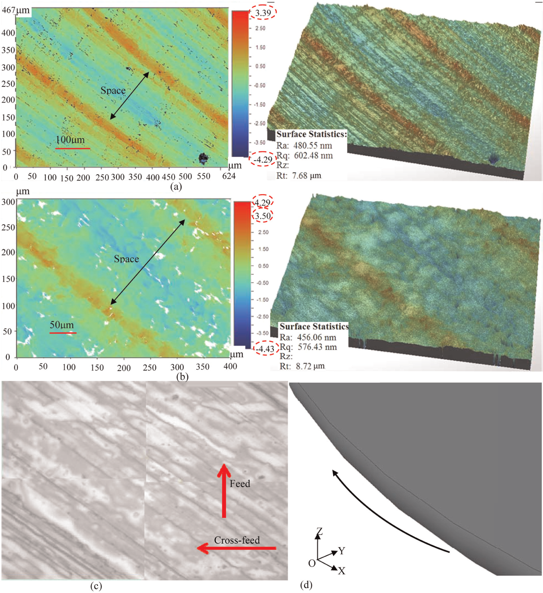
Surface topography after the rough end milling: (a) topography and corresponding roughness, (b) enlarged view of topography and corresponding roughness, (c) surface texture and (d) diagram of the tool end radius and motion.
The round off part of the cutting part end engaged with the workpiece in the combined movement form of linear feed and rotary motion, which would results in the cambered marks in the machined surface. The space between the two adjacent machining marks is closely related with the feed distance under one full tool revolution. The height of the machining marks are determined by the depth of cut, and the depth of the valley features in the machined surface is very closely related with the machining vibration in the cutting process which leads to the tool axial run-out.
Surface topography under changing tool orientation
In practical machining, the effective velocity direction of engaged cutting edges which would directly affect the surface texture after machining operation can be represented by the velocity direction of the lowest contact point of the cutter engaging in cutting, and so the grain direction evaluated by the intersection angle between the effective velocity direction and the feed direction can be demonstrated.
Figure 7 shows the variations of surface texture with the increment of tool rotation around the normal direction. Together with grain direction determined by the effective velocity direction, the variations of surface texture can be better explained. The phenomenon of grain direction keeping parallel with the cutting speed direction was also found in the three-axis end milling process, 1 while the grain direction in multi-axis ball end milling varies under different inclination angle combinations in this research. The interval between the adjacent traces is determined by the feed per tooth in microcosmic perspective. In the case of smaller depth of cut and width of cut, generation of smaller scallop height after machining operation occurs, and the cutting speed direction for the lowest point in the engaged cutting edge that is closer to the machined surface through the whole cutting process determines the final grain direction.
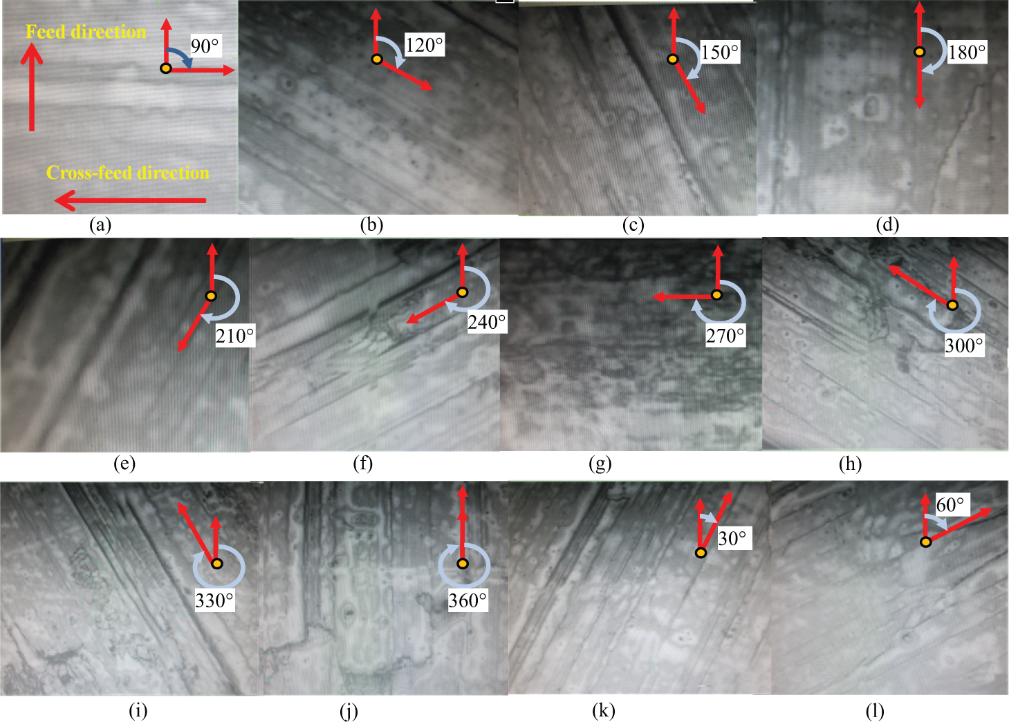
Surface textures under different rotation angles: (a) 0°, (b) 30°, (c) 60°, (d) 90°, (e) 120°, (f) 150°, (g) 180°, (h) 210°, (i) 240°, (j) 270°, (k) 300° and (l) 330°.
Also, some other geometrical features could be seen through Figure 7, such as micro scallops, spot corrosion, irregular residual traces and so on. Figure 8 shows the enlarged views of the surface textures for the conditions with some special rotation angles, such as 15°, 150°, 300° and 330°. The scallops could be obviously seen in subview of Figure 8(a), (d) and (e), especially in Figure 8(e). The irregular residual traces could be seen in Figure 8(b) under rotation angle of 300° corresponding to the negative tilt angle with larger value and the positive lead angle with smaller value, and the detailed cutting condition of which is shown in Figure 4(d) and (e). In the chip formation process for this type, the in-process chip thickness gradually increases, and the engaged part in the cutting flute which acquires the motivation of pressing downward toward the final formed surface is close to the final formed surface at the initial stage. As a result, the irregular flow behavior of the material would occur in the formation process of chip and machined surface, and the irregular machining traces appear in the end.
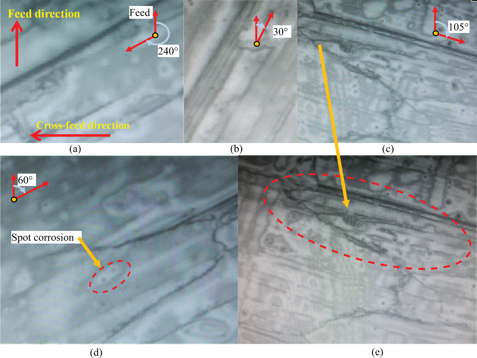
Surface textures under rotation 15° and enlarged view for some other conditions: enlarged view for rotation angles of (a) 150°, (b) 300°, (c) 15°, (d) 330° and (e) local view for rotation angle of 15°
The inclination angle combination in Figure 5(b) corresponds to the condition under rotation angle of 15°, and the tool tip probably engage in cutting with the workpiece. In this special cutting condition, both the downward extrusion effect of one flute and the effect of pulling up the material upward with regard to the other flute exist, and furthermore, the severe extrusion action and scraping effect on the machined surface may probably lead to the generation of obvious sag features.
Figure 9 shows the surface topography and surface texture under rotation angle of 180°, and the detailed surface information under two different amplification factors are presented. The arithmetical mean deviation of the profile of the machined surface is marked as Ra. Surface roughness indicator Rq is calculated based on the root-mean-squared equation, and Rt is the value of peak to valley in the measured scope of the machined surface.
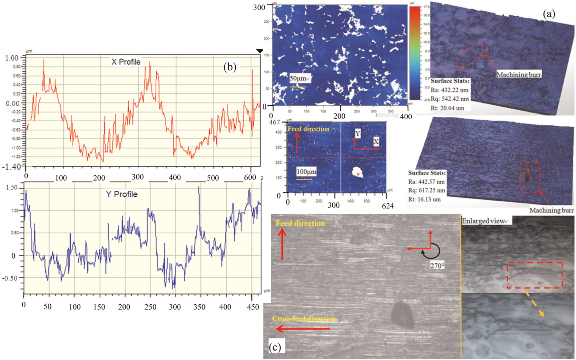
Comparison of the surface topography and texture under tilt 0° and lead −25° when rotation angle is 180°: (a) surface topography under two different amplification factors, (b) surface profile along two lines shown in bottom left of subgraph (a), and (c) surface texture under two different amplification factors.
Figure 9(a) shows the surface topography views under the two different amplification factors, and the measured results are directly related with the measured scope on the machined surface. The measured values corresponding to Ra, Rq and Rt under the two different objectives with different magnification are similar. It can be seen that the sunk pits appear in a high frequency, and the variation of amplitude on the machined surface in the height direction is approximately 20 µm. The value of Rt is larger than the ones under other rotation angles, which is due to the generation of machining burrs under this cutting condition shown in Figure 4(c). The tool tip engaged in cutting process under rotation angle of 180°, and the effective cutting speed direction of the engaged parts in the corresponding cutting flute resulting in the drawing effect makes the in-process chip away from the surface. Also, the effective cutting speed of the engaged parts in cutting flute is small, and furthermore, the former phenomenon interacts together with the plastic behavior of the machined material. Based on the combined action of each cutting phenomenon, the machining burrs would easily be generated in the end.
Figure 9(b) shows the surface profile in two mutual vertical lines on the machined surface, as is shown in bottom-left view of Figure 9(a). The indicators of Rp and Rv represent the height of the peak and the depth of the valley along the corresponding measured lines, respectively.
The surface roughness indicators Rq, Ra, Rt, Rp and Rv are approximately 0.5, 0.42, 2.26, 0.96 and −1.3 µm in X direction, as shown in Figure 9(a), and the values of Rq, Ra, Rt, Rp and Rv are 0.44, 0.37, 2.22, 1.52 and −0.7 µm in Y direction. The surface roughness indicators are mainly influenced by the feed per tooth and vibration of the machining system in Y direction, while they are primarily affected by the width of cut, tool eccentric and radial run-out, and tool deformation in X direction. The varying curves shown in Figure 9(b) are based on one special point in the measured zone, and the values of various surface roughness indicators are similar in X and Y directions through the statistical analysis for many points in the measured region. More surface defects, such as sunk pit and spot corrosion phenomenon, could be obviously found under the objective with high magnification, as is shown in the bottom-right view of Figure 9(c).
Surface roughness analysis
The variation of surface roughness with the tool rotation angle in the scope of measurement area is shown in Figure 10(a) and (b). The indicators Ra, Rq and Rt in accordance with the above description are different factors evaluating the surface geometrical features and rough degree. The definition of Ra and Rq demonstrates the measurement results with general characteristic, and certain randomness may probably exist when Rt of the one special measured region was considered. Hence, Ra and Rq are used as the evaluating indicators for the comparison of the surface roughness between the different tool rotation angles, while the indicator Rt is used as auxiliary evaluation index for the surface roughness under various tool rotation angles.
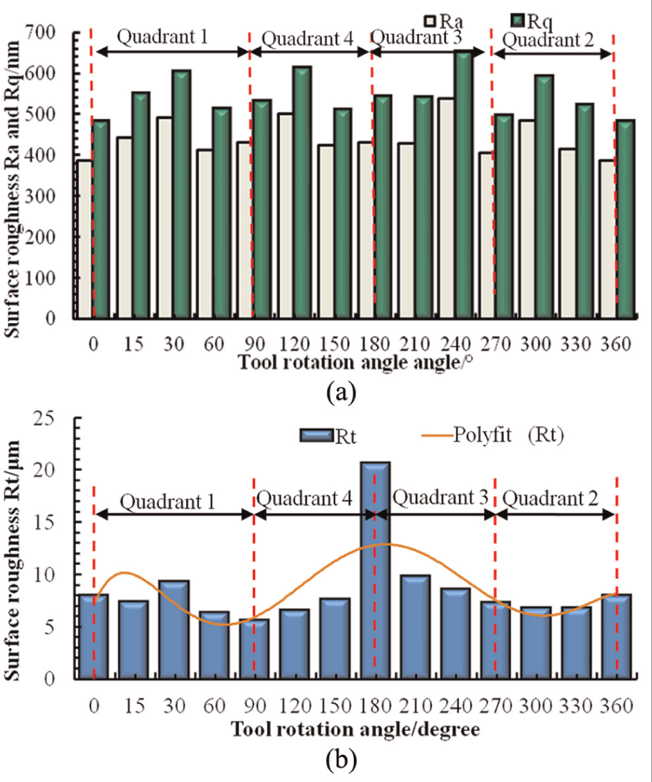
Surface roughness of the machined surface under various rotation angles: (a) surface roughness indicators Ra and Rq of the machined surface and (b) surface roughness indicator Rt of the machined surface.
The smaller surface roughness indicators appear when rotation angles of 0°, 60°, 90° and 330° were used in the finish milling condition. Toh 11 concluded that best workpiece surface texture could be obtained when employing single-direction raster vertical upward orientation with workpiece inclination angle of 75°, which corresponds to the cutting conditions with lead angle of 75°. Daymi et al. 5 also found that workpiece inclination angle of 25° which is equivalent to rotation angle of 0° corresponding to lead angle of 25° in this research work provided the best surface finish because of avoidance of cutting at the tool tip.
The surface roughness under specific process parameters is directly determined by the general cutting parameters (e.g. axial depth of cut, radial depth of cut, feed per tooth, spindle speed and inclination angle combination), and the vibration and cutting forces are the indirect influencing factors. The amplitudes and variation trends of the cutting forces under different inclination angle combinations are different, which is attributed to the different material removal characteristics corresponding to various inclination angle combinations. The machining vibration would lead to the fluctuations of cutting forces, and then the unsteady removing of the chip materials from the workpiece could indirectly result in the variations of the machined surface roughness. Moreover, the cutter deflections induced by the cutting forces are also the key influencing factor on the surface roughness. Pure rigid tool is ideal consideration, while the tool deflection is difficult to be avoided in practical machining operation, and so the tool inclination angle combinations corresponding to the cutting forces that lead to small tool deflection are preferred tool orientation.
Table 6 shows the particular descriptions of the cutting conditions with larger roughness corresponding to the projection of cutter handle end locating within the quadrant. The cutting configurations for rotation angles of 30°, 120°, 240° and 300° are presented in Figures 5(b), (d), 4(b), and (d) and (e), respectively.
Cutting conditions with large roughness value when the projection of cutter handle end is on the quadrant axis.
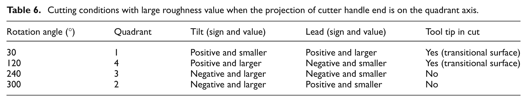
The cutting condition under rotation angle of 240° corresponding to inclination angle combination of negative tilt with larger value and negative lead with smaller value results in the larger surface roughness Ra and Rq. The upward pull effect of the engaged cutting edges would occur when rotation angle is 240°, which may probably be detrimental to the surface roughness improvement. However, the downward extrusion effect of the engaged cutting edges under rotation angle of 300° with negative tilt and positive lead is considered to be beneficial to the improvement of surface roughness. So the surface roughness Ra and Rq under rotation angle of 240° is larger than the those corresponding to rotation angle of 300°.
The values of Ra and Rq under rotation angles of 30°, 120° and 300° are similar. Although the tool tip engages in cutting under rotation angles of 30° and 120°, the tool tip lies on the transitional surface generated during the ball end milling process, and furthermore, the engaged cutting elements on the flutes interacting with the machined surface have high effective cutting speed. Hence, the values for surface roughness indicators Ra and Rq derived from the rotation angles of 30° and 120° are similar with the measured result under condition of rotation angle of 300° without tool tip engagement. The in-process chips under rotation angles of 30°, 240° and 300° present the characteristics of changing from thin to thick, while the variation of chip thickness is from thick to thin in the last chip formation process, which is closely influenced by the engaged cutting edge’s position, posture and mutual movement with the uncut zone.
Table 7 shows the detailed information for the cutting conditions under rotation angles of 0°, 90°, 180° and 270°, and the corresponding cutting configurations are shown in Figures 5(c), (a), 4(c) and (a), respectively. Considering the cutting condition corresponding to the projection of the cutter handle end is on the quadrant axis, the surface roughness Ra and Rq are larger when rotation angles are 180°and 90°, while the values of Ra and Rq are smaller under rotation angles of 0° and 270°. Tool tip engages in cutting process when the rotation angle is 180°, and the engaged cutting edges around the tool tip with low effective cutting speed are very close to the machined surface. The severe extrusion and friction effects would be brought about, and furthermore, material brittleness cannot be very well embodied due to the low effective cutting speed. Finally, the rough surface is produced under this cutting condition. On the condition of rotation angle of 90°, the tool tip also engages in the cutting process, and the tool tip is not close to the machined surface but in the transitional surface generated during the machining operation. The extrusion and friction effects of the cutting edges around the tool tip on the machined surface are not as serious as the former one under rotation angle of 180°. As a result, the surface roughness Ra and Rq corresponding to this cutting condition are slightly smaller than the ones under rotation angle of 180°.
Inclination angles and tool tip position when the projection of cutter handle end is on the quadrant axis.
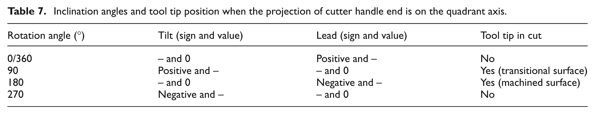
The tool tip does not participate in the cutting process under rotation angles of 0° and 270°, and the effective cutting speed of the engaged cutting edge is relatively large which is beneficial to the improvement of the surface rough conditions. Therefore, the surface roughness indicators Ra and Rq under rotation angles of 0° and 270° are relatively small.
The high value of Rt under rotation angle of 180° is due to the machining burr that is shown in the form of 3D view in Figure 9(a), which is the special individual phenomenon induced by the machining operation.
Investigation of machined surface Leeb hardness and micro-hardness
Surface hardness of the machined surface
The surface hardness with unit of HL was determined by the velocity of the detector working toward the measured surface and the velocity getting back from the measured surface, which belongs to a macroscopic measurement method. The micro-hardness measurement which belongs to the micro measure method was also carried out.
In general, the machined surface hardness has important influence on the surface performance. High surface hardness would lead to high wear resistance performance in an approximate range. However, excessive work hardening may result in the increment of the material brittleness in the surface layer which would decrease the wear resistance performance, and crack generation and metal peeling phenomenon may probably occur.
Kalvoda and Hwang 18 found that the micro-hardness on the machined surface under tool inclination angle of 0° is higher than the one under tool tilt or lead angle of −30° or 30°, which is considered to be the plowing effect during the machining operation with tool tip engaging in the cutting operation. However, the tool inclination angle combination adopted in this work would not directly affect the engagement of tool tip in the cutting zone in close proximity to the final formed surface, and the variations of surface hardness are directly affected by the different cutting characteristics under various tool inclination angle combinations.
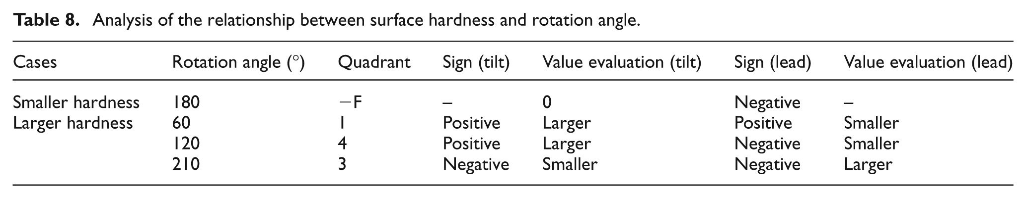
The variations of surface hardness HL and micro-hardness with the rotation angle on the machined surface were shown in Figure 11(a) and (b), respectively. The larger surface micro-hardness values appear when tool rotation angles are equal to 60°, 120° and 210°, while the micro-hardness corresponding to rotation angle of 180° is smaller, which is in accordance with the Leeb hardness measurement result. Combining with the Leeb hardness measurement results in Figure 11(a), the values corresponding to rotation angles of 60°, 120° and 210° are relatively large. In summary, considering evaluation of the surface hardness in both micro and macro views, the rotation angles of 60°, 120° and 210° are the primary choice for obtaining the machined surface with higher hardness, and the finish milling condition with special tool inclination angle combination (tilt 0°, lead −25°) that corresponds to rotation angle of 180° would lead to smaller hardness. Table 8 shows the detailed information, such as the location, sign and value of tilt and lead, for each rotation angle corresponding to smaller hardness and larger hardness.
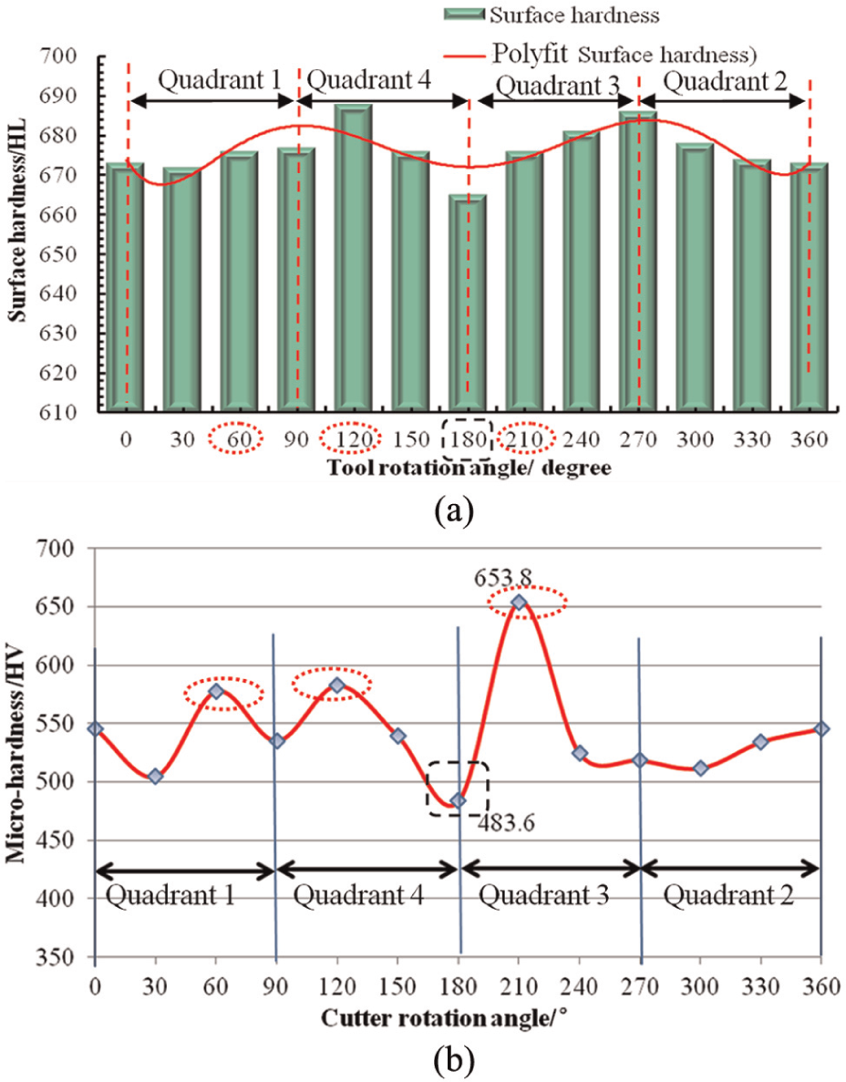
Surface hardness with the increment of rotation angle around the normal direction: (a) Leeb hardness of the machined surface and (b) micro-hardness of the machined surface.
Analysis of the relationship between surface hardness and rotation angle.
Variations of the micro-hardness along the depth direction
Micro-hardness along the depth direction for the measured samples corresponding to each tool rotation angle is shown in Figure 12. The inhomogeneous microstructure distribution of the materials plays an important role in the measured results. The overall variation of the micro-hardness for each rotation angle presents the trend of first decreasing and then increasing with the increase of the depth value. Finally, the micro-hardness value gradually remains stable. Some special points corresponding to larger or smaller micro-hardness values demonstrate the uneven distribution of the raw material microstructure. On the whole, the changing stages of the micro-hardness could be divided into four steps (work hardening layer, abating layer, recovery layer and steady layer), and the diagram is shown in Figure 12(c). In work hardening layer, the micro-hardness is higher than the matrix micro-hardness. In the abating layer, the micro-hardness of the cross section of the sample decreases with the increment of depth value away from the top surface. The micro-hardness in the recovery layer gradually reaches the matrix micro-hardness, and the corresponding micro-hardness remains in a stable state in the steady layer.
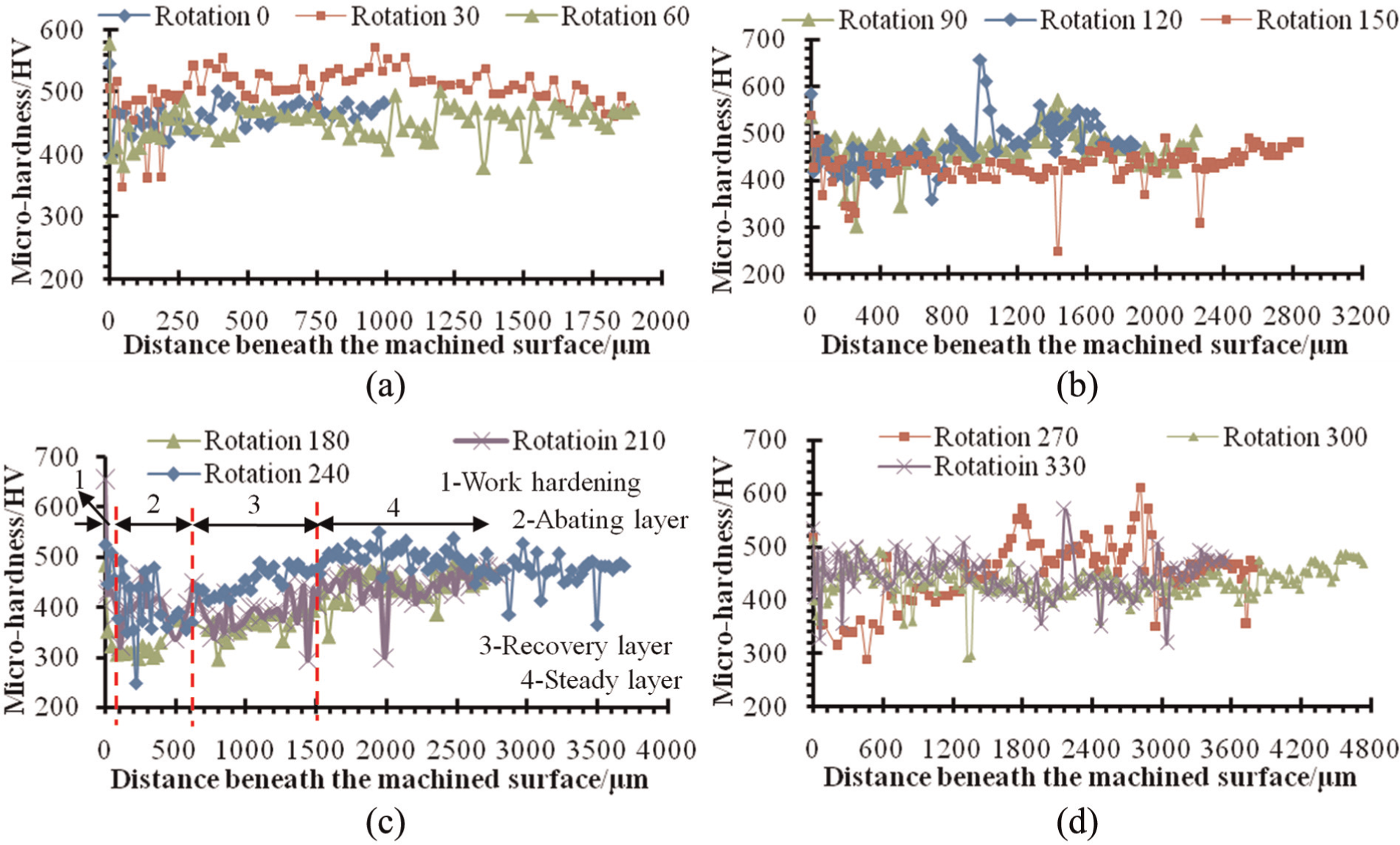
Micro-hardness along the depth direction of the machined surface: (a) micro-hardness when rotation angle is from 0° to 60°, (b) micro-hardness when rotation angle is from 90° to 150°, (c) micro-hardness when rotation angle is from 180° to 240° and (d) micro-hardness when rotation angle is from 270° to 330°.
The top layer of the machined surface was affected by the cutting heat and mechanical load generated in the machining operation, which would probably lead to the appearance of work hardening phenomenon. The cutting heat transferred into the subsurface layer affects the material properties in micro scale, which results in the generation of softening phenomenon to some extent. The thermal and mechanical loads generated in the cutting operation and the action mode of the engaged cutting edges on the tool–workpiece contact zone greatly affect the variations of micro-hardness under each tool rotation angle with different inclination angle combinations shown in Figure 12.
Study of the surface residual stresses corresponding to the various tool orientations
Residual stresses were measured by Xstress 3000 test system, and the system mainly consist of portable host, logic controller, angular instrument and so on. Two systematic detectors record diffraction information from two opposite directions, and each detector independently employs cross-correlation method to determine the diffraction peak. The calibration using stress-free iron powder was conducted before the formal measurement operation. In order to make equipment thermal stability, at least five times measurement should be performed before calibration.
In general, residual stresses in the surface layer induced in machining operation are mainly derived from elastic and plastic of the surface layer material, temperature effects and the change of metallographic structure, and the uneven volume change in surface layer induced by the aforementioned factors would further lead to the generation of residual stresses. The residual stresses both in cross-feed and feed direction under various rotation angles are shown in Figure 13(a) and (b).
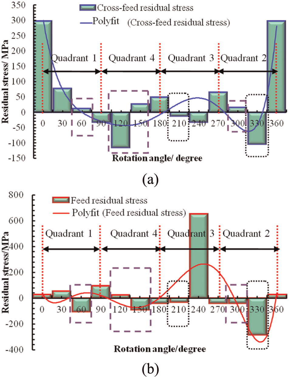
Surface residual stress in cross-feed and feed direction: (a) surface residual stress in cross-feed direction and (b) surface residual stress in feed direction.
It can be seen that compressive residual stresses in both cross-feed and feed directions are generated when tool axis rotation angles are equal to 210° and 330°. The compressive residual stresses in surface layer can prevent generation of the fatigue crack and delay the generation of fatigue failure, which would be beneficial to the antifatigue performance of the components. Furthermore, the tensile residual stress could reduce the corrosion resistance of the parts by generating stress corrosion cracks, while the compressive residual stress could prevent the generation of stress corrosion cracking phenomenon. As a result, the inclination angle combinations corresponding to rotation angles of 210° and 330° would be preferred selections in obtaining compressive stresses in both cross-feed and feed directions on the machined surface in order to improve the surface performance of the machined parts.
The planar projection of the tool handle end is in the third quadrant in the upper-right diagram of Figure 2 when rotation angle is 210°, and negative tilt angle with smaller value and negative lead angle with larger value exist in this kind of tool inclination angle combination which leads to the generation of compressive residual stress in both cross-feed and feed directions of the machined surface. When rotation angle is 330°, the planar projection of the tool handle end is in the second quadrant corresponding to the diagram in Figure 2, and negative tilt angle with smaller value and positive lead angle with larger value are adopted in this kind of cutting condition which results in the generation of expected larger compressive residual stress in general.
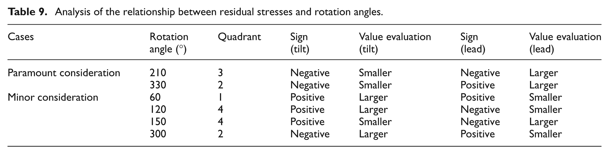
The tool orientations corresponding to the rotation angles resulting in very small tensile residual stress and large compressive residual stress in the two measured directions could also be considered in practical machining operation. The small tensile residual stress in one special direction would not prominently deteriorate the antifatigue performance and corrosion-resistant performance, while the large residual stress in another direction would greatly attribute to the improvement of the machined surface properties. On the whole, the combined effect of the residual stresses in each direction would be beneficial to the enhancement of properties of the machined surface on the components. The conditions under tool rotation angles equal to 60°, 120°, 150° and 300° are also acceptable, and the detailed information, such as quadrant and corresponding inclination angles, are shown in Table 9. In summary, consideration of the appropriate residual stresses being generated, the specific tool rotation angles with the projection of tool handle end locating in each quadrant shown in Figure 2 could be adopted.
Analysis of the relationship between residual stresses and rotation angles.
Conclusion
The multi-axis ball end milling experiments considering different tool inclination angle combinations were conducted. The surface topography, texture, roughness, hardness and micro-hardness of the top surface and cross section of machined surface layer, and surface residual stresses were measured and discussed.
The cutting characteristic of the current flute engaging in cutting apparently varies from each other with the variations of tool orientation. The tool tip locates in the position away from the tool–workpiece contact zone under the cutting conditions adopting inclination angle combinations with negative tilt angle, and the engaged cutting edges result in high effective cutting speed. In the type with negative lead angle of which the upward pull effect is presented, the space for chip eliminating away from the workpiece is beneficial to chip removal. The downward extrusion action of the engaged cutting edges may exist under the type with positive lead angle. Under the type with positive tilt angle, the tool tip may probably participate in the cutting process, while the tool tip does not engage in cutting process when using positive lead angle in the inclination angle combinations.
With a special inclination angle combination, the final grain direction is determined by the cutting speed direction for the lowest point in the engaged cutting edge that is closer to the machined surface through whole cutting process. Some surface defects, such as sunk pit and spot corrosion phenomenon, may probably occur during the machining operation. The downward extrusion effect of the engaged cutting edges under rotation angle of 300° with negative tilt and positive lead is considered to be beneficial to the improvement of surface roughness quality. The upward pull effect of the engaged cutting edges and tool tip engagement may probably be detrimental to the surface roughness improvement.
Considering both Leeb hardness and micro-hardness, the higher surface hardness appears when rotation angles are 60°, 120° and 210°, and the smaller surface hardness appears under rotation angle of 180°. Some special points corresponding to larger or smaller micro-hardness values in the cross section of machined surface demonstrate the uneven distribution of the raw material microstructure. On the whole, the changing stages of the micro-hardness could be divided into four steps (work hardening layer, abating layer, recovery layer and steady layer). The thermal and mechanical loads generated in the cutting operation and the action mode of the engaged cutting edges on the tool–workpiece contact zone greatly affect the variations of micro-hardness under each rotation angle.
Combination of negative tilt angle with smaller value and negative lead angle with larger value when rotation angle is 210° could be adopted to achieve the generation of small compressive residual stress in both cross-feed and feed directions of the machined surface. Inclination angle combinations of negative tilt angle with smaller value and positive lead angle with larger value corresponding to rotation angle of 330° are adopted in this kind of cutting condition which results in the generation of larger compressive residual stress expected. The conditions under tool axis rotation angles equal to 60°, 120°, 150° and 300° are also acceptable to some extent, the values of the tilt and lead angles should be better controlled to achieve the expected results.
Generally, the evaluation indicators of surface integrity are not all very satisfying under one special cutting condition. The process parameter optimization should be determined by the detailed application requirements together with the research results obtained from experiments and model analysis. Under up-milling condition, the negative tilt angle and positive lead angle are prior to select for avoidance of tool tip engagement. The rotation angles of 0° (positive lead), 60° (combination of positive tilt and positive lead), 90°(positive tilt) and 330° (combination of negative tilt and positive lead) are beneficial to the improvement of surface roughness. For high surface hardness, the rotation angles of 60° (combination of positive tilt and positive lead), 120° (positive tilt and negative lead) and 210° (combination of negative tilt and negative lead) are the ideal choices, and the smaller surface hardness appears under rotation of 180° (negative lead). In order to obtain compressive residual stresses on the machined surface, the rotation angle of 330° (combination of negative tilt and positive lead) is the optimum tool orientation, while the rotation angle of 210° corresponding to negative tilt and negative lead is also acceptable. The related cutting parameters are axial depth of cut of 0.2 mm, radial depth of cut of 0.1 mm, spindle speed of 10,000 r/min and feed per tooth of 0.13 mm/z for finish milling condition. In summary, rotation angle of 330° (combination of negative tilt and positive lead) is a preferred tool orientation for comprehensively ideal machined surface integrity.
Looking further ahead, application of the findings of this research work in the machining of free-form surface and demonstration of the machined surface quality will be seriously considered in the future. The microstructure of the machined surface layer generated by multi-axis machining operations is one of the important issues included in surface integrity, and the alteration and evolution of the microstructures induced by special cutting conditions should be investigated in the future.
Footnotes
Appendix 1
Declaration of conflicting interests
The authors declare that there is no conflict of interest.
Funding
This work is supported by the National Basic Research Program of China (2009CB724402).