
Abstract
Traditionally, metal cutting fluid or lubricant is used in finishing operations of high-speed machining process to reduce the rate of tool wear, which in turn will improve surface quality. In automobile and aerospace industries, minimum quantity lubrication technique is considered to provide the same level of performance as the flood coolant method and offers financial benefits by saving coolant direct and associated costs. However, scant research work has been done on minimum quantity lubrication applications in the die and mould manufacturing industry. In this study, the effects of dry, flood and minimum quantity lubrication machining on surface roughness, tool wear, dimensional accuracy and machining time of hardened steel mould inserts were compared. The results revealed that there were no significant differences between these three lubrication methods. More in-depth experimental study of dry and minimum quantity lubrication machining was then carried out using the design of experiments technique. In terms of surface roughness and tool wear, there were again no significant differences. Nevertheless, minimum quantity lubrication machining produced more accurate results than dry machining in dimensional deviation. The regression models show that feed-rate (fz) has a larger effect on surface roughness and machining time than step-over (ae), while depth of cut (ap) has no significant effect on surface roughness. Based on the test piece shape, a shortest possible machining time of 3.55 h and a good surface finish of 0.28 µm can be achieved using a small feed-rate (0.03 mm/tooth), a large step-over (0.1 mm) and a large depth of cut (0.2 mm). This work shows that when combining the minimum quantity lubrication technique with the right cutting conditions in modern die and mould manufacturing, machining time and polishing time can be saved, which leads to an overall saving in production cost. Using the dry and minimum quantity lubrication techniques for different finish machining situations can therefore be a good economical solution.
Introduction
In modern daily life, main commodities are either partially or fully produced in dies and moulds, be it an automobile or an aeroplane, a kitchen plastic container or a drink bottle, a mobile phone or a computer. With the surging demand for these products globally, the die and mould manufacturing industry around the world is facing the tough challenge of having to produce more complex moulds in shorter lead times but with more competitive prices. The complex sculptured surfaces and relatively high material hardness of these intricate moulds have turned modern die and mould manufacturing into an increasingly demanding and difficult engineering task. 1 More than 60% of the total production time of die and mould is spent in manufacturing complex functional components, the machining and polishing operations of which account for approximately two-thirds of the manufacturing costs. 2
The introduction of high-speed machining (HSM) process during the mid-1990s revolutionised die and mould manufacturing practice by reducing the effort for finishing and polishing operations, thereby cutting down the production time. However, the main disadvantage of HSM is tool-life reduction, especially in machining difficult-to-machine materials such as nickel-based alloys, titanium alloys and hardened steels.3,4 Furthermore, the higher cutting speed in turn increases the temperature of the cutting zone, causing accelerated wear of the cutting tool. A traditional way to overcome this problem is the use of cutting fluids, also called coolants or lubricants. The basic functions of cutting fluids are to provide cooling, lubrication and to remove chips from the cutting zone.
Unfortunately, cutting fluid has its own flaws. First, it is expensive. Research studies on machining processes5–7 show that while the cost of the cutting tools is only 2%–8% of the total production expenses, the costs related to the use of cutting fluids range from 7% to 17%. Second, cutting fluids have a negative impact on the health and well-being of the workers. Astakhov 7 reviewed that exposure through skin contact could result in conditions such as dermatitis and folliculitis. Repeated inhalation of coolant mist could also cause decreased lung functions and respiratory diseases, for example, asthma, bronchitis and hypersensitivity pneumonitis. Exposure to some cutting fluids and/or their additives might even cause cancer. In order to reduce the costs of production and to comply with increasingly strict environmental and occupational safety regulations, research and development since the mid-1990s has focused on the total elimination (dry) or huge reduction (near-dry) in cutting fluids. This new manufacturing philosophy was a great advancement in the metal cutting industry. 6 By using advanced cutting tool materials and cutter geometry, dry cutting has been shown to be very successful in certain types of machining processes, such as milling and turning of cast iron.5,6 However, dry cutting fails to produce high dimensional accuracy and good surface finishes in finish machining of hardened steels. Consequently, minimum quantity lubrication (MQL) machining is being considered as an alternative. Machado and Wallbank 8 proved by mathematical calculation that only a small portion of the total amount of cooling lubricant used should be needed to effectively lubricate the tool–chip interface.
HSM of hardened steels in die and mould manufacturing
In modern die and mould manufacturing, the most common machine tool configurations are three-axis horizontal and vertical milling centres. However, the new trend is to utilise simultaneous five-axis milling centres so that complex components can be machined in only one set-up, a process that cannot be achieved by a three-axis machine. The three main advantages of five-axis milling are as follows: the ability to work on all sides of the component in one set-up, the avoidance of tool tip cutting and the use of shorter cutting tools. Studies by Baptista and Simões 9 and Dimitrov and Saxer 10 showed that the simultaneous five-axis machining performed better than the three-axis milling in the following areas: better surface finish, 77% reduction in the total lead-time and an 87% reduction in the overall cost.
As mentioned in previous section, a major drawback of using HSM is tool-life reduction. Finzer 4 and Schulz 11 suggested four different approaches, that is, right cutting tool material, right cutting tool, optimisation of machining parameters and proper machining strategy to tackle this problem. The success of any HSM processes to reduce production time and maintain good surface finish is dependent on the simultaneous implementation of these four approaches. The cutting tool material and optimisation of machining parameters are particularly relevant in the application of dry and MQL machining in HSM.
MQL in HSM
MQL techniques use only a very small amount, ranging from 4 to 50 mL/h, of oil lubricant during the machining process. Compared to the conventional flood coolant method, in which about 20 L/min are consumed, the difference is 24,000–300,000 fold. The basic mechanism of MQL is mixing air and oil lubricant into an aerosol by an atomisation (Venturi) process, with droplets in the size of 1–5 µm. The aerosol mixture can be supplied to the cutting zone via either an external or internal supply system. Each of these systems has proven to be suitable for individual areas of application. 6 Traditionally, in the finishing operation of die and mould cavities and cores, coolants/lubricants are mostly supplied externally via nozzles to the cutting zone. The results from various studies12–15 indicated that supply air pressure, nozzle position, lubricant flow rate and lubricant properties are influential parameters on tool wear and surface finish. In order to implement MQL techniques successfully into the ever demanding metal cutting industry, it is essential to have a better understanding of the friction and wear mechanism of the cutting tools. Weinert et al. 6 suggested that the cutting process can be considered as a tribological system, with the cutting tool as the basic body and the workpiece as the counterpart (Figure 1). All elements of the tribological system have to be adapted to the specific requirements of MQL machining, in particular, the cutting tool material and the tool coating (basic body), the workpiece material (counterpart) and the MQL medium (interfacial element). The cutting parameters, one of the four approaches in HSM, can also affect the friction and wear mechanisms of the cutting process.
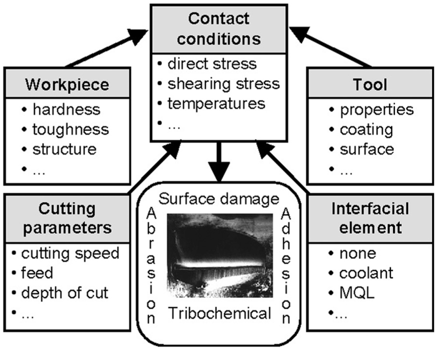
Cutting process as a tribological system (excerpted from Weinert et al. 6 ).
MQL techniques have been widely adopted into the aerospace and automotive industries for the machining of grey cast iron, aluminium alloy and titanium. However, scant research work has been done on MQL applications in the die and mould manufacturing industry.
Surface roughness
The most commonly used surface roughness parameter in the metal cutting industry is Ra, the arithmetic mean of the absolute values of the evaluation profile deviations from the mean line. In machining of the sculptured surfaces with a ball-nose milling cutter, the theoretical average surface roughness is traditionally predicted by the spherical-tool approximation model 16 which is expressed as
where D is the cutter diameter, fz is the feed-rate per tooth and ae is the step-over.
From equation (1), the theoretical surface roughness can be minimised by decreasing the feed-rate and/or the step-over, or by increasing the cutter diameter. In finishing operations of die and mould components with the sculptured surfaces, quite often the maximum cutter diameter used is limited by the part geometry. Therefore, in this application, the theoretical surface roughness is affected only by feed-rate and step-over. The results of a number of experimental studies on high-speed milling of hardened steel17–21 have shown that both feed-rate and step-over are influential machining parameters on surface roughness.
Objective
The purpose of this study is to investigate the potential benefit of integrating the widely established HSM process with MQL techniques in modern die and mould manufacturing. The effects of MQL on surface roughness, tool wear and dimensional accuracy in five-axis HSM finishing operation of an injection mould component were investigated. The results will benefit the industry by reducing machining time in finishing operation, polishing cost and related costs spent on coolant.
Experimental set-up and results
This research study was industry-orientated; the experiments were carried out in the production workshop of a selected die and mould manufacturing company with its standard machining equipment. The experiments designed for this study were based on the four approaches in HSM4,11 and the four tribological elements in MQL. 6 The test piece was designed specifically for this study (Figure 2); it resembled a core insert of an injection mould, with several sculptured free-form surfaces and an inclined planar surface where surface roughness and dimensional accuracy measurements were recorded. All cutting tests were performed on a Spinner U5-620 5-axis HSM centre, equipped with dry, flood and MQL facilities. The machining centre has a built-in pneumatic unit supplying lubricated compressed air for dry machining. The air is mixed with low viscosity (10 cSt) hydraulic oil (Castrol Hyspin AWS 10) at 600 kPa by Venturi effect through the top of the in-line oil reservoir. In the conventional flood set-up, 6% concentration oil emulsion cutting fluid (Houghton HOCUT 795B) was used. In the MQL set-up, Accu-Lube dual-nozzle external MQL supply system was used. Based on the study by Yan et al., 14 the MQL nozzles were set at the proven most effective position of 60° elevated angle and 120° with reference to feed direction (Figure 3). Based on the study by Tai et al., 12 the MQL lubricant used was a bio-degradable vegetable-based oil with added extreme-pressure (EP) additives by Accu-Lube (Accu-Lube LB-1000). It was specifically designed for heavy-duty machining application. It has a specific gravity of 0.93 and viscosity of 39 cSt at 40 °C. Based on the recommendations by the manufacturer, the MQL lubricant flow rate was set at 4.5 mL/h/nozzle under delivery air pressure of 600 kPa.
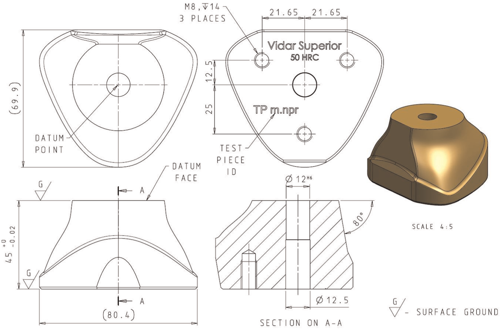
Detail drawing of the test piece.
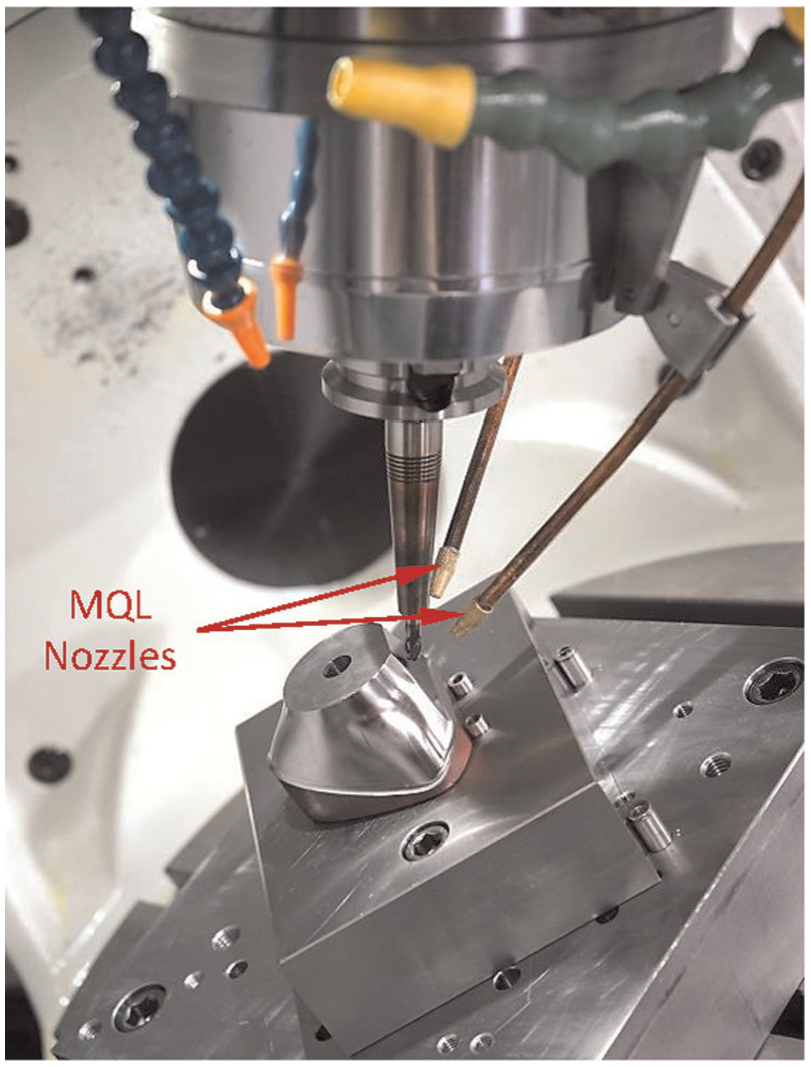
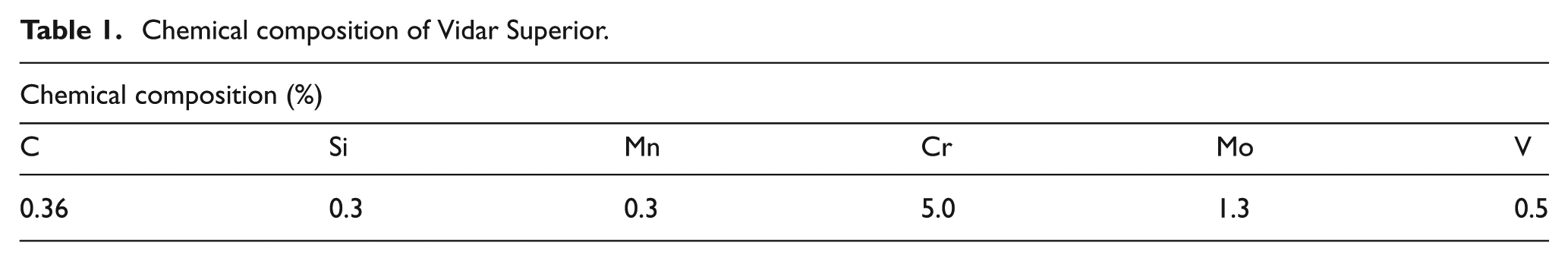
Mounted test piece with MQL nozzles.
The material chosen was ‘Vidar Superior’ (modified AISI H11), a newer grade of chromium–molybdenum–vanadium alloyed hot work tool steels produced by Uddeholm, Sweden. Table 1 shows the chemical composition of the material.
Chemical composition of Vidar Superior.
Since the main focus of this study is on the HSM finishing process, all test pieces were prepared for the main cutting tests (finishing) through roughing, heat treatment (hardened to 50 HRC) and semi-finishing processes, as commonly used in the die and mould manufacturing industry. As the physical size of the test piece was relatively small, 0.4 mm of material stock was left on each test piece from the semi-finishing process, to ensure that the cutting tools could cover sufficient surface area in the main cutting tests (finishing) for any noticeable tool wear to happen. This allowed four complete passes of tool paths to create the final shape. ISCAR 6-mm four-flute TiAlN physical vapour deposition (PVD)–coated solid carbide ball-nose end mills (EB060A08-4C6 IC900) were selected for this study and were held in shrink-fit tool holders to ensure minimum run-out and maximum rigidity. The total run-out was measured to be 0.006 mm. The type of machining strategy used was ‘5-axis Variable Zig Streamline’ with Relative Vector of −30° from Siemens NX8 computer-aided manufacturing (CAM) software. Based on a previous study by Toh, 22 climb (down) milling with upward feed and horizontal step-over tool path orientations were chosen for the experiments.
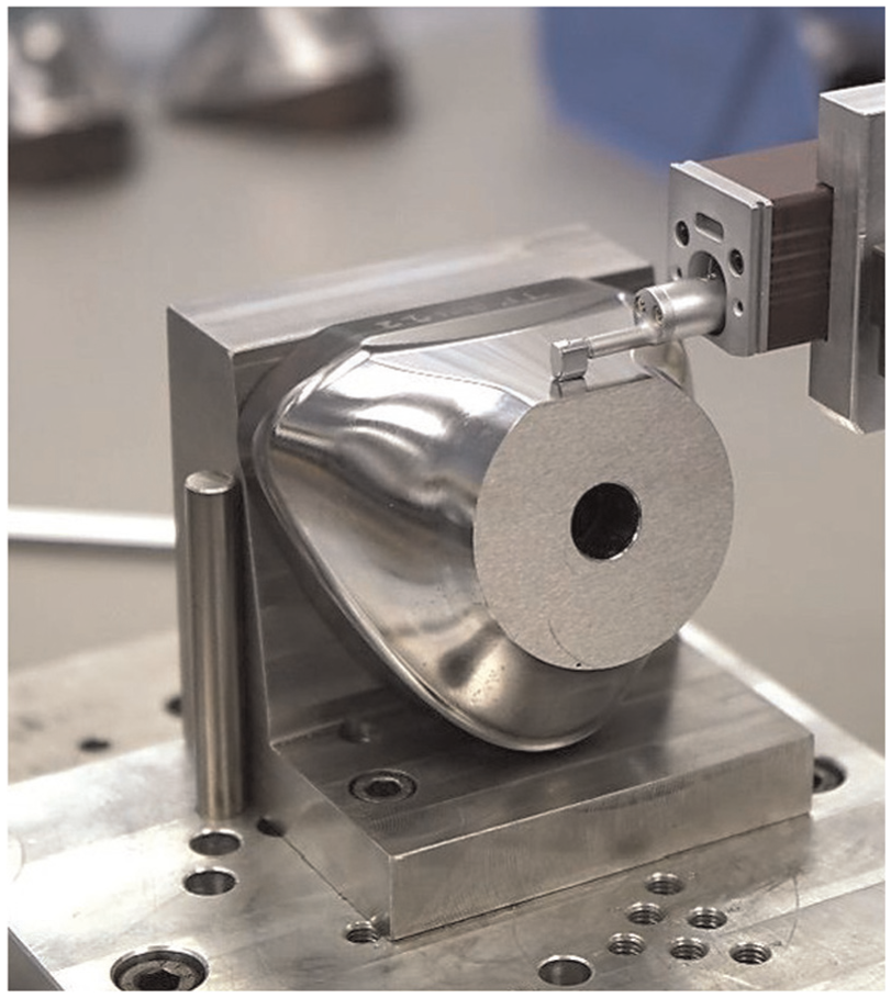
A Mitutoyo SURFTEST SJ-210 surface roughness tester was used to evaluate the surface finish of the inclined planar surface of the test pieces (Figure 4). The instrument was set to evaluate Ra, the arithmetic mean roughness, according to ISO4287:1997 roughness standard, with range of measurement between 0.1 and 2.0 µm. The tool paths created by the CAM software for this area were not rectilinear; therefore, the surface roughness along the feed and the step-over directions were both examined. Six positions on the surface arranged in a uniform pattern were chosen for examination (Figure 5). Three measurements were taken at each positions, and the average of the total 36 measurements was used for analysis.
Surface roughness measurement.
Surface roughness measurement design.
A Blum TC50 touch probe installed in the U5-620 machining centre was used to measure the dimensional accuracy of the test pieces (Figure 6). The dimension of three predetermined positions on the inclined planar surface was measured. The measured values were compared against the theoretical design values, and their differences (δy) were used for analysis.
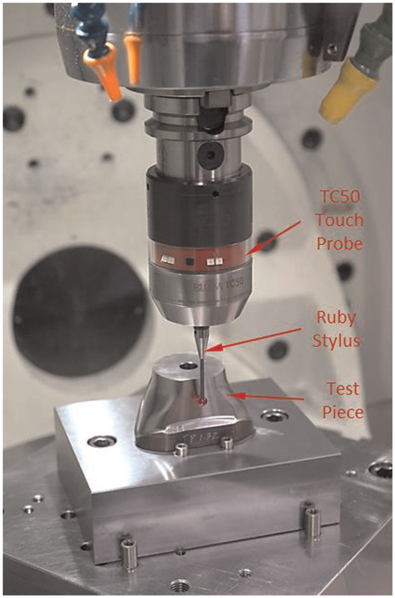
Dimensional accuracy measurement.
A Leica MZ16 optical microscope, connected to a personal computer, was used to observe the flank wear of the cutting tools. Images of the cutting edge, under 100× magnifications, were recorded by Irfan View 3.98 image capture software for flank wear measurement. The image of the Olympus 0.01 mm reference specimen was also recorded for measurement calibration. The flank wear was measured by means of the Fiji image processing software. Figure 7 shows a brand new unworn cutting edge.
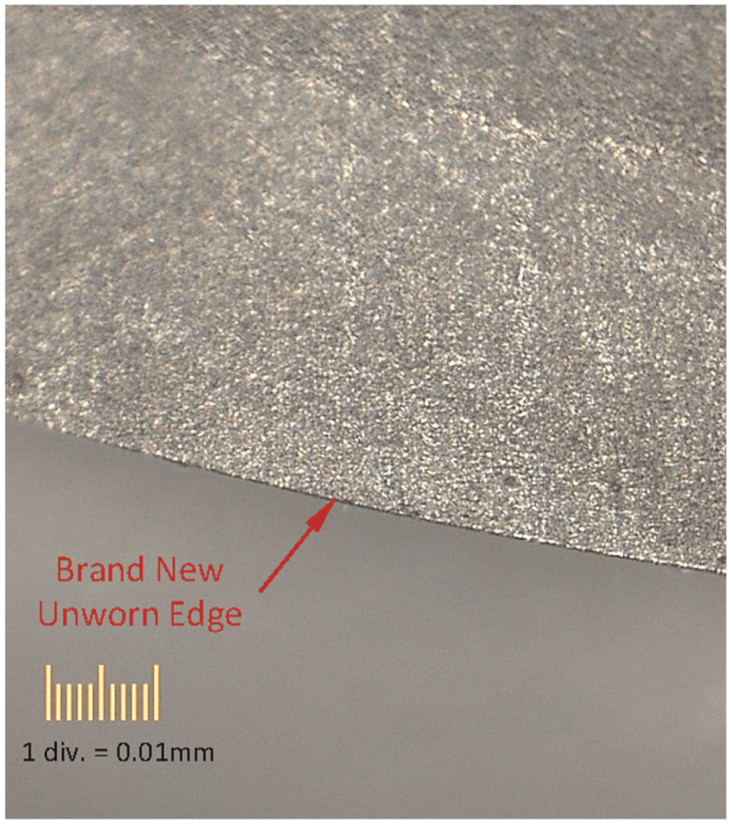
Unworn cutting edge.
Phase I experiments
Test pieces were machined under the three different cutting environments, dry, flood and MQL, under a constant cutting speed of 220 m/min. All cutting tests were conducted using the same machining parameter set ‘1’, namely, feed-rate (fz) of 0.03 mm/tooth, step-over (ae) of 0.1 mm and depth of cut (ap) of 0.1 mm. All the experiments were replicated twice and the test sequence was randomised; hence a total of six cutting tests were conducted. A machining time of 7.3 h for each test was recorded. The measurements of the surface roughness and dimensional accuracy of the inclined planar surfaces and the tool wear on each milling cutter are listed in Table 2. From the results, the achieved surface finish and tool wear under the three different cutting environments were very similar.
Result data of Phase I experiments.
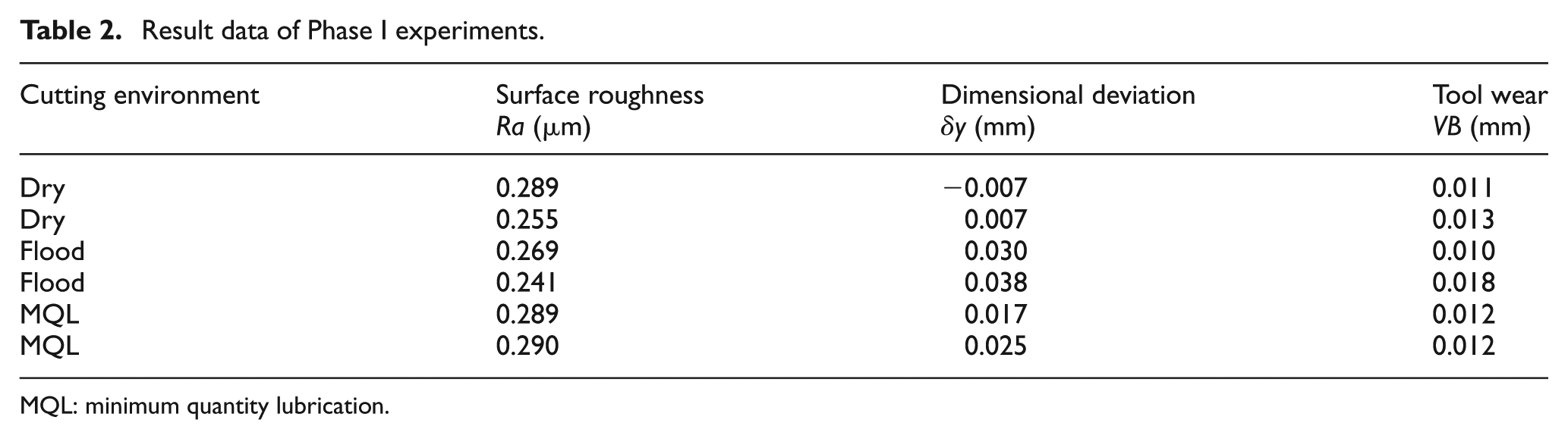
MQL: minimum quantity lubrication.
To establish the significance of these differences, one-way analysis of variance (ANOVA) tests were performed, with the significance level set at 5% (α = 0.05). From the analysis (Table 3), F values (2.119 and 0.288) were less than Fcrit (9.552) and p-values (0.267 and 0.769) were greater than ‘α’ (0.05), indicating that the variations in surface roughness and tool wear among these three lubrication methods were not significant.
Phase I ANOVA results.
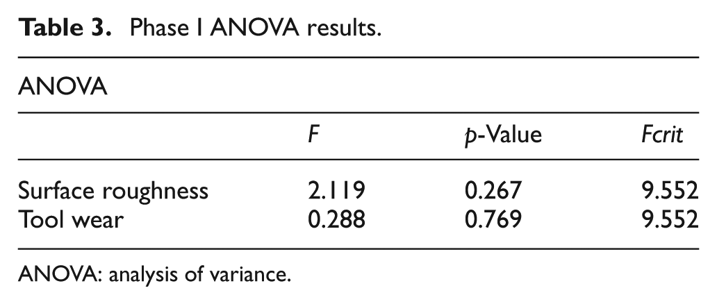
ANOVA: analysis of variance.
Phase II experiments
Analysis of Phase I results showed no significant differences in surface roughness and tool wear between dry, flood and MQL machining, suggesting there were no advantages in using the more expensive and environmental-unfriendly flood lubrication method over dry or MQL machining in the HSM finishing operation. Further experiments were thus conducted to investigate the potential benefits of using dry and MQL machining in modern die and mould manufacturing practice. A three-factor two-level one-half (23-1) fractional factorial design of experiment (DOE)23,24 was chosen to investigate the effect of feed-rate (fz), step-over (ae) and depth of cut (ap) on surface roughness and machining time under dry and MQL machining. In this DOE, the interactions between the three factors were assumed negligible. Hence, the results of the experiment could be expressed in terms of a mathematical regression model, written as

where
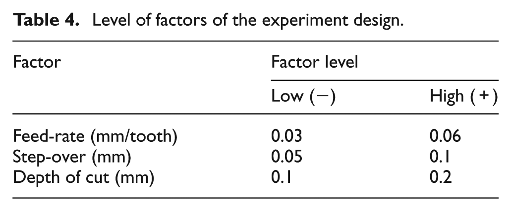
The level of factors and their combinations are shown in Tables 4 and 5, respectively. The high and low values of the three factors were selected based on common practice in the die and mould manufacturing industry.
Level of factors of the experiment design.
Factor values corresponding to machining parameter set.
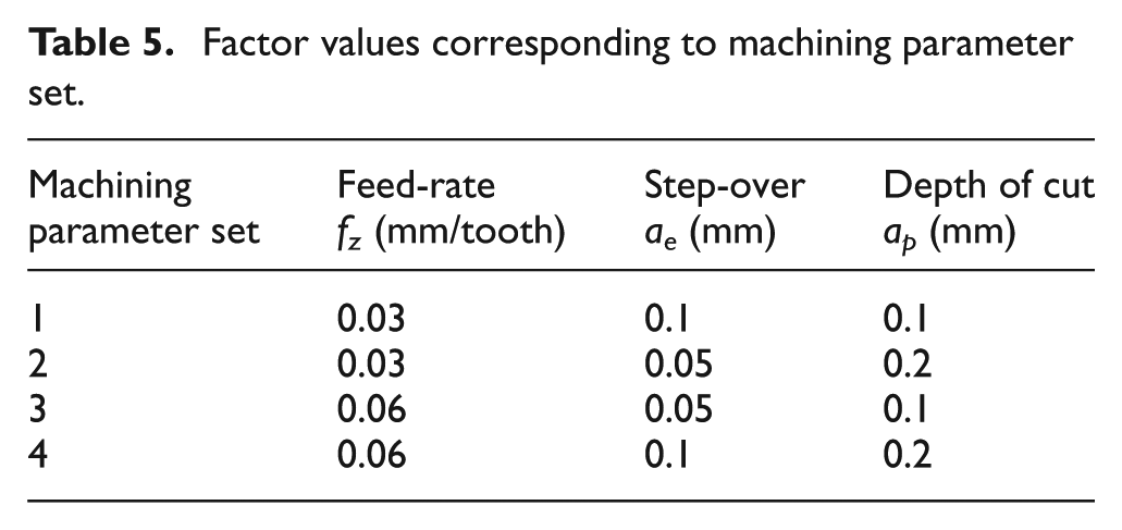
Similar to Phase I, all the cutting tests in Phase II were replicated twice and the test sequence was randomised to minimise experimental errors. According to this DOE, there should be 16 cutting tests in total, that is, 8 each for dry and MQL. However, since the cutting tests using machining parameter set 1 of the design were already performed in Phase I, they were excluded in this phase. Hence, only 12 cutting tests were conducted using machining parameter set ‘2’, ‘3’ and ‘4’. The complete results data, including those from Phase I, are listed in Table 6.
Complete results data of Phase II experiments.
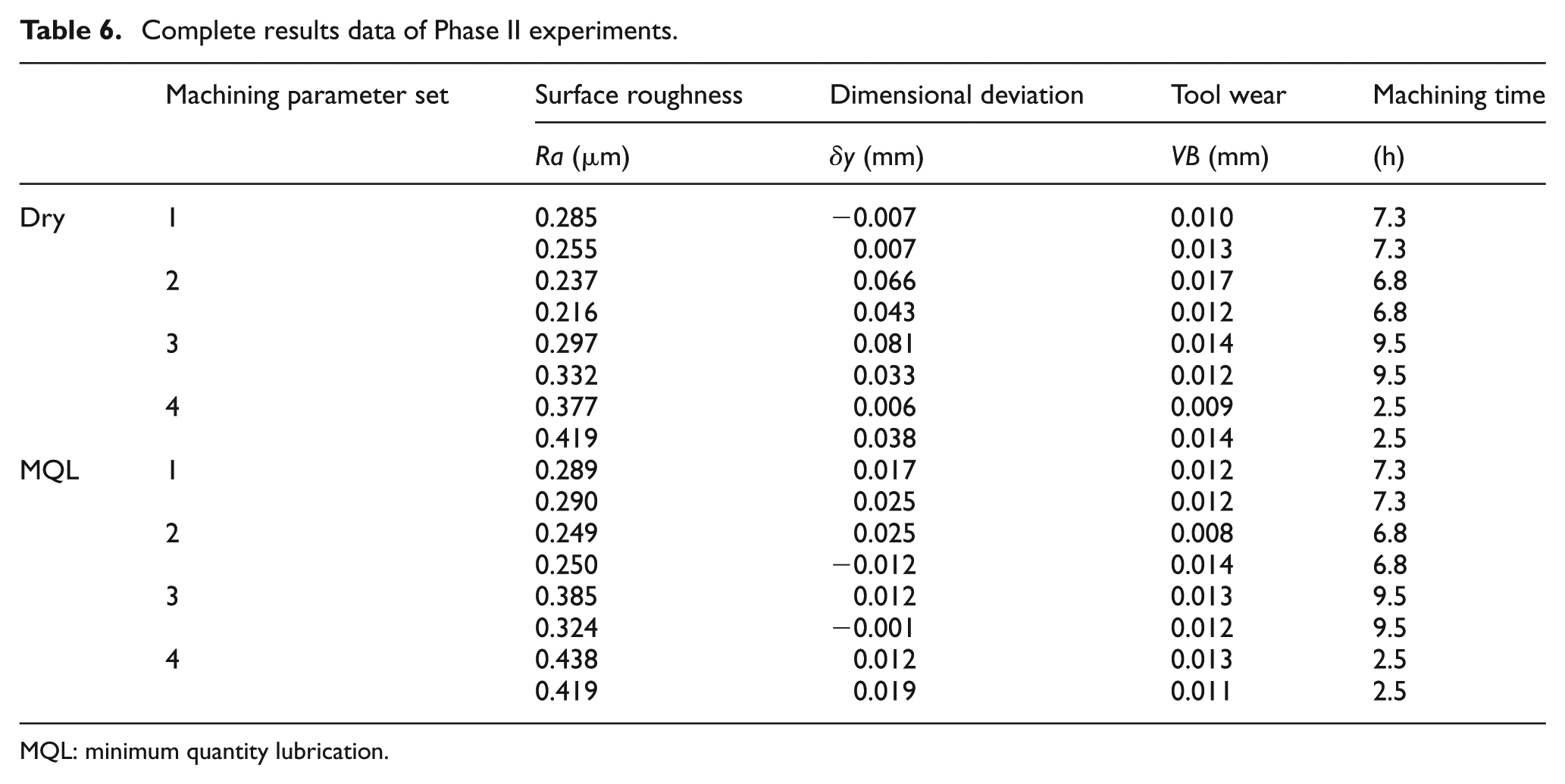
MQL: minimum quantity lubrication.
One-way ANOVA test was again performed with the significance level set at 5% (α = 0.05) to establish the significance of the differences in surface roughness, dimensional accuracy and tool wear between the dry and MQL cutting environments. Table 7 shows the ANOVA results for surface roughness, dimensional accuracy and tool wear, respectively. The results showed that in all the three cases, the values of F (0.616, 3.397 and 0.472) were less than Fcrit (4.6), and all the p-values (0.446, 0.087 and 0.503) were greater than α (0.05). This indicated that statistically there was no significant difference in surface roughness, dimensional accuracy and tool wear between dry and MQL machining.
Phase II ANOVA results.
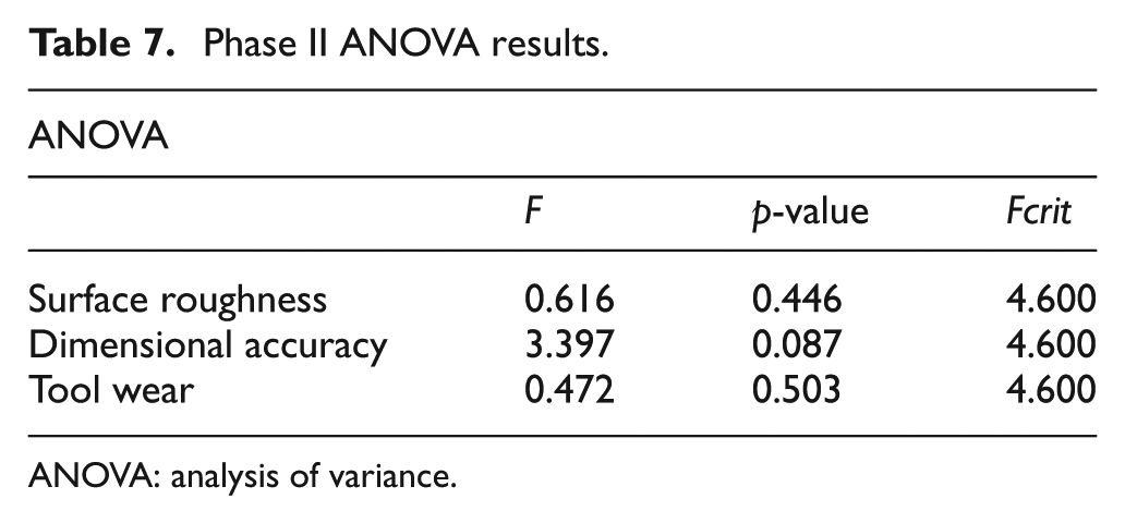
ANOVA: analysis of variance.
Discussions
Surface roughness
In Phase I experiments, the surface roughness values for all six test pieces were very similar (Table 2), ranging between 0.2 and 0.3 µm. The lowest was 0.241 µm from flood and the highest was 0.29 µm from MQL. From a die and mould manufacturing perspective, these were very good surface finishes. They were compatible to the results from grinding, honing and polishing processes. 25 Although flood machining produced slightly lower surface roughness than the other two cutting environments, the differences were very small (within the magnitude of 1/100th of micrometres) and statistically insignificant, suggesting that dry or MQL could be an alternative to flood lubrication method.
Phase II experiments showed a similar result pattern between dry and MQL machining (Table 6). Surface roughness values were again very similar under each of the different machining parameter combinations. Overall, dry machining produced slightly lower surface roughness than MQL (within the magnitude of 1/100th of micrometres), but the differences were statistically insignificance. A recent study by Yan et al. 14 suggested that improvement in surface finish could be achieved by utilising higher MQL oil flow rate. However, the results from this study showed otherwise; better surface finish was associated with lower oil flow rate, 0.4 mL/h in dry and 9 mL/h in MQL. A possible explanation of this phenomenon is that the viscosity of the oil lubricant has a more dominant effect on surface finish than its flow rate. A study of MQL lubricant properties by Tai et al. 12 indicated that low fluid viscosity was correlated with good machinability.
From the factorial experiment, regression models for surface roughness were established, for dry (equation (3)) and for MQL (equation (4))


Both equations can be used to predict surface roughness in relation to feed-rate and step-over. For example, if feed-rate = 0.03 mm/tooth and step-over = 0.1 mm, the resulting surface roughness will be 0.28 µm under near dry and 0.30 µm under MQL. Compared with 0.23 µm calculated by the spherical-tool approximation model (equation (1)), the prediction from the regression models was 22%–30% higher. This showed that the traditional approximation model can only be used as a rough estimation.
It can be seen from these two equations that feed-rate has a more dominant effect on the resulting surface finish than step-over, as it has a larger regression coefficient than that of step-over. This means that in order to achieve a better surface finish (low surface roughness), a lower feed-rate is preferable. When comparing the two equations, the ‘MQL’ model has a slightly larger feed-rate coefficient than that in the ‘dry’ model. This implies that when using the ‘MQL’ model for prediction, feed-rate has greater influence on surface roughness than in the ‘dry’ model.
Tool wear
The tool (flank) wear on all the 18 milling cutters was measured and was found to be very small, ranging from 0.009 to 0.018 mm (Tables 2 and 6). These differences proved to be insignificant irrespective of the differences in machining parameters and lubrication methods. They were all well below the tool-life criterion of 0.1 mm, which is typical for finishing operations in die and mould manufacturing practice. One of the contributing factors for the small flank wear was the high-performance coating of the milling cutters. The milling cutters used in this study were made of fine-grade solid carbide, PVD coated with submicron substrate of TiAlN. This high-performance coating is known to excel at machining difficult-to-machine materials such as hardened steels and nickel-based alloys; its superior oxidation resistance provides excellent performance in high-temperature machining. 23
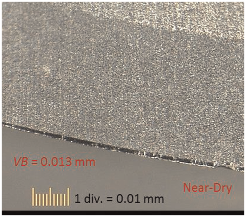
When comparing the wear pattern on the cutting edges after machining under the three different lubrication methods, worn edges resulting from dry and MQL machining were even (Figures 8 and 9). This was the result of abrasive wear. However, worn edges from flood machining (Figure 10) appeared to be uneven and wavy, which was the result of both abrasive and fatigue wear.26,27 During HSM of hardened steel, the heat generated by the cutting process created a temporary annealing effect on the workpiece surface which improves its machinability. This is similar to the effect of pre-heating the steel. 28 In the case of flood machining, the water-based cutting fluid cooled down the workpiece around the cutting zone, suppressing the annealing effect, and caused cyclic thermal loading on the cutting edge. This caused minute cracks perpendicular to the cutting edge to occur, allowing tool material particles to be released from the edge leading to the breakdown and failure of the edge. 27 This resulted in the wavy shape of the worn cutting edge. A possible explanation of the constant small flank wear phenomenon is that after the initial wearing or run-in of approximately 0.01 mm as shown in the results, further wear occurred at such a slow rate that even after more than 9 h of machining (using machining parameter set ‘3’), the additional amount of wear was insignificant.
Flank wear from dry machining.
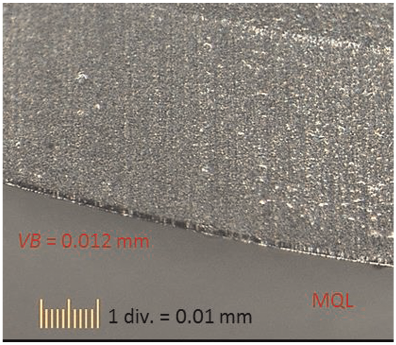
Flank wear from MQL machining.
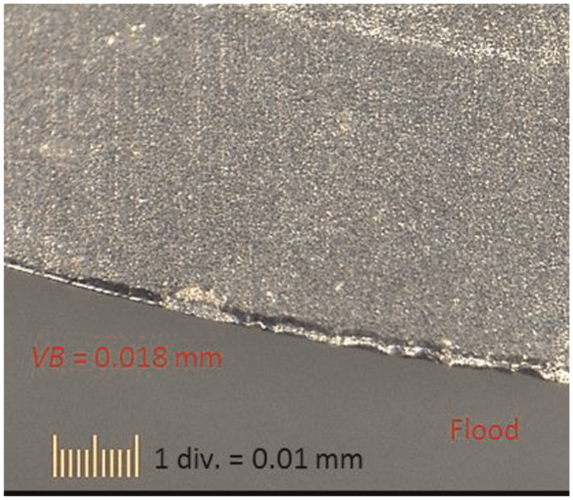
Flank wear from flood machining.
Dimensional accuracy
In HSM finishing operation of die and mould components, the accuracy of the machined workpiece is affected by the rigidity (e.g. tool overhang and vibration) and the accuracy (e.g. geometry and flank wear) of the cutting tool. 4 The milling cutter and holder used in this study were carefully chosen to eliminate possible errors caused by the above-mentioned factors. The maximum variation in cutting diameter was measured to be 0.005 mm and the total run-out of the milling cutter was 0.006 mm.
In Phase I experiments, the most accurate result, that is, average dimensional deviation of 0.007 mm, was obtained in dry machining, followed by 0.021 mm in MQL and then 0.034 mm in flood. Although the surface roughness was very similar in all three cooling/lubrication methods, flood produced the least accurate results. More experiments performed in Phase II on Dry and MQL machining showed that the average dimensional deviation was 0.035 and 0.015 mm, respectively. Although these differences were statistically insignificant, the dimensional deviation amount will determine the types of dies and moulds these two lubrication methods are capable of producing. For example, the accuracy produced by MQL machining fell within the tolerance requirement for injection moulds and forging dies, 29 while that produced by dry and flood machining fell within the tolerance requirement for die casting dies. 29
As discussed in the previous section, the tool wear was all similarly small in Phase I and II experiments. This suggested that tool wear was not the contributing factor to the cause and the variation in dimensional error of the machining. A possible cause for the dimensional errors could be cutter deflection. As the tool wear was very small in this study, most of the frictional energy created during the cutting process, which normally would have caused tool wear, 23 could be transformed into a reactional force perpendicular to the surface, thus causing cutter to deflect. A possible explanation for the dimensional variations could be that different frictional forces were generated by the cutting actions in the three lubrication methods, thereby causing the cutters to deflect in different amounts. As far as the properties of these three lubricants are concerned, the MQL lubricant (LB-1000) has a better lubricity property than the water-based cutting fluid used in flood. LB-1000 also contains an EP additive that withstands higher load. 12 Moreover, compared with the machine-built-in dry set-up, the MQL set-up provided a higher mist concentration as the nozzles were a lot closer to the cutting zone. Good lubricity, EP additives and high mist concentration have all been found to be best correlated with good cutting performance, 12 thus explaining the higher accuracy performance of MQL.
Machining time
From the results of the factorial experiment, a regression model for machining time was established (equation (5)), allowing the prediction of required machining time based on feed-rate, step-over and depth of cut

All three regression coefficients in this model are of a negative value, which means that using the upper level of the three parameters, for example, 0.06 mm/tooth, 0.1 mm and 0.2 mm, respectively, will result in the shortest machining time required, that is, 2.5 h. Using this model in conjunction with the surface roughness model (equation (3) or (4)), the shortest possible machining time required to produce the best surface finish can be predicted.
As previously discussed, surface roughness is not affected by the depth of cut while lower feed-rate (0.03 mm/tooth) will produce lower surface roughness. Hence, the best combination of machining parameters is fz = 0.03 mm/tooth, ae = 0.1 mm and ap = 0.2 mm. This will produce a surface roughness of 0.28 µm (using equation (3)) in 3.55 h of machining time. By reducing the step-over value, for example, to 0.05 mm, the surface roughness will be lowered by a small amount to 0.22 µm, but the machining time will be increased to 6.8 h. This means that it will take 3.25 h longer to achieve an insignificant gain in surface finish.
Conclusion
Experimental methodologies have been developed for investigating the potential benefits of applying the MQL technique in the die and mould manufacturing industry. Cutting performance in terms of surface roughness, tool wear, dimensional accuracy and machining time was examined. Initial experiments carried out on dry, flood and MQL machining revealed that dry and MQL performed equally to flood in surface roughness and better than flood in dimensional accuracy. This suggests that the dry or MQL techniques can be an alternative to and possibly a replacement for flood cutting environment in HSM finishing operation for die and mould manufacturing.
Further in-depth experiments carried out on dry and MQL machining revealed that their performances were comparable. Although they produced workpieces of the same surface roughness, workpieces from MQL machining had a higher dimensional accuracy. Based on these results, MQL may be more suited for the manufacturing of injection moulds and forging dies, while dry will be preferred for the manufacturing of die cast dies. Mathematical models for predicting surface roughness and machining time were established, confirming that feed-rate had a larger effect on surface roughness than step-over, while the depth of cut had no significant effect. In theory, an optimal machining time of 3.55 h and good surface finish of 0.28 µm can be achieved using a small feed-rate (0.03 mm/tooth), a large step-over (0.1 mm) and a large depth of cut (0.2 mm).
In conclusion, when combining the MQL technique with the right cutting conditions in modern die and mould manufacturing, machining and polishing time can be saved, thus contributing to an overall saving in production cost. The use of dry and MQL techniques in different finish machining situations can be a good economical solution for the die and mould manufacturing industry. However, as there are still limitations in applying this technique, in particular to the finishing operation, the implementation in real-life application has still to be thoroughly planned on a job-by-job basis.
Footnotes
Acknowledgements
The authors are grateful to CAMEX Limited for providing the machinery and equipment, Special Steels & Metals Limited for the test piece materials and ISCAR Pacific Limited for some of the cutting tools required in this study. The authors would especially like to thank Mr Terry Poole for his help in programming the cutting tool paths and his assistance in operating the five-axis machining centre. Without his expertise, the experiments would not have proceeded so smoothly.
Declaration of conflicting interests
The author(s) declared no potential conflicts of interest with respect to the research, authorship and/or publication of this article.
Funding
The author(s) received no financial support for the research, authorship and/or publication of this article.