
Abstract
Recently, mesh surfaces have become the focus of considerable interest due to its simplicity for data exchange and geometric computation. However, for mesh surface machining, there are few tool path planning strategies but iso-planar method. In this article, a contour-parallel tool path method is presented for machining complicated mesh surfaces with holes or islands by introducing a so-called one-step inverse approach based on physical plastic deformation of metal materials. By rapidly simulating for the inverse forming process of sheet metal of auto-body panels, the machined surfaces are flattened into its initial flat blank on which the cutter contact points are calculated by iteratively offsetting the inner and outer contours of the blank. Then, using the mapping from the machined surfaces to the blank as a guide, the planar offset curves without self-intersection are inversely mapped onto the original mesh surfaces, forming the final contour-parallel tool paths. Benefiting the flattening method based on one-step inverse approach, the task of generating tool paths is reduced from a physical surface to a plane so that geometric computation of tool path generation is greatly simplified, especially for self-intersection elimination in offset curves. Moreover, a new data structure of offset curve is also introduced, which is used to effectively compute the self-intersections. The proposed method has been tested on several sample surfaces, and the experimental results show that the proposed method can deal with complicated mesh surfaces with holes or islands and is also more efficient compared with the traditional methods.
Keywords
Introduction
At present, triangular mesh surfaces have gained nearly universal acceptance and are supported by most of current computer-aided design (CAD)/computer-aided manufacturing (CAM) systems, 1 in which complex mesh surfaces can be created directly from design surface or solid model and are stored as stereo lithography (STL) format that has been a de facto standard.2,3 Compared with parametric surfaces, in STL file, only the position of every vertex and the normal of every facet are recorded, so that mesh model can be handily translated between different CAD systems, and its related geometric computation is simpler and more robust than that of parametric surfaces due to the linear representation for design model. Recently, mesh surfaces have become the focus of considerable interest and been used as representation model for tool path planning.4,5 In most studies,6–12 mesh surface machining was often to be as a means to generate gouge- and collision-free tool path for machining free-form surface, and only one topology of iso-planar type is used. Although iso-planar methods are simple and robust, excessive short paths resulted from irregular or curved boundary of the surface make them very defective. Recently, several different planning strategies have been developed. Kim and Yang 13 proposed a cutter location (CL) surface deformation–based approach that first deforms CL surface to a new surface and then inversely maps the curves generated by slicing the CL surface into iso-scallop height tool paths. Lee et al. 14 extended further the concepts of the conventional guide plane and the drive surface and utilized a series of plane driven by side steps to slice the CL surface to generate iso-scallop tool paths. Makhanov et al.15,16 adopted grid generation technique to the tool path optimization and generated spiral tool path embedded into zigzag tool path on complex surface. Based on conformal maps, Sun et al. 17 proposed a spiral cutting strategy that realized cutting of mesh surfaces without tool retractions. These latest methods have explored tool path generation further for meshes machining from various perspectives.
However, there is a limited number of studies that have been performed on contour-parallel machining of mesh surfaces. Contour-parallel tool paths are widely used for sculptured surfaces or free-form surface machining 18 as it reduces the nonproduction time and also maintains the consistent up-mill or down-mill material removal during the cutting process. 19 In contour-parallel tool paths, a crucial issue is to eliminate self-intersection interference arising out of contour offsetting. Since offset curves are often represented by the discrete points and their connecting piecewise linear line segments, this causes some line segments nearly meet but do not really intersect, and thus, eliminating self-intersections directly on the surfaces is not usually desirable. For free-form surface modeled by parametric equation, self-intersection could be removed in u–v parameter space. 20 This might be not feasible for mesh surfaces because of its dependency on processing on parametric domain. To deal with this issue, Li et al. 21 have done some valuable works. They flattened the machined surfaces onto a plane by angle-based flattening (ABF) technique used widely in texture mapping. 22 On the plane, the self-intersection is removed easily using 2D curve offsetting algorithm. Their method works well for simple mesh surfaces, but not suitable for the surfaces with holes or islands often encountered in practice because their flattening method is only applicable to simple surfaces without holes.
In view of convenience and efficiency of generating the contour-parallel tool paths on complicated mesh surfaces with holes, this article adopts Li’s tool path principle and extends its ability to process the mesh surfaces with holes. A new flattening method is introduced in tool path generation by a so-called one-step inverse approach (IA) simulating the metal sheet inverse forming process. Moreover, an approach based on mesh topology to calculating the self-intersection points is also given to improve 2D curve offsetting algorithms. The rest of this article is organized as follows: Basic theory of flattening algorithm based on one-step IA is introduced in section “Flattening method based on one-step IA,” and section “Tool path generation” discusses the technical details of the developed method. Experimental results are presented in section “Experimental results,” and section “Conclusion and future work” gives the concluding mark and future work.
Flattening method based on one-step IA
The so-called one-step inverse approach (IA) is described as follows: As shown in Figure 1, given the mesh model of the final workpiece, the material property, thickness of the initial blank and the boundary conditions (blank-holder force (BHF), draw-bead restraining force (DBRF), friction force and constraints), requirement is to predict positions of the nodal in the initial flat blank and the distributions of the thickness h, strain
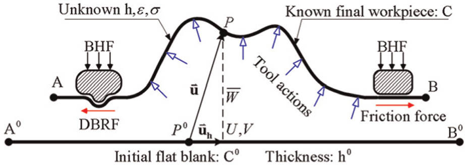
Illustration of one-step IA theory. 23
Before this, one-step IA is only used in sheet forming to predict the optimum blank shape and sizes and reasonable estimation of forming severity (i.e. strain distributions and thickness) from desired final workpiece. It is the first time to be used in numerical control (NC) machining. Previous work 23 of Li et al. has demonstrated that one-step IA can obtain the flattened meshes with lower area distortion and deal with irregular meshes with holes very well compared with other mesh parameterization method such as ABF++, and it can replace ABF to generate the tool paths on more complicated mesh surface. For integrity of our method, the basic theory one-step IA is reviewed as follows and the details of the mathematical description can be referred to our team’s works.23,24
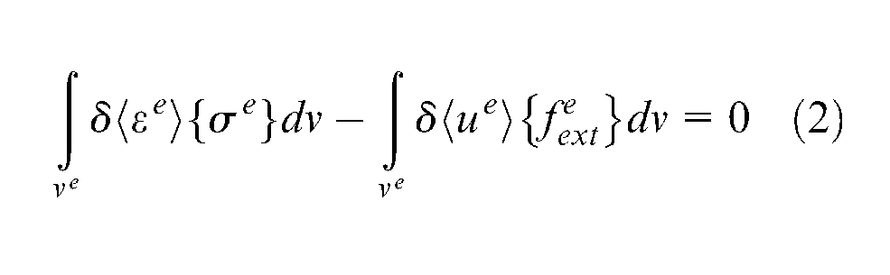
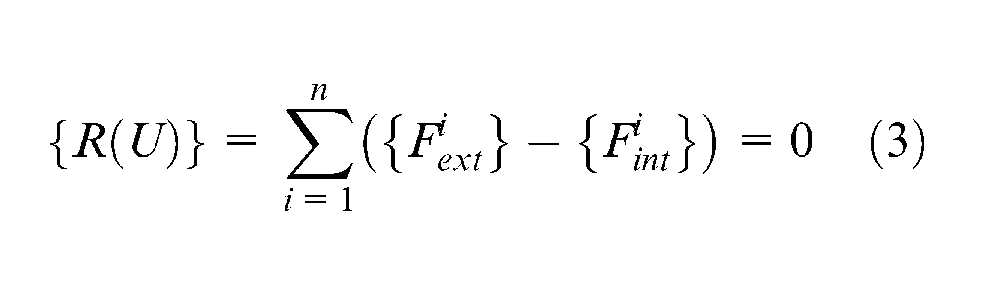
According to the principle of virtual work, the equation of energy of final workpiece is described as
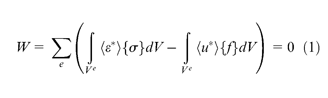
where
where
where
where

where
Tool path generation
Using the above flattening method, the machined surfaces are nicely flattened onto the plane. On this plane, the inner and outer boundaries of the blank are selected as the initial drive curves for curve offsetting. The developed tool path method adopts pair-wise offset (PWO) algorithm25–28 to generate the planar guide curves and improves further its performance using topology relations of mesh.
Self-intersection point calculation
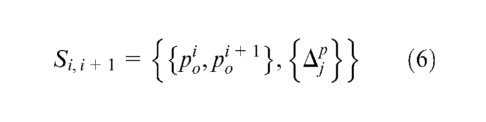
To calculate self-intersections efficiently, traditional offsetting methods often employ a grid structure over the initial offset curves to record the bounding bins that enclose each segment. Simultaneously, for each bin, the segments spanning over the bin are also recorded. Using a simple test for overlapping bin, a great number of attempted intersections can be avoided.19,26 For mesh surfaces, the above grid structure is unnecessary and can be replaced by the planar mesh surfaces itself. In the present method, when computing the initial offset curves using PWO algorithm, the offset point and its corresponding triangle, which contains the point, are stored as the following data structure

where
In this judging process, for each triangle
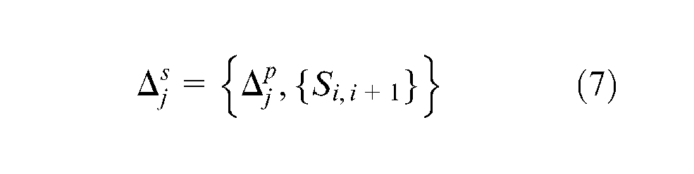
Using the above data structures (equations (6) and (7)), overlapping triangles
Offsetting strategy for boundaries
In the developed tool path approach, the offset distance or the path interval is determined according to the theorem in the study by Huang and Oliver 29 and changes with the surface curvature. As mentioned earlier, the inner and outer boundaries of the planar blank are selected as the initial drive curves and the offset curves are generated by PWO algorithm. Note that in the present method, for the convenience of processing, the inner boundaries are offset outward only once and other remaining machined region is implemented by inward offsetting the outer boundaries, as shown in Figure 2. The local and global self-intersection points in the initial offsets are calculated by the method of section “Self-intersection point calculation” and are removed automatically by PWO algorithm.
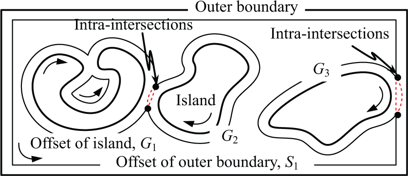
First offset of outer and inner boundaries.
The intra-intersections between the offsets of the outer and inner boundaries and the intra-intersections of the offsets of the inner boundaries themselves are also simultaneously detected using the method of section “Self-intersection point calculation.” If there are the intra-intersections among the offsets of the inner boundaries, the offsets will be merged into a united offset curve after eliminating the invalid loops. As shown in Figure 2, the offsets of left two islands,
Generating tool paths
Once the planar guide curves are generated, they can be inversely mapped onto the machined surfaces and generate the tool paths for machining mesh surfaces. According to the triangle
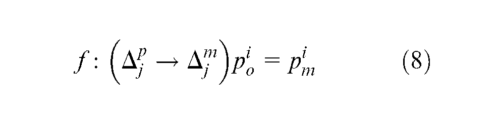
When mapping the guide curves, the step length has to be controlled such that the machining requirements can be satisfied. For mesh surfaces, in most CAD/CAM systems, the approximation error of the mesh surface to the original surface can be specified by the users such that a desirable triangulation to be adequate for NC machining is obtained conveniently, so only offset points and the intersections of the offsets and the edges are selected as cutter contact (CC) points. If the approximation error of mesh surface is equal to or less than an allowable chordal error of the step length, the step length of the generated tool path can be controlled reasonably. Then, the CC points
Experimental results
Implementation
All the algorithms mentioned above has been coded in C++ and implemented on a personal computer (Intel 3.0 GHz CPU, 4.0 GB physical memory). Geometric data of the surfaces are first retrieved from CAD model in Unigraphics 7.5 by selecting surfaces from the workpiece. The selected surfaces are triangulated into the mesh surfaces using the triangulation function provided by UG systems. Next, the mesh surfaces are flattened onto the plane using the method given in section “Flattening method based on one-step IA.” On this planar mesh surfaces, the proposed tool path method in section “Tool path generation” is used to generate contour-parallel tool paths for machining of mesh surfaces. The machining parameters used in experiment are given as follows:
Cutter: ball-end tool with diameter of Φ 10 mm;
Scallop height: 0.5 mm.
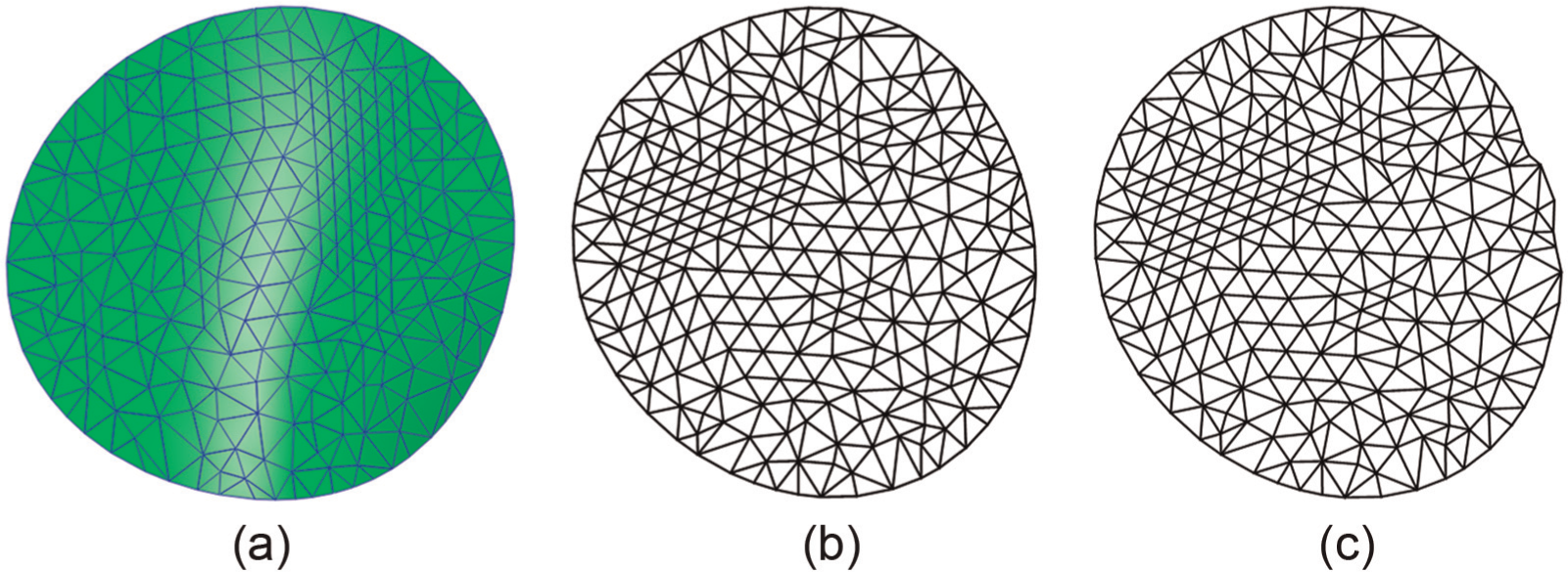
Comparison of one-step IA and ABF++
Two types of distortion, angular distortion and area distortion, usually used for evaluating the flattening algorithm in the literature, are measured. Angular distortion is defined as
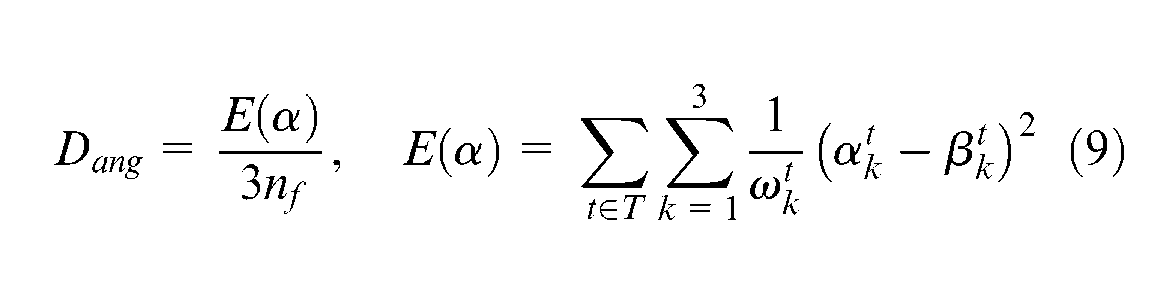
where
Comparison of one-step IA and ABF++.
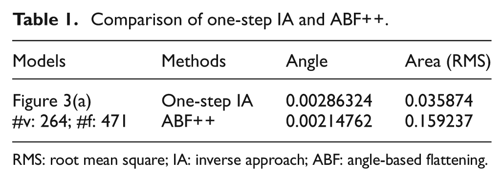
RMS: root mean square; IA: inverse approach; ABF: angle-based flattening.
Performance of improved pair-wise offset algorithm
In proposed method, traditional pair-wise offset (TPWO) algorithms are used to generate the initial offset curves. The self-intersections are computed by the method of section “Self-intersection point calculation” instead of using the traditional grid partition and are then eliminated by the orientation criterion. Since the procedure of the traditional grid or enclosing box partition is removed from the PWO algorithm, it is expected that the efficiency of the PWO algorithm will be further improved. Table 2 compares the execution times of the TPWO algorithm with improved pair-wise offset (IPWO) algorithm on two mesh models, as shown in Figure 4. The number of vertex and triangle of the two mesh models and their sizes are given in Table 2, respectively. It can be seen that IPWO reduces 18.3% and 21.6% execution times compared with TPWO. About 20% execution time can be saved by IPWO instead of using TPWO.
Execution times (ms) for two models in Figure 4.
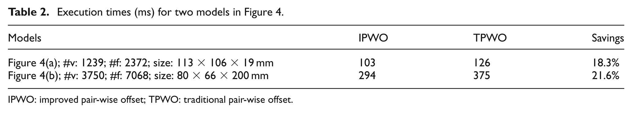
IPWO: improved pair-wise offset; TPWO: traditional pair-wise offset.
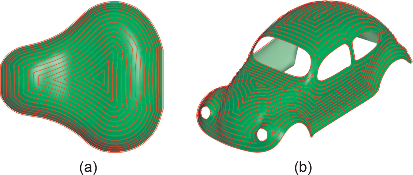
Two examples of offset curves on mesh surfaces: (a) bicycle seat, offset distance = 5 mm and (b) scale model of beetle, offset distance = 8 mm.
Tool paths for complicated mesh surfaces with holes
Figure 5(a) shows a joystick model, and the selected surfaces are typical trimmed surface with holes. To demonstrate the validity of the developed method, the selected surfaces are first converted into a triangular mesh surface which then is flattened onto the plane by one-step IA. On this plane, the boundary contours of the machined surfaces are iteratively offset using the method of section “Tool path generation,” forming the guide offset curves for generating tool path, as shown in Figure 5(b). The tool paths on the machined surface, as shown in Figure 5(c), are then obtained using the mapping
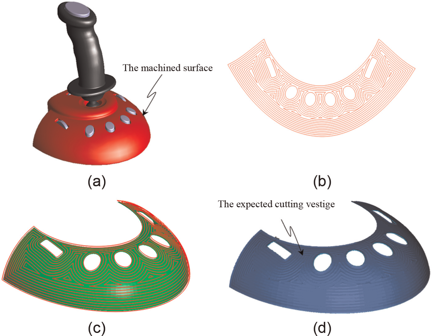
Contour-parallel tool path generation and machining simulation for the selected surface of joystick: (a) joystick model, (b) offset curves by improved PWO algorithm, (c) tool paths generated by our method and (d) machining simulation of tool paths.
Analysis and comparison with other methods
Benefiting from the mechanical background of one-step IA pointed out in the study by Li et al., 23 the proposed tool path method has no excessive restrictions on quality of the triangle meshes and can process more complex meshes in industry. These practical mesh models usually have invalid topology such as holes or ill-shaped triangles and are quite different from the scanning repositories used by the academic research in texture mapping of computer graphics (CGs). Therefore, compared to the tool path method based on the flattening algorithms of CG, 21 the developed method is relatively robust for the irregular mesh surfaces. Moreover, the new data structures of offset curve introduced by this article take full advantage of the topology relation of the mesh surface to compute the self-intersections in the initial offset curves, thus avoiding the procedure of the traditional grid partition, and experimental results show that this new data structure can effectively identify and compute the self-intersections and save about 20% execution times compared with those TPWO algorithms.25–27
Since the proposed tool path method is to map the offset curves on the planar meshes onto the machined surfaces to generate three-dimensional (3D) contour-parallel tool paths, it inherits the advantages of two-dimensional (2D) offset path of pocketing, and compared with iso-planar tool path of one-way and zigzag type,5,30 the generated tool paths have shorter nonproduction paths and consistent up-mill or down-mill stock material removal in cutting process and can conform nicely to the boundary of the surfaces, thus avoiding producing excessive short tool paths. However, the scallop height on whole surface is not constant compared with the iso-scallop tool paths 31 that meet the same cutting requirements such that the proposed method usually generates a longer tool path, but the maximum scallop on the surfaces does not exceed the limit of the user-specified scallop height.
Moreover, the basic theory of the proposed method can be used to eliminate the self-intersection arising out of iso-scallop tool path generation because iso-scallop path curve generation is also to offset geometrically the boundaries of the surfaces or curves on the surfaces by the path intervals on each CC points. 18 Similar to the process of contour-parallel tool path generation, the discrete representation of iso-scallop path curve causes that it is difficult to eliminate the self-intersections directly on the surfaces; thus, the raw iso-scallop path curves can first be mapped onto the planar surfaces on which the self-intersections are then removed by 2D offsetting algorithm. Undoubtedly, this can simplify the iso-scallop tool path generation.
Conclusion and future work
A contour-parallel tool path method is developed for mesh surface machining. The machined surface is mapped onto the planar domain, which reduces the task of eliminating complex self-intersection interfering from physical surface to 2D plane. Undoubtedly, this simplifies considerably the processing of self-intersection interference. The flattening method based on one-step IA is introduced, which is used in the proposed method to address those complicated mesh surfaces with holes in industry. Experimental results show that one-step IA can effectively flatten the mesh surfaces with holes and gives better shape of the flattened boundary. Moreover, new data structure of offset curve can avoid the grid partition procedure in the TPWO algorithms and save about 20% execution times, which has been confirmed by our experiments. It is noted that present method is only applicable to three-axis machining of mesh surface. For five-axis machining, the orientation of the cutter must be considered for generating gouge- and collision-free tool path, which is our work to do in the future research.
Footnotes
Declaration of conflicting interests
The authors declare that there is no conflict of interest.
Funding
This work was supported by the National Natural Science Foundation of China (grant nos 51105058 and 11102035).