
Abstract
With the rapid development of the modern manufacture, a radio frequency identification–based tracking network has been gradually established to monitor and track the material flows in a job-shop floor. Based on an event-driven graphical schema, this article puts forward a new method for modeling and analyzing the job-shop-type work-in-process material flows tracking network. The schema elements are mapped into the network nodes, and the association relationships among the elements are mapped into the network edges. Furthermore, corresponding measures and metrics are presented to evaluate the work-in-process material flows tracking network performance. Finally, a simple example is given to verify the feasibility of the proposed method. It is expected that this study will provide a systemic evaluation method for guiding and optimizing the radio frequency identification–based tracking configuration solution for job-shop-type material flows.
Keywords
Introduction
In order to realize flexible scheduling and visual management of a job-shop floor, it is important to collect and process the correct and real-time data from material flows. At present, the data acquisition methods, such as the manual recording, barcode and integrated circuit (IC) card, and so on, have been widely used in the production floor so as to track the work-in-process (WIP) material flows. Although the above methods have brought remarkable benefit for data collecting and automatic production, they also gradually reveal some shortcomings. 1 For example, the manual recording is time-consuming, inefficient, and error-prone; the barcode and IC card are particularly vulnerable to be contaminated in a bad running environment. With the rapid developments of wireless sensors, communication, and information network technologies, especially radio frequency identification (RFID), these advanced wireless techniques have provided new solutions for data collecting and computing of the modern manufacturing floor. Through attaching an RFID tag to a product or tray, the relevant material flows data can be automatically collected, processed, stored, and transferred to information decision center in a simple but efficient way. Compared with the traditional data collecting methods, the RFID-based technique has many advantages, for example, accurate and fast data gathering without human intervention, repeated use and large storage capacity of electrical tags, and prominent adaptability in a harsh environment. Besides, the RFID-based tracking allows to capture detailed material flows, such as transport between the machines, which are generally less often tracked in the traditional methods. The related industrial practices have also showed a great potential in supporting the automation of manufacturing process, improving production efficiency and achieving value-added service after applying RFID technique to the manufacturing floor. 2
In a job-shop floor, a process flow is considered as a sequence of actions/operations that happens on/around a series of machine tools, turning a workpiece from a material to a finished part, while a WIP material flow is considered as the flow of a workpiece in its specific process flow, from one position to another. It is well known that the goal of tracking the WIP material flows is to identify the state changes of workpieces together with collecting the changing time and position information of their states. 3 Through establishing the RFID-based detecting spaces around machines/equipment and attaching electrical tags to workpieces, the above information can be collected. Furthermore, owing to different data requirements from upper information systems, such as enterprise resource planning (ERP), manufacturing execution system (MES), and so on, the tracking decomposition particle size for the machining or inventory processes will be not unique. Relying on the decomposition particle size, the RFID-based configuration solution for tracking WIP material flows will be different, which may lead to different detecting effects. A reasonable configuration solution may raise the visual management level and improve the production efficiency; instead, an unreasonable configuration solution may bring the resource waste or incomplete tracking data, which will have a passive influence on the whole production scheduling. Therefore, it is urgently needed to analyze and evaluate the RFID-based configuration solution for tracking WIP material flows.
As an effective tool to analyze the system performance, complex network theory (CNT) has provided a new idea for investigating the tracking performance of the RFID-based configuration solution from the perspective of a topology network. First, this article focuses on describing and establishing a WIP material flow tracking network (WIP-MFTN) model, whose configuration solution is given and determined. Then, corresponding measures and metrics are presented to evaluate the detecting performance of the established WIP-MFTN. It is expected that a systemic evaluation method will be developed to guide and optimize the RFID-based tracking configuration of WIP material flows.
In order to achieve this goal, the rest of the article is organized as follows. Section “Related work” reviewed the related work of applying the RFID technology and CNT in the manufacturing industry. In section “Event-driven graphical schema for job-shop-type material flows,” an event-driven graphical schema is used to describe the job-shop-type material flows. Based on this description, the mapping rules between the graphical schema and the WIP-MFTN topology model are given in section “Mapping procedure between the graphical schema and WIP-MFTN.” Section “Performance measures and metrics of the WIP-MFTN” formulates the corresponding parameters for evaluating the WIP-MFTN performance. A simple example is provided in section “A case study: a job-shop-type WIP material flow including four processes,” followed by sections “Discussion” and “Concluding remarks.”
Related work
As an emerging technology, in the past few years, RFID-based automatic identification has gained a rapid development and its tag price has reduced much more. 4 Against this backdrop, it has been widely applied to product assembly, part fabrication, and transportation for realizing the real-time tracking, reducing management cost, improving process efficiency, and raising the service level.5,6 Much attention has been devoted to this topic not only in industrial practice but also in academic circles. Li et al. 7 highlighted the role of RFID in the emerging wireless internet manufacturing field. As an example, they investigated the case of Ford motor company that has successfully implemented RFID to improve the quality of products on the automated assembly production line. Liu et al. 8 designed a production management system (PMS) integrated with RFID-enabled real-time data capture system for Loncin motorcycle assembly line. Budak et al. 9 established a genetic manufacturing monitoring and analysis system through allowing a rapid development and deployment of an RFID-based manufacturing automation solution. Brusey and McFarlane 10 focused on the issue of correctly identifying, tracking, and dealing with objects in customized production with the use of RFID. Huang et al.11–13 and Qu et al. 14 presented approaches for deploying RFID-based wireless manufacturing technology for tracking and managing WIP inventories, walking-worker assembly islands, and adaptive assembly planning in job shops. Bindel et al. 15 discussed the application of an embedded RFID device into printed circuit boards for life cycle monitoring of electronic products to support product service systems. By comparing the timing of the RFID reads for the same tag, Mo et al. 16 developed a directional discrimination system in which the direction of the RFID tag movement can be discriminated. Furthermore, they established a two-dimensional positioning system using an RFID array, and the preliminary experimentation showed that this system was capable of locating an object with an average accuracy of 67 mm, using an array with a 350-mm spacing between tags. 17
In general, the presented research mainly focused on applying RFID technology to monitor and identify the state changes of products through the collection of manufacturing data. Furthermore, it can be used to help make the real-time decisions and realize the closed-loop control of production process, thus making job-shop process controlling more feasible and effective. However, previous research has paid little attention to evaluating the configuration and operation of RFID-based manufacturing system. It is much essential to present a systemic evaluation method for guiding and optimizing the RFID-based tracking configuration solution.
In a job-shop floor, a WIP material flow is considered as the flow of a workpiece in its specific process flow, from one position to another. In terms of the material flow equipped with the RFID devices, therefore, a variety of RFID-based tracking elements are formed in a complex system. While CNT18,19 is an effective tool for analyzing the structural characteristics of complex system, it has been increasingly applied to manufacturing field. On one hand, the applications are mainly focused on the manufacturing job shops. For example, Liu and Jiang 20 explored the inherent mechanism of machining error propagation through building a machining error propagation network. Zhang and Jiang 21 established a measuring and sensing network for analyzing product quality and equipment fault. Liu and Qi 22 applied CNT to mass customization and constructed a component relation network in which the modularization of a product family can be extracted. Through establishing a weighted network of complex product, Cheng and Chu 23 provided an assessment approach for change impacts. Vrabič et al. 24 presented a method of discovering autonomous structures in complex networks of work systems. On the other hand, much attention has been devoted to manufacturing networks. For example, Meepetchdee and Shah 25 proposed a logistical network design framework through introducing important performance measures, robustness, and complexity into the logistical network design objective. Xuan et al. 26 proposed a new framework to model and analyze the topological structure of supply networks, which suggested that real-world supply networks may benefit from its intrinsic mechanism on flexibility, efficiency, and robustness to target attacks. Zhang et al. 27 established an enterprise collaboration network supported by service-oriented manufacturing and adopted an improved genetic algorithm to find the optimal manufacturing blocks. The above literature suggests that the CNT has a great potential for analyzing the system performance, and it has provided a new idea for investigating the tracking performance of RFID-based configuration solution.
In this article, we first established an event-driven graphical schema to describe the job-shop-type material flows. According to the schema elements and their coupling relationships, a topology model for tracking the material flows was built. On that basis, the key performance parameters were proposed to evaluate the RFID-based configuration solution.
Event-driven graphical schema for job-shop-type material flows
In order to describe and formulate a material flow in job shops visually, an “event-driven” graphical schema model is proposed in the authors’ early articles.3,28 Table 1 shows the important concepts of the operations/actions, triggering times, positions, and workpiece states in this schema model. As illustrated in Figure 1, there are four steps to describe the WIP material flows using the event-driven graphical schema.
The important concepts in the event-driven graphical schema.
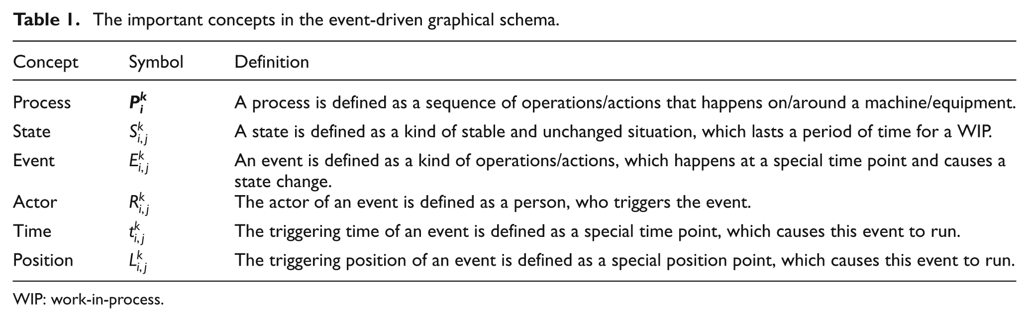
WIP: work-in-process.
An RFID-driven graphical method for describing the time-sensitive state and position changes of the WIP material flow in a job-shop floor.
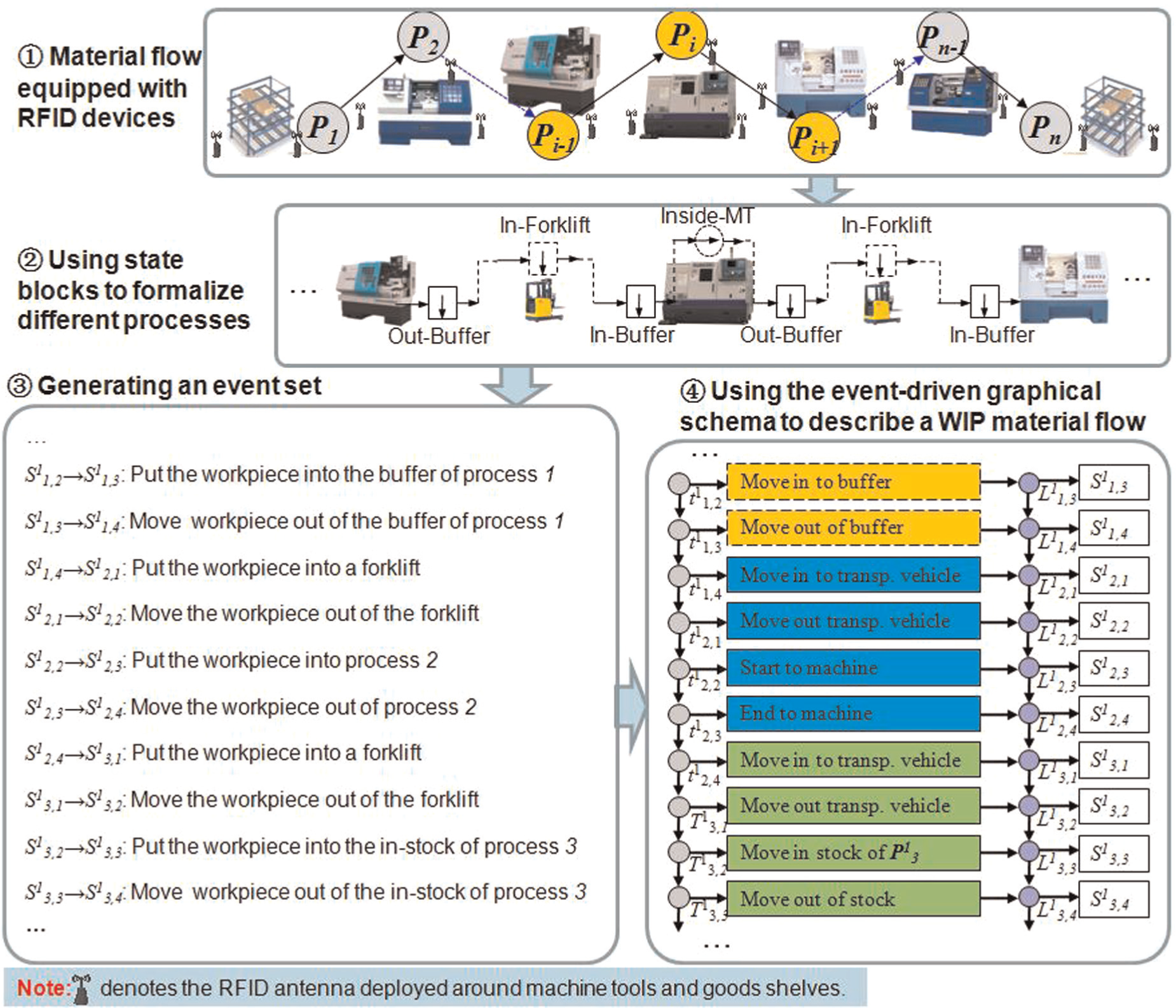
Step 1. Determining an RFID-based configuration solution based on process flow. In order to monitor the WIP material flow, RFID devices are deployed to/around the corresponding machine tools for collecting real-time data. According to the requirements from upper information systems, the decomposition particle size for a process
Step 2. Using state blocks to formalize different processes. The key point of tracking WIP material flow is to identify the state and position changes of a WIP. There are four types of RFID-driven detecting solution identifying whether the tags of kth WIP have entered, stored in, or left detecting spaces. The detecting spaces controlled by antennae include fixed space, mobile space, fixed gateway, and mobile gateway. Accordingly, there are four types of valid tag states “tag-moving-in,”“tag-storing-in-space,”“tag-moving-out/tag-moving-to,” and “tag-going-through.” The tracking configuration for a WIP material flow is the combination of four types of state blocks.
Step 3. Generating an event set automatically. Actually, an event is defined as one or more actions/operations that change the state continuously from one to another. The rule to generate an event set automatically is to build a process-related connection among state blocks that belong to different processes under the context of a WIP material flow. And then, an event can be modeled on the basis of a state pair si→si+1, which can be formulated as
Step 4. Using the event-driven graphical schema to describe a WIP material flow. As soon as formalizing all time-sensitive states, positions, and corresponding event sets in the WIP material flow of a workpiece, an extended event-driven graphical schema can be used to model such a material flow. This model can be formulated as
Mapping procedure between the graphical schema and WIP-MFTN
Through deploying RFID readers and antennas at different tracking nodes, the dynamic and real-time state information of WIP attached with electrical tags can be collected. Using the event-driven graphical schema, the time-sensitive states and position changes of WIP material flow can be formulated as
Furthermore, the above graphical schema model of describing the WIP material flows can be evolved from the perspective of a topology network. The tracking elements generated by schema model are mapped into the network nodes and the association relationships among tracking elements are mapped into the network edges. Therefore, a WIP-MFTN is developed. It can be described as G = (V, E), where V = (v1, v2, v3, …, vN) denotes a node set and
Mapping rules between graphical schema elements and WIP-MFTN nodes
In order to describe and formalize the WIP material flows, there are six element sets considered in the extended event-driven graphical schema. They are formulated as follows:
Machining or inventory process
Workpiece state
Event
Actor
Triggering time
Triggering position
Actually, one actor is usually responsible for one machining or inventory process in a job-shop floor, which means that the process
Mapping rules between graphical schema elements relationships and WIP-MFTN edges
There are two kinds of mapping relationships among the schema elements. One is the logic-sequenced mapping as shown in Figure 2 in which the detailed relationships among different schema elements are described.
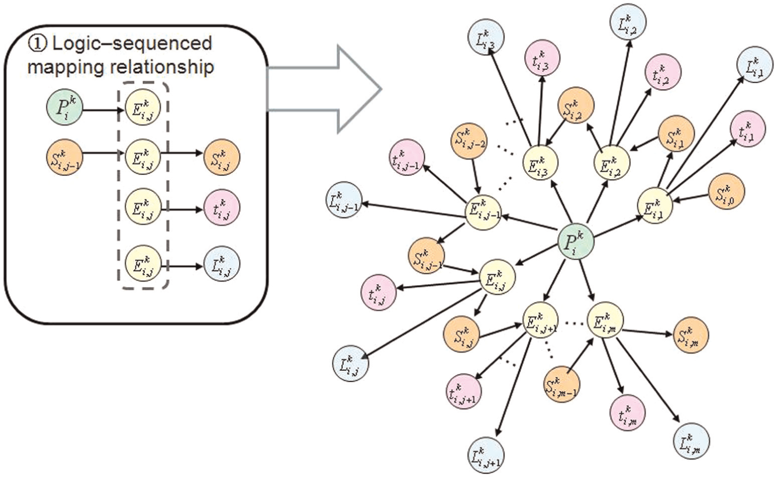
The logic-sequenced mapping relationship among schema elements.
The actor
The execution of the event
The execution of the event
The other one is time-sequenced mapping, as shown in Figure 3. In a job-shop floor, the machining or inventory process
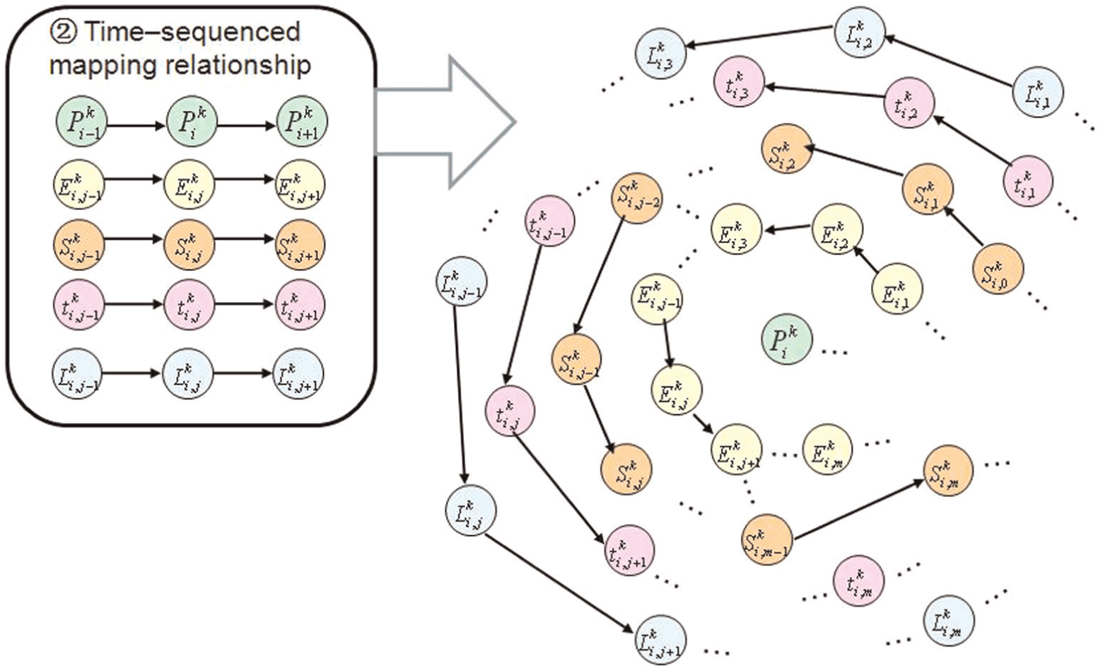
The time-sequenced mapping relationship among schema elements.
According to the mapping relationships of the schema elements, the mapping rules between graphical schema elements relationships and WIP-MFTN edges are described in Table 2. The total mapping relationships among schema elements for WIP material flows can be formulated as
Mapping rules between the graphical schema elements relationships and the WIP-MFTN edges.
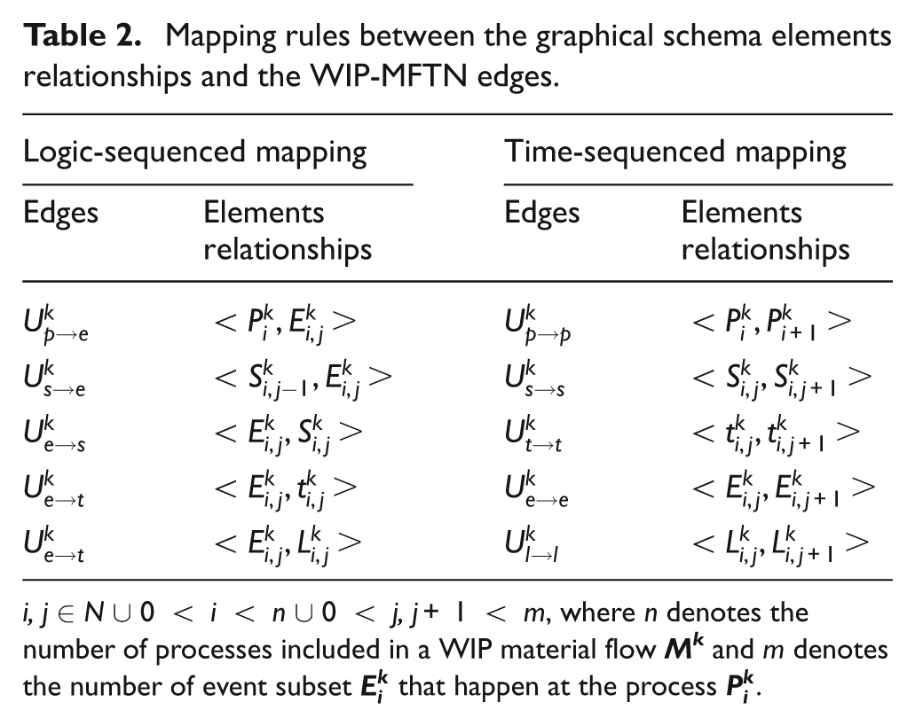
i, j∈N∪ 0 < i < n∪ 0 < j, j+ 1 < m, where n denotes the number of processes included in a WIP material flow
Topology modeling of the WIP-MFTN
According to the above mapping rules, a WIP-MFTN model can be established. Owing to the strict logic-sequenced and time-sequenced relationships among different nodes, the established WIP-MFTN
Figure 4 shows the topology model of the established WIP-MFTN.
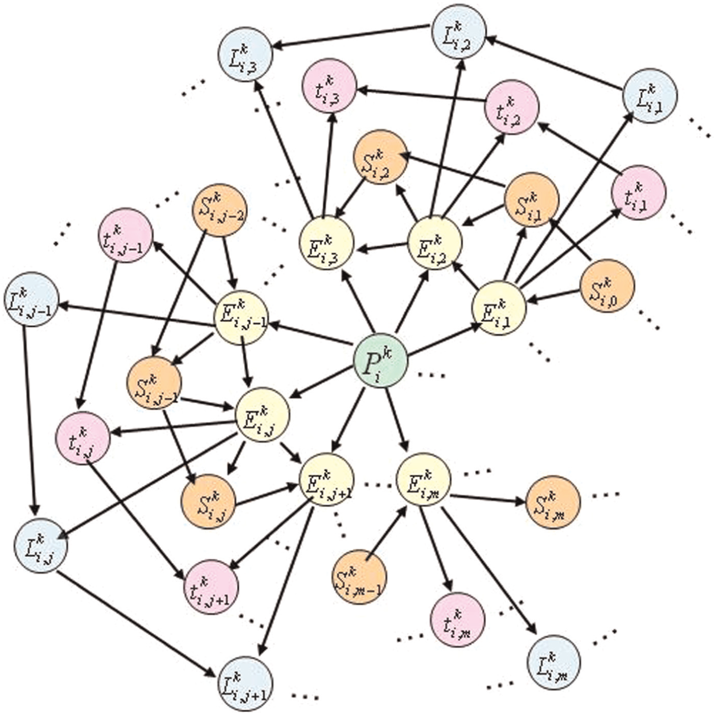
Topology model for the WIP-MFTN based on the event-driven graphical schema.
Encoding rule for the WIP-MFTN nodes
During the procedure of modeling the above WIP-MFTN, how to effectively manage and identify those schema elements is an important issue. In terms of the characteristics of different schema elements, a simple encoding rule is proposed here.
The kth workpiece for different batches production in a given time interval is denoted by WP_ID, and ID∈ [0, 99] consists of two numbers.
The machining or inventory process
The state
The events
The triggering time
The triggering position
Performance measures and metrics of the WIP-MFTN
This section mainly focuses on exploring the properties of the established WIP-MFTN by means of providing the corresponding definitions on performance measures and metrics. In the first subsection, much attention has been devoted to the investigation on the structural measurements, such as degree, clustering coefficient, shortest path, and so on. In the second subsection, much attention has been devoted to the investigation on the physical measurements, such as tracking particle size, configuration cost, vulnerability, and so on.
Structural measurements
Definition 1
The degree of node i in the WIP-MFTN is written as ki, which describes the local tracking importance of the node i. Because WIP-MFTN is a directed graph, the degree of node i has two components: the in-degree

where
Definition 2
The clustering coefficient of node i in the WIP-MFTN is written as ci, which describes the global tracking importance of the node i. Its value is obtained by calculating the ratio between ei and
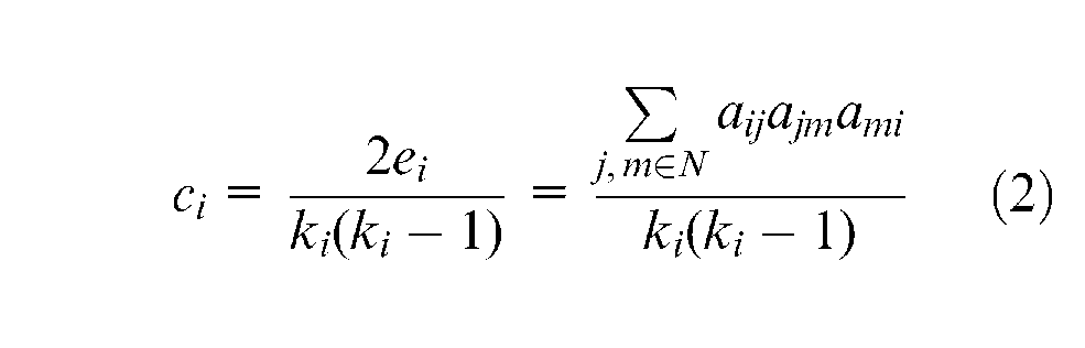
where ki denotes the number of the neighbors of node i;
Definition 3
The average clustering coefficient of the WIP-MFTN is written as C, which describes the global tracking importance for all nodes in the WIP-MFTN. The bigger the value of C, the closer the connections among different graphical schema nodes are

where N denotes the node number in the WIP-MFTN.
Definition 4
The shortest path of the WIP-MFTN is written as H, which describes the tracking efficiency of the WIP-MFTN. A higher efficiency can result in more frequent interactions among different graphical schema nodes. Therefore, it plays an important role in exploring the tracking characterizations of the WIP-MFTN
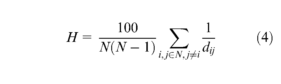
where dij denotes the shortest path between nodes i and j. It should be noted that dij can be
Definition 5
The state motif in the WIP-MFTN is written as ri, which describes a four-node (Ei, Si, ti, Li) directed subgraph within the network as shown in Figure 5. It must be pointed out that the state Si−1 is not included in this motif ri for it is treated as the input of this event Ei and the output of the previous event Ei−1. Actually, the motif ri is the basic unit of the WIP-MFTN, which reveals the subgraph generation principle of the WIP-MFTN owing to the happening of the event Ei.
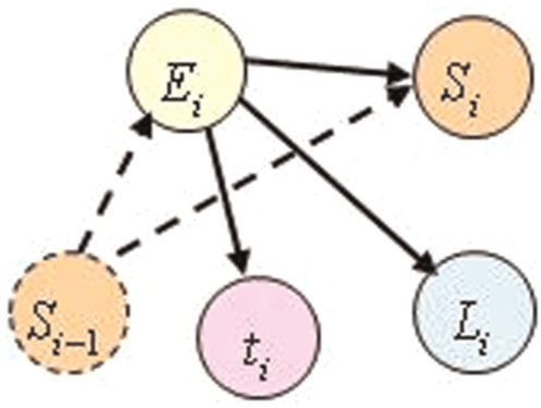
State motif consisting of four-node directed connected subgraphs.
The above definitions are mainly used to investigate the structural properties of the WIP-MFTN. On the basis of the above definitions, the metrics for analyzing the physical properties of the WIP-MFTN are provided below.
Physical measurements
Definition 6
The tracking particle size for machining or inventory process pi is written as αi. From the literature,3,28 we can get that the RFID-based detecting spaces are used to monitor the workpiece states. Therefore, the number of workpiece states during a process is corresponding with the number of RFID-based detecting spaces, and this parameter can be used to describe the tracking intensity of the process

where µij denotes the jth detecting space during the process pi. J denotes the number of the detecting spaces in the process pi.
Definition 7
The configuration cost for the RFID-based detecting space µij in the process pi is written as gij, which describes the expenses of fulfilling the tracking tasks. It must be pointed out that this cost comprises the expenses from purchasing, installing, testing, and maintaining the hardware and software of RFID readers/antennas

where ηl denotes the decomposed and smaller expenses during the normal service life for the RFID-based detecting space µij, such as installing.
Definition 8
The extending degree of the WIP-MFTN is written as νλ, which describes the network structural changes when adding λ motifs into the WIP material flow. It is defined as the ratio between new added degree and the previous one
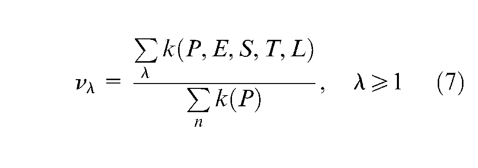
where
Definition 9
The physical vulnerability for the RFID-based detecting space µij is written as δij, which describes the error rate that the valid electronic tags going through or storing in the detecting space have not been well identified. In the area of industrial applications, the error rate of RFID devices has much to do with the environmental conditions. At present, most ubiquitous system engineers mainly rely on their experience, knowledge, and know-how in a trial-and-error manner when developing RFID systems. Here, this parameter is mainly obtained by the testing experiments in the site environment.
Definition 10
>The structural vulnerability for tracking workpiece state si in the WIP-MFTN is written as ui, which describes the failure behaviors of the WIP-MFTN when the workpiece state in the WIP-MFTN has not been well identified. Since the failure in identifying the workpiece state si can lead to that the state motif ri has not been executed, the structural vulnerability ui can be defined as the degradation rate of network efficiency for removing the ith state motif from the WIP-MFTN. The larger the value of ui is, the more important the state motif ri is

where H denotes the efficiency of the WIP-MFTN and Hi denotes the efficiency after removing the state motif ri from the WIP-MFTN.
Definition 11
The comprehensive vulnerability for tracking workpiece state si is defined as the Ui, which describes the spreading effect in the WIP-MFTN when the valid electronic tags have not been well detected. It is a comprehensive evaluation parameter integrating the physical vulnerability and structural vulnerability

A case study: a job-shop-type WIP material flow including four processes
The WIP-MFTN including four processes
This section provides a case to verify the feasibility of the proposed methods. Figure 6 illustrates a simple WIP material flow in a job-shop floor including four processes, which is a real scenario generated from “State Key Laboratory for Manufacturing Systems Engineering” of Xi’an Jiaotong University. In this case,
The RFID-based configuration solution for tracking the WIP material flow.
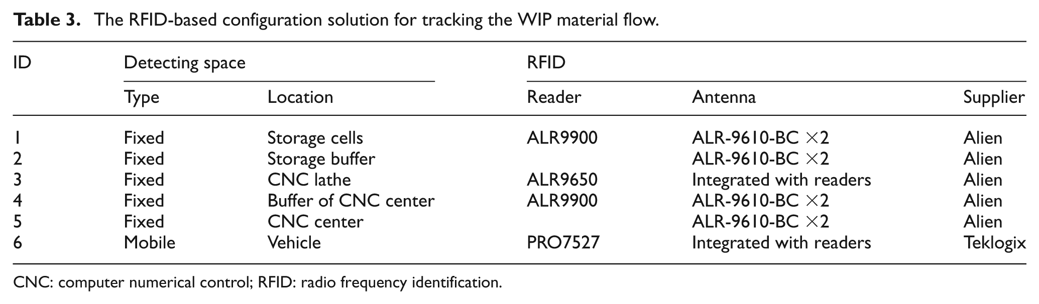
CNC: computer numerical control; RFID: radio frequency identification.
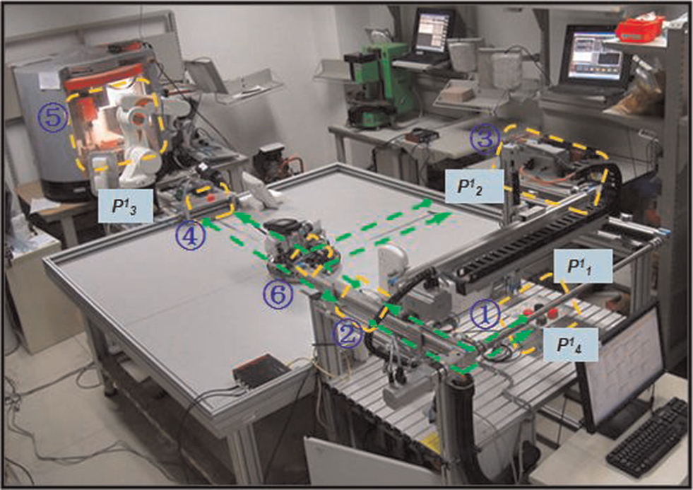
A real case for a WIP material flow including four processes.
According to the above RFID-based configuration solution, the time and position changes of the WIP states can be identified. Using the event-driven graphical schema, the WIP material flow can be formulated. Figure 7(1) shows the above WIP material flow including four processes, in which corresponding RFID devices are deployed; Figure 7(2) shows its graphical description in terms of using state blocks; Figure 7(3) presents four groups of event sets concerning those four processes; and Figure 7(4) deals with modeling the above four processes by means of using the extended event-driven graphical schema.
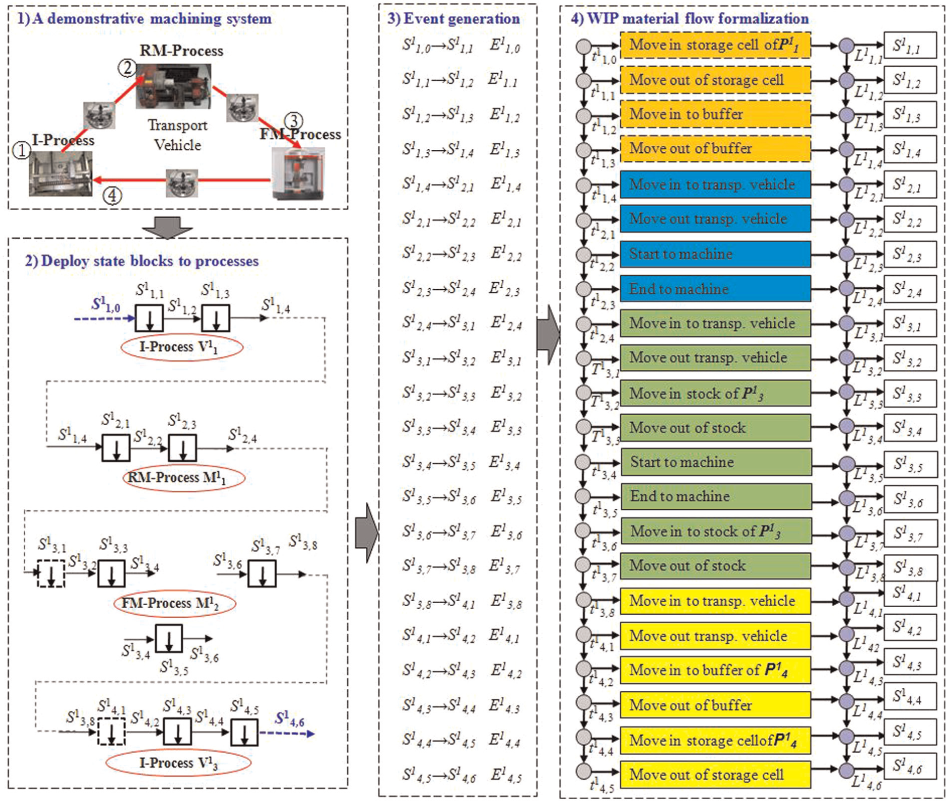
The WIP material flow described by an event-driven graphical schema.
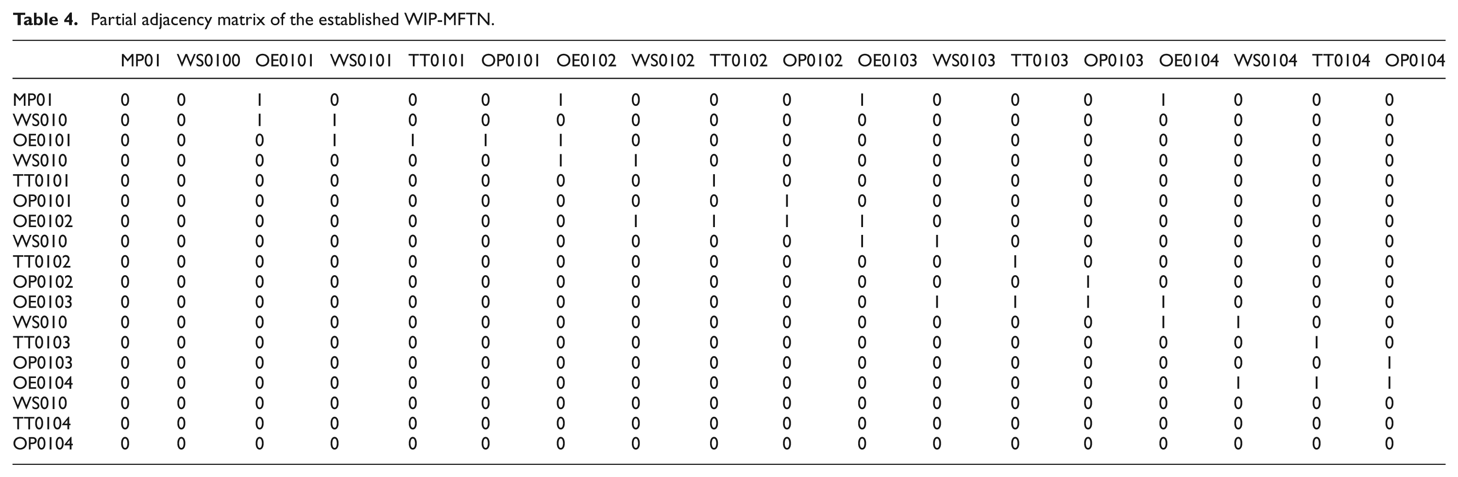
According to the above graphical schema for describing the material flow, 93 schema elements are extracted to establish a WIP-MFTN. Specifically, there are 4 process nodes (MP01/MP02/MP03/MP04), 22 event nodes, 22 triggering time nodes, 22 position nodes, and 23 state nodes. It is noted that initial state (WS0100) is involved in this topology network since it is used as the input state of the WIP. The partial adjacency matrix of the established WIP-MFTN is shown in Table 4. The adjacency values among nodes are determined by the mapping rules among schema elements. In addition, the adjacency values between the same nodes are set to zero.
Partial adjacency matrix of the established WIP-MFTN.
Based on the adjacency matrix A(G), the topology model of the WIP-MFTN is shown in Figure 8. The MP-XX nodes represent machining processes; the OE-XXXX nodes represent operation events; the WS-XXXX nodes represent the WIP states; the TT-XXXX nodes represent the triggering times; and the OP-XXXX nodes represent the operation positions. It is noted that the established WIP-MFTN is a regular and directed network.
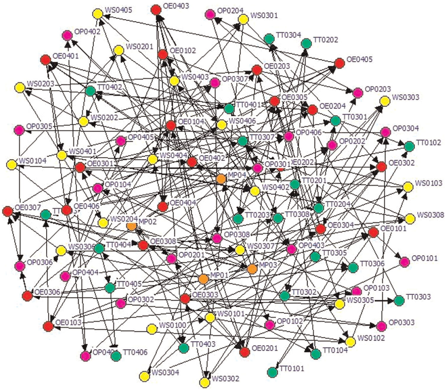
Topology model for the established WIP-MFTN.
The performance evaluation of the established WIP-MFTN
On the basis of the established WIP-MFTN, the corresponding performance evaluation metrics were calculated and their analysis results were outlined as follows.
The small-world property
As shown in Table 5, the average shortest path (H) for this WIP-MFTN is 2.416 and the clustering coefficient (C) for this WIP-MFTN is 0.098. But by contrast, for the random network with the same size (nodes = 93/edges = 198), the average shortest path is 5.998 and the clustering coefficient is 0.023. The calculated result shows that this established WIP-MFTN has both a small shortest path (like random graphs) and a high clustering coefficient (like regular graphs). Therefore, this WIP-MFTN has the small-world property.
The comparison between the WIP-MFTN and the random network with the same size.
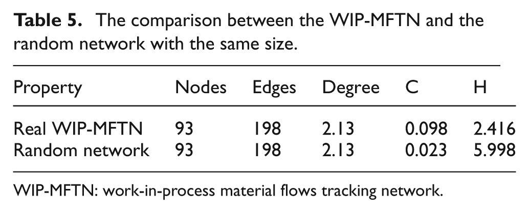
WIP-MFTN: work-in-process material flows tracking network.
This small-world property of the WIP-MFTN plays an important role in evaluating the tracking performance of material flows. On the one hand, the high clustering coefficient denotes the close connections among different graphical schema nodes. On the other hand, the small shortest path denotes the efficient connections among different graphical schema nodes. Therefore, the small-world property reveals the tracking efficiency of material flows. According to the above analysis, the established WIP-MFTN has an efficient tracking performance of material flows.
Scale-free degree distribution
The degree distribution of a scale-free network follows a power law for large k,
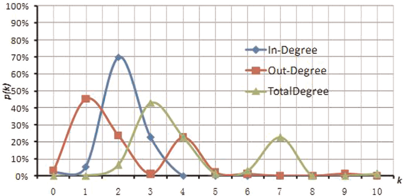
In/out/total degree distribution curves for the WIP-MFTN.
In general, the above structural properties have a lot to do with the mapping rules between the event-driven graphical schema and the WIP-MFTN. However, these analyzing results about structural properties will provide a basis for investigating its physical properties.
Configuration complexity
In this case, there are two machining processes and two inventory processes considered. Owing to their different roles in the whole job-shop-type production and user’s monitoring requirements, the tracking particle size for each process is different from others. At the inventory process of raw material and finished products, two detecting spaces are deployed around the storage cell and buffer, respectively. At the rough machining process, one detecting space is deployed around a computer numerical control (CNC) lathe. At the finished machining, two detecting spaces are deployed around the buffer and machining area of a CNC center. According to the above particle size for tracking WIP material flow, the RFID devices made by Alien and Teklogix are deployed to fulfill the configuration tasks. And their costs for purchasing, installing, testing, and keeping the corresponding readers/antennas are listed in Table 6. In terms of the list, the total RFID-based configuration cost for establishing this WIP-MFTN is $11,940.
The cost list for implementing RFID-based configuration solution.
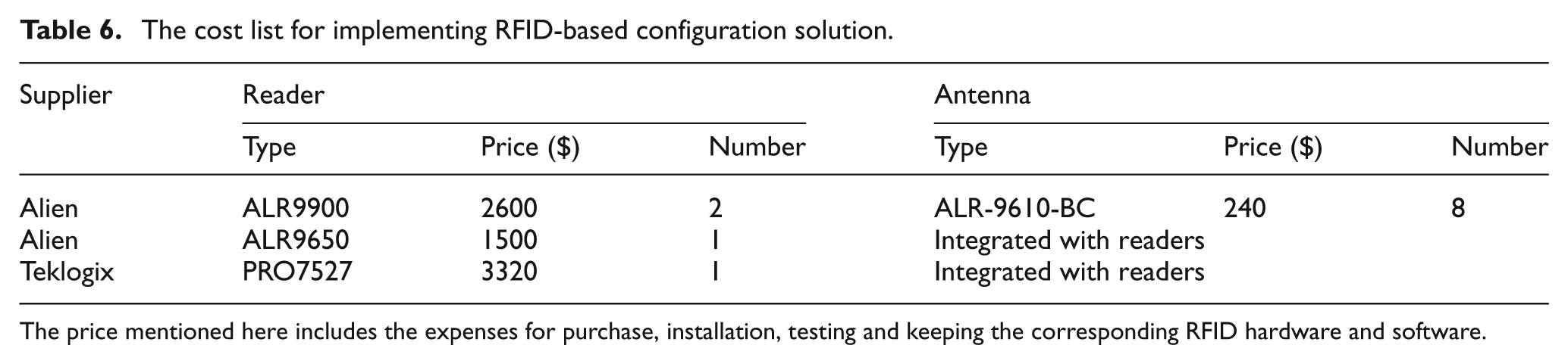
The price mentioned here includes the expenses for purchase, installation, testing and keeping the corresponding RFID hardware and software.
Therefore, the determination of tracking particle size for one process is largely influenced by the production and user’s monitoring requirements. Usually, the simplest configuration case is to detect the “move-in/move-out” states of workpieces during a process, while the most complicated configuration case is to detect all the states of the workpieces during a process. Obviously, the smaller particle size can lead to the more RFID-based configuration cost. In this case, the RFID-based configuration solution is the trade-off between tracking requirements and cost.
Network-extended property
In the practical production, it is essential to dynamically add or delete the detecting spaces in terms of the real-time monitoring requirements. Based on the calculating result of the structural metrics, this subsection pays more attention on the network-extended property of the WIP-MFTN for adding new detecting spaces. As is well known, the detecting spaces are used to monitor the workpiece states, and the state changes of workpieces happen by the actions/operations from operators. In order to facilitate our study, here, the motif is the basic unit for analyzing the extended property of the WIP-MFTN.
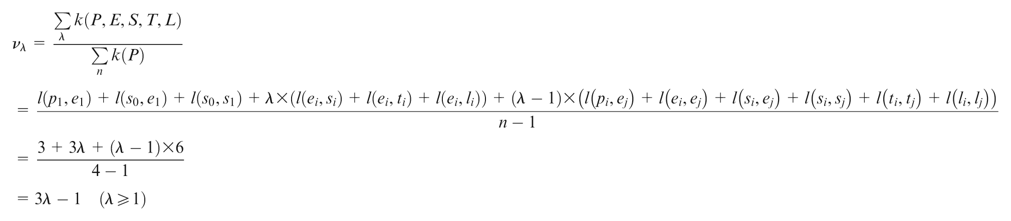
On the one hand, we have examined the extending degree for adding λ motifs into the WIP-MFTN. The detailed extending degree vλ for this WIP-MFTN is formulated as the ratio of the new network degree to the original network degree. It is noted that the initial WIP-MFTN includes five element nodes, which are MP01, MP02, MP03, MP04, and WS0100 and its original degree is 3
where l(xi, xj) denotes the coupling relationship between element xi and element xj. The calculating formula shows that the network structure of WIP-MFTN has significantly increased when adding λ motifs into the original network.
On the other hand, we examined the growth model, which is defined as the changes of the node number, total degree, average degree, and shortest path when adding a new motif into the WIP-MFTN continuously. As shown in Figure 10, it can be concluded that the node and degree of the WIP-MFTN are in an approximately liner increase with the adding of new motifs. Figure 11 reveals that the average degree of the WIP-MFTN tends to be stable with the addition of new motifs. On the contrary, the shortest path of the WIP-MFTN has a continual growth.
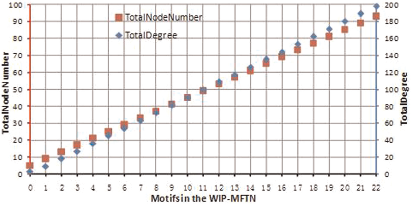
The node and degree changes of the WIP-MFTN with the new motifs added continuously.
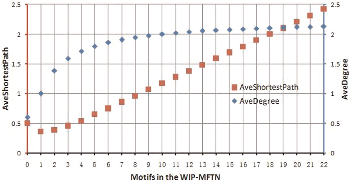
The average degree and shortest path changes of WIP-MFTN with the new motifs added continuously.
To sum up, the above analysis results reveal the generating principle of a WIP-MFTN and further confirm that the established WIP-MFTN is a regular network.
System vulnerability
According to the above analysis about the extending degree and growth model of the WIP-MFTN, we can conclude that the established WIP-MFTN has a unique network structure. This subsection mainly focuses on discussing the WIP-MFTN vulnerability. Here, the physical vulnerability is considered as the undetected probability when the workpieces attached with valid tags passing through or storing in the valid detecting spaces. Through adopting the statistical analysis technique, the error rates of RFID-based detecting spaces in this case are tested. The testing result is shown in Table 7.
The testing result for RFID readers and antennas detecting valid tags.
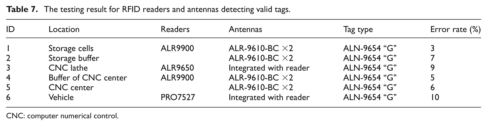
CNC: computer numerical control.
The structural vulnerability for tracking the WIP material flow is considered as the degradation rate of network efficiency for removing the motif from the WIP-MFTN. Its comprehensive vulnerability is considered as the combined evaluation parameter through integrating the physical vulnerability and structural vulnerability. The above vulnerability parameters for different motifs in the WIP-MFTN are illustrated in Figure 12 in which the structural and comprehensive vulnerabilities have shown bow-shaped curves.
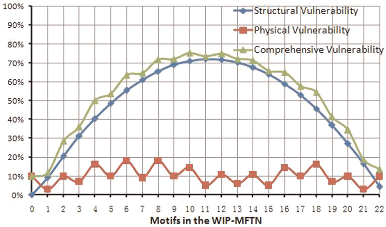
The vulnerability diagram for different motifs in the WIP-MFTN.
From the vulnerability diagram, it is concluded that the network structural properties play active roles in analyzing the comprehensive vulnerability of the WIP-MFTN. As for the structural and comprehensive vulnerabilities, much attention should be paid to the motifs near the middle position. It is noted that these results are well in accordance with the fact. The goal of establishing the WIP-MFTN is to obtain a complete data flow for tracking the material flow in which the workpieces state information is collected by different detecting spaces. Once the RFID devices deployed near the middle position in the material flow do not work, their tracking data will be missed and the corresponding data flow will be interrupted. Therefore, much more attention should be paid to these detecting spaces. Another finding is that the physical vulnerability for detecting spaces has a relatively small impact on the comprehensive vulnerability because RFID technology has developed very rapidly in the past few years and RFID product reliability has been greatly improved. To sum up, all these analysis results will provide a base for raising the WIP-MFTN robustness effectively.
Discussion
The aim of this research is to propose a novel method that can be used to evaluate the RFID-based tracking performance for job-shop-type material flows. The example given in the case study suggests the feasibility and effectiveness of the proposed method. The configuration complexity shows that the RFID-based configuration solution for a WIP material flow is a trade-off between the configuration cost and tracking particle size. On one hand, the smaller tracking particle size will raise higher configuration cost and obtain more accurate tracking data. On the other hand, more RFID detecting spaces will lead to a more complex and unstable structure of the WIP-MFTN. All these issues are described and investigated quantitatively in this article.
At present, there are almost no systemic and reasonable methods in theory for analyzing the RFID-based configuration solution. It is expected that the proposed method will provide practitioners with a holistic perspective of implementing RFID systems. Through the mapping between the event-driven graphical schema and the topology model for WIP material flows, the authors used the CNT to analyze the RFID-based monitoring performance. The advantage of this method is that it is easy to implement and obtain the configuration performance from both macro and micro aspects. From the macro perspective, the statistical properties of the WIP-MFTN (such as the degree distribution, network efficiency, clustering coefficient, and state motif) can be obtained, while from the micro perspective, the physical properties of WIP-MFTN (such as the configuration cost, tracking particle size, growth rate, and vulnerability) can be obtained. The above results will provide a guide for optimizing the RFID-based tracking solution.
However, much attention of this article is paid on the modeling and analysis of a single WIP tracking network. It is expected that much more convincing results can be explored by means of comparing and analyzing the WIP-MFTNs with different tracking particle size for the same WIP material flows. Obviously, this is our research direction in future work.
Concluding remarks
As a powerful communication means, RFID technology has become an important driver in the production and logistics activities of today’s information-based manufacturing industry. Taking RFID-based configuration solution for monitoring job-shop-type material flow as the research object, this article established a WIP-MFTN through the mapping between event-driven graphical schema and topology model. Furthermore, the structural and physical properties of the WIP-MFTN were investigated. The performance was evaluated and the reasonable suggestions for improving the RFID-based configuration solution were given. Based on the above investigation and case study presented in this article, the following conclusions can be made.
The RFID-based tracking procedure of the WIP material flows in a job-shop floor can be described and formulated by the event-driven graphical schema-based operation model. The operations/actions, triggering times, positions, and states of WIP material flows are included in this schema.
The mapping rules between the event-driven graphical schema and the network topology model were investigated. The schema elements were mapped into the network nodes, and the relationships among schema elements were mapped into the network edges. On this basis, an RFID-based tracking network of job-shop-type WIP material flows was established.
A case study for a job-shop-type WIP material flow including four processes shows that the established WIP-MFTN has a small shortest path and a high clustering coefficient. The different schema nodes have the efficient links in this WIP-MFTN.
The research shows that the RFID-based configuration solution is the trade-off between tracking particle size and cost. The more RFID detecting spaces will lead to the more complex and unstable structure of the WIP-MFTN. The analysis for its network-extended property and vulnerability can prove this point.
In the development of this article, two research directions should be paid much more attention. One is to compare and analyze the WIP-MFTNs with different tracking particle size for the same WIP material flow. Further research is to investigate all the material flows in the entire job-shop floor as this work mainly focused on the performance evaluation for a single material flow. In the modern job-shop-type floor, the manufacturing tasks are usually multi-varieties and small batch. And this mixed production mode has resulted in more complex material flows. Therefore, how to investigate the tracking performance from the perspective of the whole job-shop-type material flows is the next research direction.
Footnotes
Acknowledgements
The authors hereby thank both MOST and NSFC of China for the financial aids. In addition, the authors also would like to thank the anonymous reviewers who gave valuable suggestions that have helped improve the quality of the article.
Conflict of interest statement
The authors declare that there is no conflict of interest.
Funding
The research work was supported by both national basic research 973 project (grant no. 2011CB706805) and NSFC (grant no. 71071125).