
Abstract
Since the first applications of computed tomography for medical diagnostics in the 1970s, the technology has been rapidly adopted for non-destructive testing of casted workpieces or complex assemblies. In 2005, the first coordinate measuring machine with computed tomography sensor has been presented for manufacturing metrology and quality control. Today, there exist numerous different manufacturers as the benefits for metrology are convincing. Computed tomography offers the possibility to acquire a measurement object holistically, that is, the whole volume of the object, not only the surface, with a very high point density of typically several millions of points. Current research and development activities are focused on several different aspects of computed tomography. First, the machine components are analysed and improved with respect to application in metrology. Larger detectors with better resolution or X-ray tubes with smaller focal spots may help in improving the machine’s accuracy. Second, algorithms for reconstruction and artefact reduction are developed, especially for metrological purpose. As technical measurement objects feature a greater variety of material properties than in medical diagnostics, different strategies have to be investigated. The most crucial point is that not only the image quality of the radiographies or the reconstructed data is important but also the measurement accuracy plays the decisive role. Finding the interrelation between image quality and measurement accuracy is an important research topic. Third, from a metrological point view, the determination of measurement accuracy and measurement uncertainty for computed tomography measurements is an important task. Methods for experimental and simulation-based uncertainty determination are developed at the time being.
Introduction
Although X-rays have been discovered more than 100 years ago by Wilhelm Conrad Röntgen, their main use was mostly limited to medical applications. Industrial applications were focused on non-destructive testing (NDT). Even Röntgen himself already used X-rays for NDT when he inspected the barrel of his deer rifle. The first ever computed tomography (CT) scanner was realised by Hounsfield and Cormack in 1970 when X-ray-sensitive films could be replaced by an electric X-ray detector. Developments in sensor technology enabled scanning of human heads for cancer diagnostics. After the introduction of the first clinical CT scanner by EMI Laboratories in 1972, more and more applications emerged and led to the first scan of an entire human body in 1976. All systems used Radon’s transformation published already in 1917 1 and even today’s Feldkamp algorithms used for reconstruction still base on Radon’s work.
In the seventies, shortly after the first applications for nondestructive testing, CT was applied for purposes of quality assurance by checking casted parts for blowholes or inner cavities as well as by checking assemblies (with conventionally not accessible features) for the completeness of parts and correct position of the parts. 2 However, it took until 2005 till the first machine designed especially for metrological quality control was introduced 3 (see Figure 1). Today numerous different manufacturers offer machines designed specifically as coordinate measuring machines (CMMs) with CT sensor. CT offers the possibility to acquire a measurement object holistically, that is, the entire volume of the object, not only the surface, with a very high point density of typically several millions of points in relatively short time.
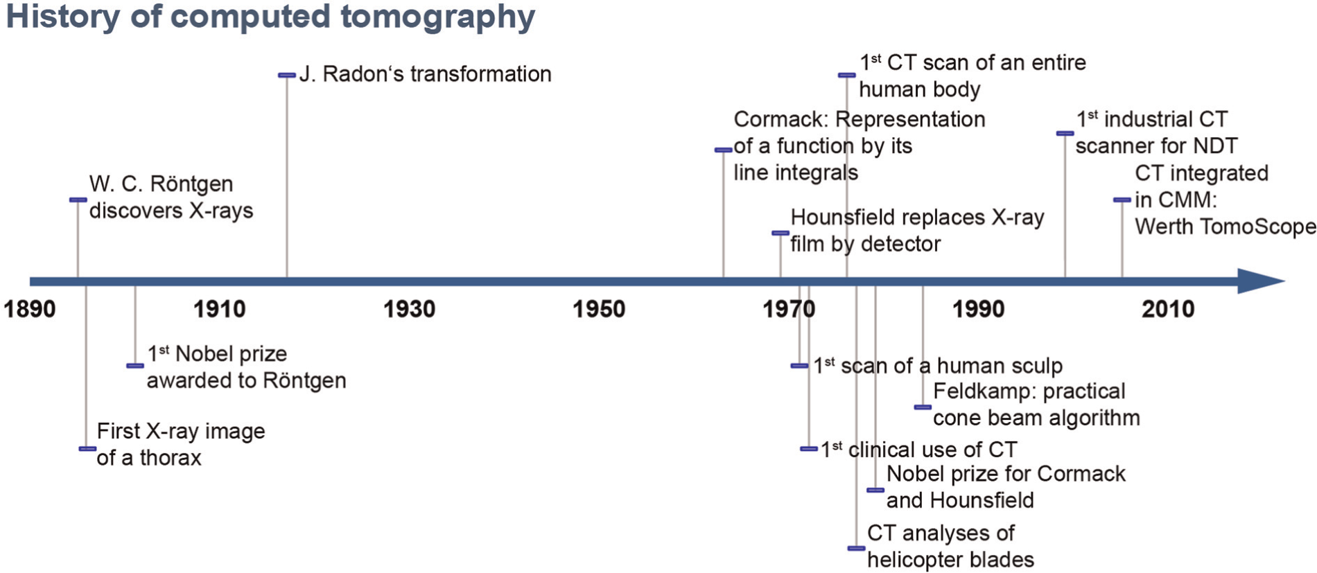
History of computed tomography.
Principle of CT
The basic principle of CT as used for dimensional measurements of geometrical quantities relies on absorption of high-energy radiation. As shown in Figure 2, the X-ray source emits radiation, which passes the measurement object and an X-ray detector captures the remaining intensity. As radiation travels through the workpiece, weakening due to absorption and scattering occurs while X-ray photons interact with the matter of the workpiece.
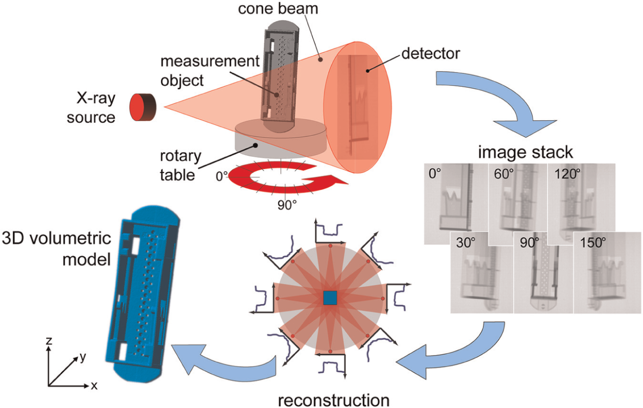
Basic principle of computed tomography in dimensional metrology.
In first approximation, the absorption is proportional to the material thickness d and the absorption coefficient µ, which is dependent on atomic number and density. The remaining intensity I after absorption can be described according to Lambert–Beer’s law:

The X-ray detector measures the absorption in relation to the original X-ray intensity. By measuring the absorption from different angular positions of the workpiece during a rotation of 360°, the volumetric shape of the measurement can be reconstructed.
X-rays are mostly generated by emitting an electron beam and decelerating the electrons with the help of a massive target. The kinetic energy of the electrons is transformed in radiation energy. As different braking effects may occur, different amounts of kinetic energy are transformed in radiation; the emitted radiation spectrum is polychromatic and dependent on the initial energy of the electrons (see Figure 3).
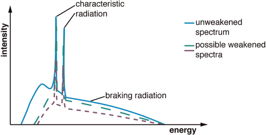
Polychromatic spectrum of X-ray radiation changes due to absorption.
Unlike in medical applications of CT, for technical set-ups, it is possible to change the magnification with respect to the size of the measurement object. It offers the possibility to measure smaller workpieces with higher magnifications, which results in smaller voxel sizes of the reconstructed volumetric data and improved measurement accuracy. According to the intercept theorem, the resulting magnification M may be calculated as shown in Figure 4.
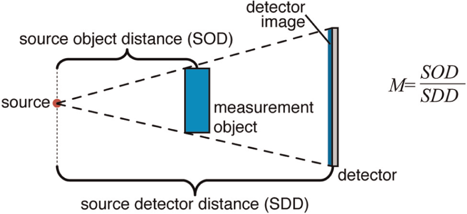
Magnification of the measurement object.
After the acquisition of the projections (radiographic images) of the measurement object, typically 360° around the workpiece, the data have to be reconstructed into a volumetric dataset. In most cases, implementations of Radon’s transformation called ‘filtered backprojection’ are used for the inverse calculation of the path of the rays between each pixel and the radiation source. 1 By overlaying all rays from all projections taken around the measurement object, the volumetric representation of the workpiece is generated (see Figure 5). On the one hand, the number of projections directly influences the quality of the resulting volumetric model and as such the measurement accuracy. On the other hand, it influences as well the necessary measurement time.
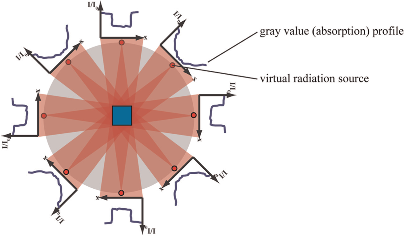
Backprojection for reconstruction of volumetric measurement data.
A rotation of 360° is suitable for rotation-symmetric workpieces or those with nearly similar depth and width. As the aspect ratio gets higher, the X-ray path lengths differ more, and due to the limited dynamic range of the CT system (especially the detector), underexposed or overexposed projections will be recorded. This will prevent reconstruction as a proper ratio I/I0 cannot be calculated. To overcome this limitation, special trajectories for the acquisition and reconstruction of complex-shaped workpieces have been developed. Modern reconstruction technology even offers the possibility of trajectories designed specifically for a workpiece. 4
In order to perform dimensional measurements of geometrical quantities using the volumetric model, the surface of the measurement object has to be defined as all geometrical measurements base on the surface of the workpiece. The simplest method for surface extraction is the calculation of the ISO50% threshold, which is a simple value used for the distinction whether a grey value belongs to the material of the object or represents air. This threshold is calculated via the histogram of all grey values. Typically two peaks are detected: one representing the workpiece material and another one representing the surrounding air. The average of the grey values of the two peaks is the ISO50% threshold. Due to imperfections of the acquisition set-up (e.g. beam hardening, scattering), more accurate methods have been developed to improve the surface determination. They use local and adaptive thresholds instead of a single threshold for the entire dataset: The local grey value profile at the edge of the workpiece is examined, and the surface is determined via the gradient of the profile.
The extracted workpiece surface is the base for all measurements. Like in coordinate metrology, several measured points are fitted to standard geometries, which are used for dimensional evaluations. The difference is the enormous point density that is possible with CT measurements. Typically a dataset consists of several thousands or millions of points.
Accuracy and traceability of CT measurements
To allow manufacturer-independent comparisons of the performance of measurement devices, several characteristics have been defined for conventional tactile CMMs. At the time being, these standards are being adopted for optical CMMs and for CMMs with CT sensor. The German guideline VDI/VDE 2630 5 is currently the standard for specifications of CMMs using CT sensors and hence used as base for the discussions.
Characteristics for performance indication and comparison of CMMs
According to ISO 10360, 6 at first, the probing error may be evaluated. By measuring a calibrated sphere, the deviation of the measured radius Da from the calibrated radius Dr is assessed. This results in probing error form PS

Additionally, the distance of the measured points to the Gaussian fitted sphere is calculated, which means the difference between maximum and minimum distances of the points to the sphere centre is calculated:

The entire measurement sequence typically used for CT measurements, including filtering, number and spreading of measurement points, should be used. For tactile CMMs, typically a pattern consisting of 25 points is used. To receive comparable results for the manufacturer-defined limits, maximum permissible error (MPE) values, the same number of points is required in minimum. As several hundred points are present in CT measurements, the probing error may be optionally specified using these many points.
The length measurement error E, according to ISO 10360, 6 describes the three-dimensional (3D) characteristics of the CMM incorporating the machine itself and the sensor within the entire measurement range. The maximum permissible value for the length measurement error EL (MPEE) is based on measuring distances between two single points on parallel surfaces of the calibrated standard, for example, gauge blocks or step gauges (see Figure 6).
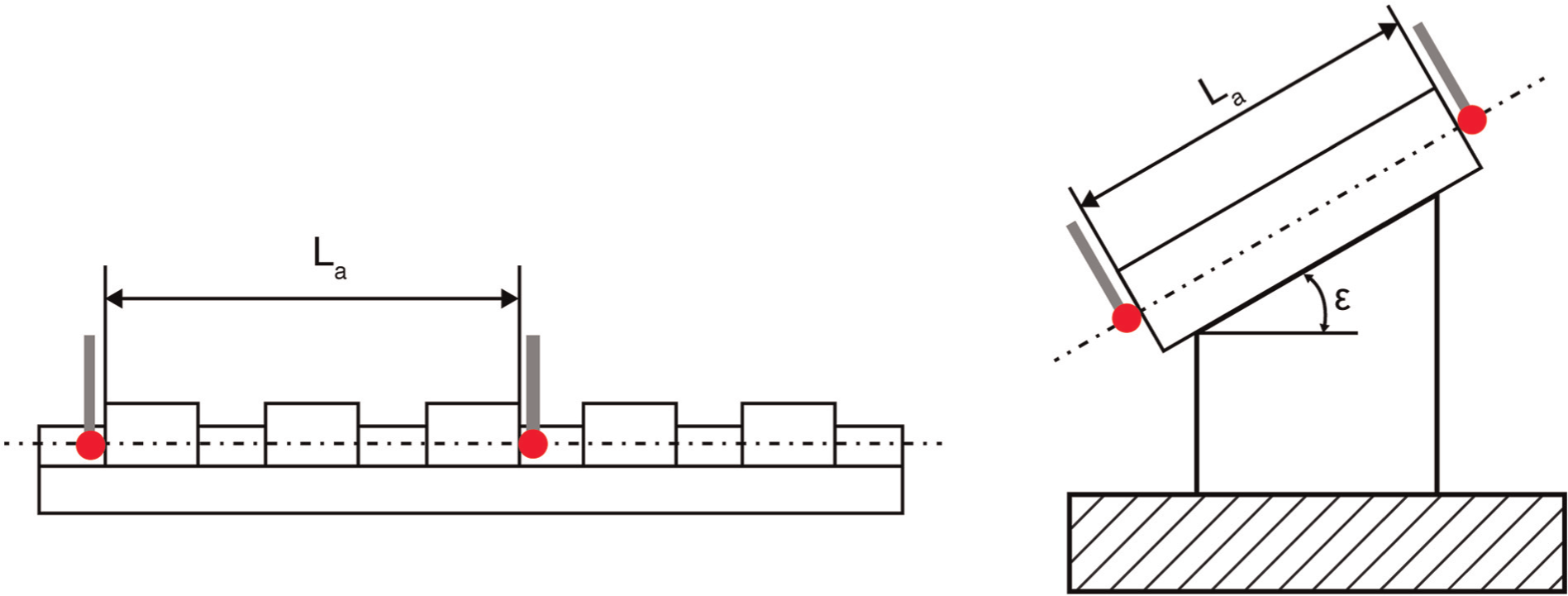
Two-point measurement of step gauge (left) and gauge block (right) for the calculation of length measurement error EL.
The value for EL is calculated via the difference of measured and calibrated distance:

For determining EL in the entire measurement range of the CMM, five independent lengths parallel to the three Cartesian coordinate axes and the four main diagonals should be measured. It is important to distinguish the length measurement error EL from the sphere distance error SD when using calibrated standards such as ball bars, ball or bore plates. Here the distance is calculated between two fitted elements, resulting from probing several points on the workpiece surface (Figure 7). The influence of the probing error is not taken into account properly due to averaging effects of the fitting process. The contribution of the probing error has to be added to allow comparisons against gauge block measurements. There are two possibilities for considering the averaging and the compensation of systematic probing errors.
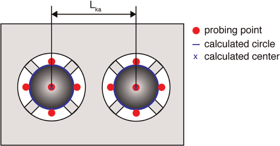
Using a sphere plate to measure length measurement deviation.
The first method uses the results from the determination of PS and PF. If the properties of the calibration standards for measuring SD and PF/PS are similar (in terms of material, size, form, surface), the probing error is assumed as the same for both measurements. E may be calculated by simply adding PF and PS to the value for SD; the sign of the correction term is dependent whether the sum of SD and PS is greater or smaller than zero.
The second method is more accurate but more demanding. It uses an additional gauge block, which is measured in addition to each measuring length. The length measurement deviation EL is calculated as difference between the measured length Lka and its calibrated value Lkr by adding EE of the measurement of the short gauge block. To avoid the influence of single-point probing, it is advisable for both methods to probe the spheres or bores with many points; the probing error is entirely covered by PF and PS.

Especially, for measurements using CT, the influence of workpiece material and geometry, which can be observed as beam hardening or scattering artefacts, is vital (see chapter 7.3). These influences are only partly observed when measuring calibrated standards, in particular, if spherical or cylindrical features are probed. A possibility to estimate the material influence using standards similar to real measurement objects is the use of step cylinders as described in VDI/VDE 2630. 5 Several characteristics (GS, GF, GG) are defined here. If the calibrated standard used for these measurements is similar enough to the actual measurement object under investigation, the influence of the workpiece may be estimated by these characteristics. However, in practice, it will be difficult to judge whether the similarity is enough and the validity of the characteristics is satisfying. It is generally recommended to evaluate the real measurement uncertainty based on measuring calibrated workpieces.
Resolution
The characteristics mentioned above do not indicate anything about the possible structure resolution of the measurement device. The term ‘structure resolution’ describes the ability of the system (the CMM with CT sensor) to transfer a structure (a measurement object) present at the input of the system to the output within definite measurement error limits. Although low-pass filtering increases the probing deviation by suppressing noise of the measurement points, the structure resolution for dimensional measurement gets worse at the same time. Hence this resolution has to be determined and indicated in addition to the characteristics described above.
A clear distinction between the several definitions concerning resolutions has to be made. Spatial resolution is well defined for optical sensors as the axial resolution defining the smallest measurable displacement along the direction of measurement. Structural resolution is defined as the smallest structure measurable with MPE to be specified. In contrast to spatial resolution, it is not included in the error of indication for size measurement and probing error. As low-pass filtering influences structure resolution, the probing error improves while structural resolution deteriorates.
The spatial resolution or structure resolution in voxel grey value domain can be determined according to IEC 62220 7 in radiography via the modulation transfer function (MTF). As not only the interpretation of these values is difficult, the use in CT is limited, as this definition does not cover the entire process of CT measurements. It is obvious that the method to determine the structure resolution has to include the entire workflow used for dimensional CT measurements, that is, especially reconstruction, surface extraction and filtering operations.
The guideline VDI/VDE 2630-1.3 5 describes an understandable method to determine the structure resolution for dimensional measurements of CMMs with CT sensors. The structure resolution for dimensional measurements Dg is defined as the diameter of the smallest measurable sphere. This definition directly indicates the performance of the device to measure small workpieces accurately and does not only indicate a simple perceptibility. As spherical calibration standards are used, the definition of different resolutions for different directions is not necessary. For this determination, a calibrated sphere, for example, a tactile stylus, is used. The measurements of the calibrated sphere have to take into account all parameters and settings typically used for the evaluation of the maximum permissible probing tolerance MPEP (that is the maximum permissible value for the probing error EP) and MPEE values. The structural resolution has to be defined and measured for each magnification; the according values for PS and PF have to be indicated.
It is of vital importance to cover the entire sequence of CT measurements during the determination of the structural resolution. That means structure resolution for dimensional measurements has to be distinguished from structure resolution in voxel grey value domain, which especially does not contain surface extraction. A good structural resolution in voxel grey value domain will have a positive effect on dimensional measurements, but it is not sufficient for good measurement results alone. The definition of resolution solely on the base of the voxel size is not justified; the structure resolution for dimensional measurements will typically be significantly improved.
Limitations of characteristics
As all measurements of characteristics use calibrated standards, which have been manufactured precisely, the influence of the workpiece on the measurement deviations is potentially kept very small. However, in practice, the influence of the workpiece is an important contributor to the deviations observed. As calibration standards are chosen by the manufacturer of the measurement device, cooperative materials will be used. The influence of geometry is minimised. For real measurement tasks in industry, neither the exact material constitution nor the actual shape of the measurement object is known in advance. During the process control, the variation of the workpiece properties will contribute to the observable variance of the measurement results. Additionally the evaluations for performance characteristics are relatively simple. In practice, the measurement strategy will contribute significantly to measurement deviations, especially for complex GD&T evaluations. Hence the accuracy of these measurements cannot be judged by the characteristics mentioned above.
Measurement uncertainty
The only characteristic describing the quality of a specific measurement task is the measurement uncertainty. A complete measurement result consists of a measured value for the task and the attributed uncertainty. The ‘Guide to the expression of Uncertainty in Measurement’ (GUM) describes the fundamentals in determination and expression of the task-specific measurement uncertainty. Here, the uncertainty is defined as ‘parameter, associated with the result of a measurement that characterizes the dispersion of the values that could reasonably be attributed to the measurand’. 8 This definition takes all influences on a measurement result into account, which cause measurement deviations. The five main contributors are the measurement device, the environment, the workpiece, the applied strategy and the operator responsible for the measurement. The contribution of all or at least the major influences has to be covered when expressing the measurement uncertainty. Currently, three possibilities exist to determine measurement uncertainty:
Analytic model according to GUM; 8
Simulation of the measurement process; 9
Experimental determination using calibrated workpieces or standards. 10
Although the formulation of an analytic model is the most accurate method to calculate the measurement uncertainty, it is in practice very difficult and time-consuming to assess all influence quantities and elaborate a mathematical equation. Especially, for non-linear optimisation or filtering algorithms, this principle is hardly possible. In practice, this method will be used only for modelling a limited number of influences and their contribution to measurement uncertainty.11,12
Simulations based on Monte Carlo method may support, but a simulation for CMM measurement using CT sensors similar to the virtual CMM for tactile measurements is currently not available and still in development.13,14 However, it seems quite promising to integrate a simulation in CMM software, which allows the expression of the simulated measurement uncertainty for each measurement task.
At present, the only possibility to estimate the task-specific measurement uncertainty for a specific workpiece and a specific measurement task is the experimental method using repeated measurements of calibrated workpieces.15,16 A reference workpiece similar to the actual measurement objects has to be calibrated using a high point density almost similar to the one used during the CT measurements. Different operators measure this calibrated workpiece repeatedly. The values for each feature are determined and statistically evaluated. Several similar (uncalibrated) workpieces should be measured additionally to take into account the influence of the workpiece (geometry, material, etc.) itself. By statistical analyses, the measurement uncertainty may be estimated by the variance of the measurement values for each measurement task separately. The entire measurement result consisting of value and measurement uncertainty for each feature can be expressed. All evaluations possible by the measurement software are covered, that is, the measurement uncertainty may be determined for all features, even for complex GD&T evaluations.
The indication of the measurement uncertainty is the only possibility to ensure traceability of a measurement result to international standards and the definition of the unit for length measurements, the metre. As traceability serves as a basis for the use of interchangeable parts in modern worldwide mass production, it is essential to express the measurement uncertainty for all measurements.
Application of CT in quality control
The application possibilities of CT in quality control are numerous. Figure 8 shows some examples for the possible range of size and material: light weight plastic connectors, dentures, implants and prosthesis. The largest CTs currently available even offer enough X-ray power to inspect entire aluminium crankcases.
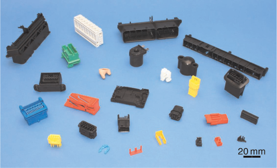
Some examples for workpieces typically inspected using CT.
The workpiece spectrum measurable with a specific CMM with CT sensor depends on the available power of the X-ray tube. As the tube influences the accuracy of the machine, the measurement of smaller workpieces is typically more accurate than for large and high-absorbing objects. Table 1 shows a rough comparison of different tube energies and measurable workpieces.
Values for the orientation for X-ray tube power and maximum material thickness for different types of materials. 3
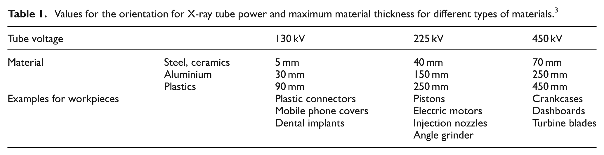
The accuracy, that is, the resulting measurement uncertainty depends a lot on material and geometry of the measurement object. Typical values vary from few microns to some tenths of a millimetre. For example, the measurement uncertainty of diameter and form of orifices of injection nozzles can be measured with uncertainties of 1 µm or less.16,17
CT measurement always starts with an acquisition of the entire measurement object. It is radiated in different views during a 360° rotation. The acquired radiographies are reconstructed to a dataset (‘volumetric model’) representing the entire volume of the measurement object. In contrast to conventional tactile or optical CMMs, measurements are not limited to the exterior surface of the measurement object; it is possible to measure inner or hidden features as well (e.g. undercuts). Additionally virtual cross sections may be used for direct comparisons against CAD data or technical drawings without destroying the actual workpiece. The evaluation of all features defined in CAD model or drawing may be analysed using a single dataset. It is possible to store the data for later analyses, for example, for the evaluation of further features or process control. 18
The main benefit of CT measurements for quality control lies in the necessary inspection time if a large number of features have to be evaluated. Conventional tactile or optical measurements are typically faster if only few and easy accessible features have to be inspected. As CT measurements always need the acquisition of the entire workpiece with a volumetric model, the more features are measured, the smaller the time needed per feature gets (see Figure 9). As a result CT measurements have enormous advantages in first sample inspection, and the CT data may be even stored as retain sample and used for controlling the production process.
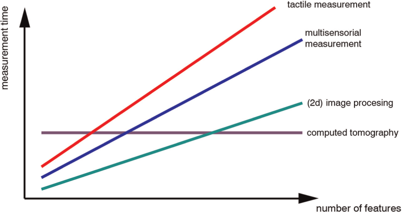
Necessary measurement time for different sensors in dependence of number of measured features (based on Werth Messtechnik, Giessen, Germany).
As Table 1 shows workpieces may consist of different materials and may have complex shape. Limitations occur when several materials have to be measured at once, for example, for plastic connectors with metal inserts. Due to the limited dynamic range of the CT system, combinations of high-absorbing (metal) components and low-absorbing (plastic) components at once are only hardly possible. Current research work tries to overcome this severe limitation for the measurement of complex components or assemblies by multi-energy measurements: 19 The acquisition of measurement data is repeated with different measurement parameters. The high-energy measurement allows the acquisition of high-absorbing parts and a lower-energy measurement the acquisition of low-absorbing parts. The data from both measurements are combined in one multi-energy dataset that is used for subsequent dimensional evaluation. Future work will automate this approach and ensure traceability of these measurement results.
Conclusion and outlook
The application possibilities of CT in quality control are numerous. Current research and development activities are focused on several different aspects of CT. First, the machine components are analysed and improved with respect to application in metrology. Larger detectors with better resolution or X-ray tubes with smaller focal spots may help in improving the machine’s accuracy. Second, algorithms for reconstruction and artefact reduction are developed especially for metrological purpose. As technical measurement objects feature a greater variety of material properties than in medical diagnostics, different strategies have to be investigated. The most crucial point is that not only the image quality of the radiographies or the reconstructed data is important; the measurement accuracy plays the decisive role. Finding the interrelation between image quality and measurement accuracy is an important research topic. Third, from a metrological point view, the determination of measurement accuracy and measurement uncertainty for CT measurements is an important task in order to guarantee traceability of measurements. Methods for experimental and simulation-based uncertainty determination are developed at the time being.
Footnotes
Declaration of conflicting interests
The authors declare that there is no conflict of interest.
Funding
This research received no specific grant from any funding agency in the public, commercial or not-for-profit sectors.