
Abstract
This article proposes a novel separable field shaper design for electromagnetic sheet impact forming. The efficiency of the field shaper under different geometric parameters was evaluated through a combination of the Taguchi method and three-dimensional coupled simulation. The deviation in impact velocity between the experiment and the simulation was under 3%. The results indicate that the slit feature determines the performance of the field shaper. Wider slits reduce the energy loss resulting from electromagnetic repulsion. In addition, with more field shaper components, the generated magnetic pressure will be distributed more evenly. Based on the analysis result of the nonsymmetric edge effect, some guidelines for designing the field shaper are proposed.
Keywords
Introduction
Electromagnetic forming (EMF) is a high strain rate forming process exhibiting significant advantages, such as increasing the formability of material, improving the springback of aluminum alloy, and embossing a holographic image on sheet metal.1–3 Because of the particular advantages, EMF achieves a better forming result for complicated geometry that is difficult to form by conventional forming processes. For example, Kamal et al. 4 successfully embossed a holographic optical diffraction grating image on sheet metal using EMF.
In the EMF process, the field shaper is a practical tool to help concentrate the magnetic flux and efficiently prolong the service life of the coil. Using the field shaper can change the Lorentz force distribution in an economical way without designing a special coil for different applications, thereby carrying out batch production more easily and improving the flexibility of EMF. Although the field shaper plays an important role in EMF, application of the field shaper is still not popular, especially in electromagnetic (EM) sheet metal forming. This could be attributed to the complexity of the transient variation in the EM field. Beerwald 5 and Yu et al. 6 studied the influence of the field shaper in tube forming. They noted that the field shaper significantly changed the magnetic field distribution. These two studies were based on two-dimensional (2D) simulation results, so some edge effects in real geometries could not be considered. Recently, many researchers used three-dimensional (3D) simulation to examine the EM field distribution of EMF.7–9 Psyk et al. 8 described the development of numerical approaches and implied that accurate 3D simulation could be achieved due to the recent progress of the finite element method. Mamalis et al. 10 and Bahmani et al. 11 indicated that the magnetic pressures applied on the workpiece under the slit feature are reduced. Bely et al. 12 used a special field shaper to adapt a cylindrical compression coil and form a sheet metal workpiece. Chu et al. 13 used a field shaper to assist in the free impact sheet forming process. Up to now, the variation in EM field caused by the field shaper has rarely been discussed, and the quality of the field shaper for sheet forming strongly relies on personal experience.
This article proposes a new separable field shaper design for EM sheet impact forming. 3D coupled simulation software has been adopted to analyze the EM field, and the Taguchi method is employed for the design of experiments (DOEs) to optimize the design parameters. Through the 3D simulation process, the nonsymmetric edge effects in geometry performed in the magnetic force distribution have been calculated, and the influence of each geometric parameter in designing the field shaper has been clarified. As a result, some simple guidelines and an optimal design for the field shaper will be proposed. With the design guidelines, the industrial application of EMF could be expanded and the cost of engineering manufacture could be decreased.
Theoretical background
After the capacitor discharges high-voltage electricity, a transient magnetic field surrounding the coil and the field shaper generates an eddy current on the surface of the field shaper, which is a concentrator and can help to uniformly distribute the Lorentz force. Due to the slot design in the field shaper, the eddy current flowing on the lower surface of the field shaper is blocked and forced to flow to the upper surface of the field shaper. The current flow produces variations in the magnetic field. Then, the temporarily varying magnetic field generates another eddy current in the workpiece. With the losses of inductive energy during the inefficient inductive coupling of the coil, field shaper, and workpiece, the secondary induced eddy current was of lower energy than the case without the field shaper. From the viewpoint of the system, the system with the field shaper entails additional resistive losses and energy losses due to additional gap volumes. Nevertheless, as soon as the secondary induced eddy current flows through the workpiece under a shielded magnetic field, the EM field exerts the Lorentz force, which pushes the workpiece toward the conical punch.
Physics foundation
The induced Lorentz force
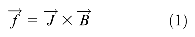
where
where
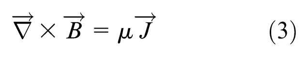
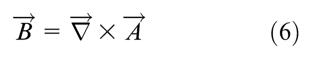
In the analysis of EM field, the magnetic vector potential
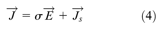
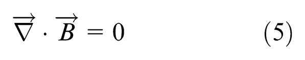
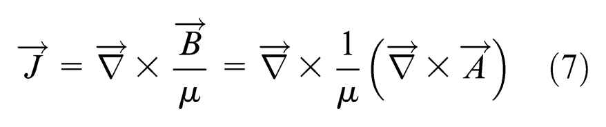
Hereafter, the induced total current
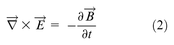
Moreover, the electric field expressed in equation (2) is given as
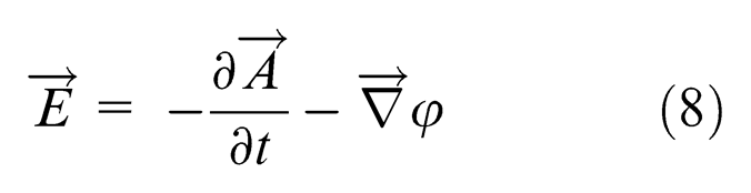
where
Experimental design
A free impact forming experiment was established to examine the influence of different field shaper designs performed in the magnetic field. Based on the physical characteristics that a higher flying velocity represents a stronger Lorentz force, a high-speed camera was applied in the experiment to measure the flying velocity of the workpiece. During the free impacting process, the freely flying workpiece was recorded by a high-speed camera (Phantom V7.1; Vision Research, Inc.) taking pictures with a time interval of 70 µs. Through simple calculation, the velocity of the flying workpiece could be retrieved. Figure 1 illustrates the experimental setup.
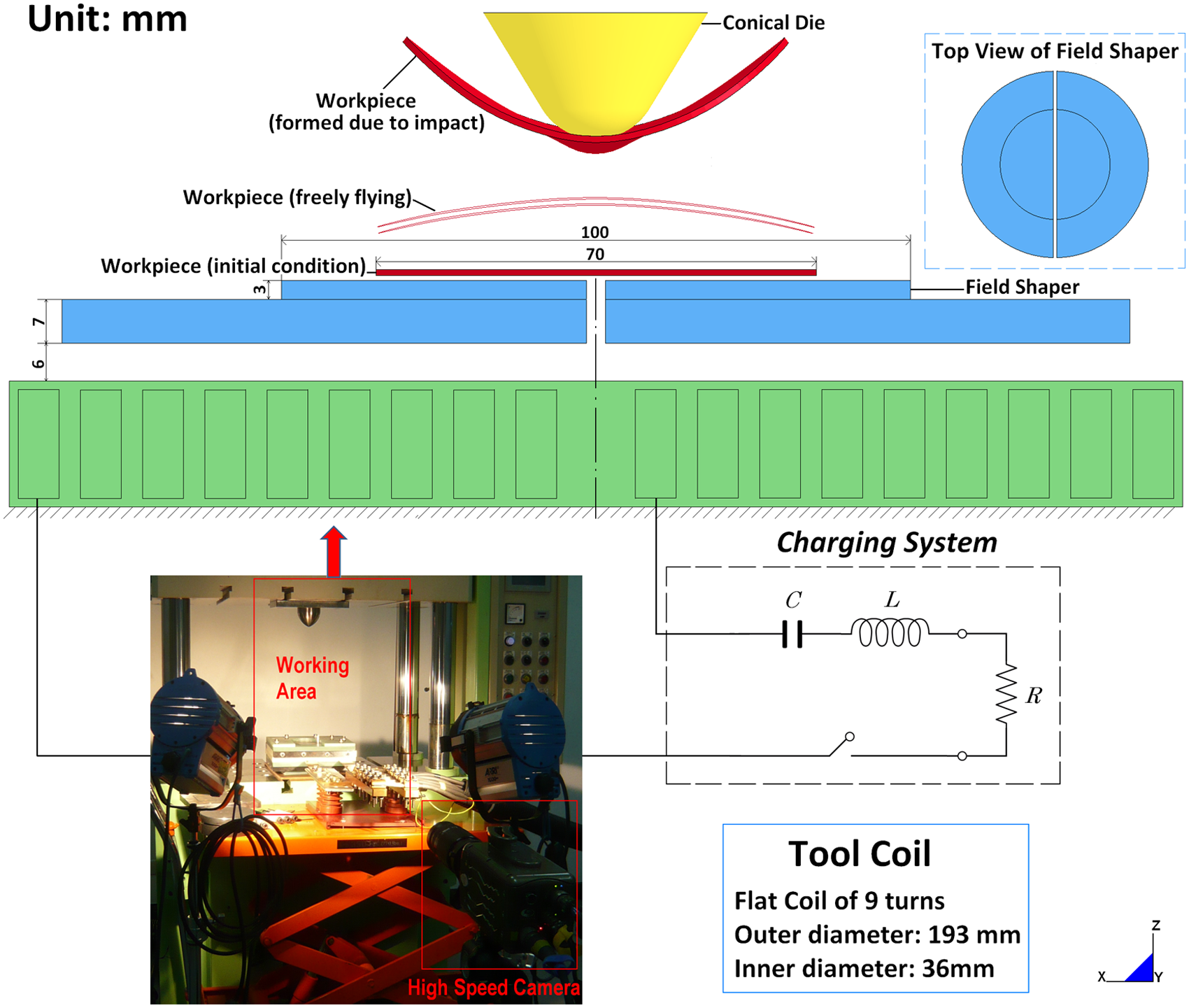
Experimental setup.
Note that the material EM characteristics dominate the efficiency of the field shaper. The material with higher electrical conductivity can reduce the energy loss through the inducing process. Therefore, the field shaper and the coil were made of copper, and the workpiece is aluminum alloy AA 6061-T6. The diameter of the aluminum sheet is 70 mm and the thickness is 1 mm.
Novel design of field shaper for EM sheet metal forming
In the EM sheet metal forming process, the flat coil is the most common approach due to its simple design. However, the pressure allocation in the forming zone generated by a flat coil is uneven, resulting in nonhomogeneous deformation of the workpiece. Therefore, controlling the distribution of the force and reducing the disadvantage of an inhomogeneity in the force distribution are the primary targets in designing a field shaper.
Design concept
The function of the field shaper is to change the EM field and form an ideal pressure allocation, so the direction of eddy currents must be considered. Due to the skin effect, the induced eddy current only flows on the surface of the field shaper. Considering the direction of the eddy current, the slit feature was designed to interrupt the original current loop and force it to flow from the bottom surface to the top surface and form a new magnetic field. Accordingly, a separable field shaper with different slit types is proposed in this article, as illustrated in Figure 2. The separable field shaper was adapted to the flat coil. To avoid energy loss, the diameter of the bottom surface is set to fit the geometry of the flat coil.
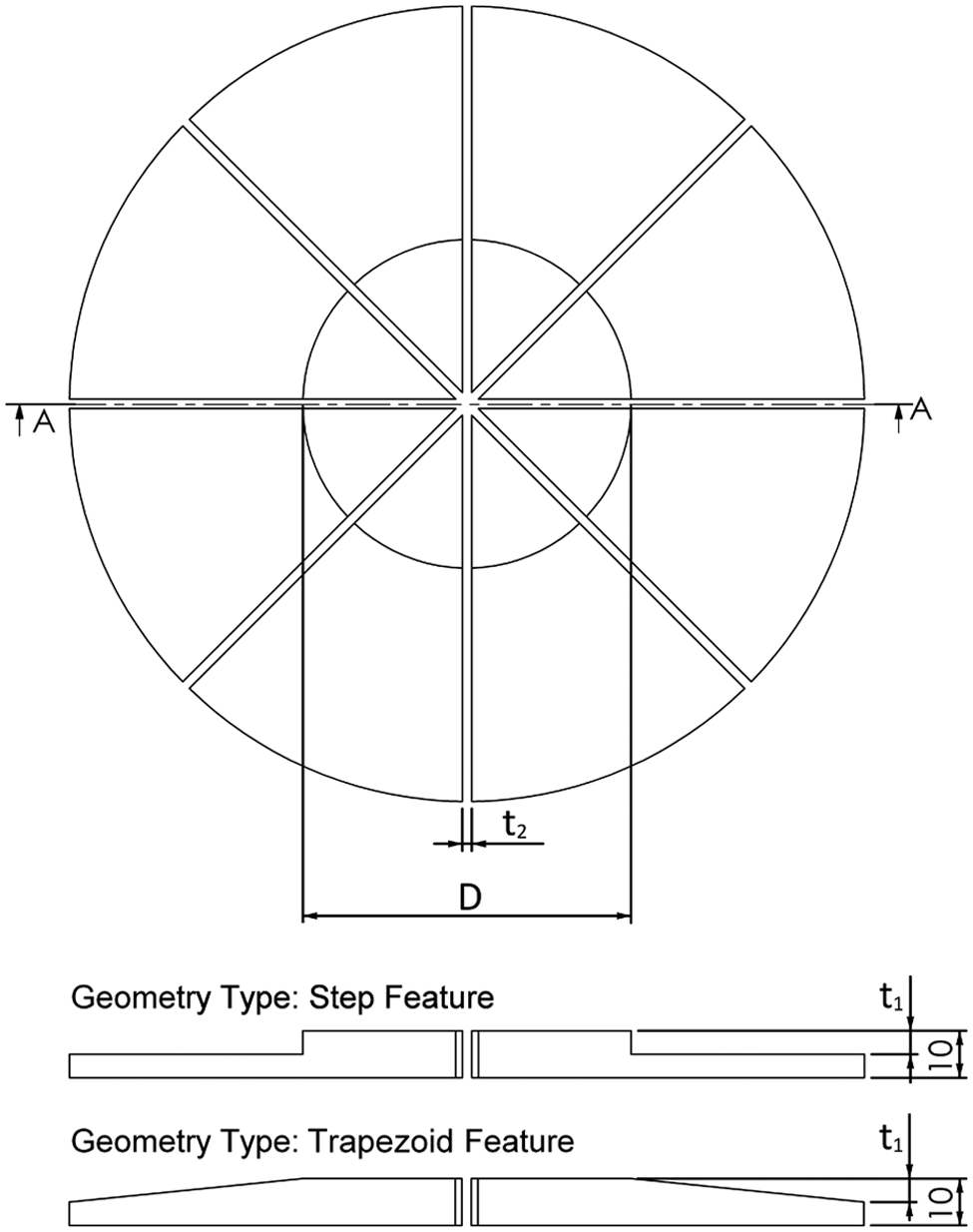
Design of the separable field shaper, with eight assembling parts
Parameter analysis of field shaper design
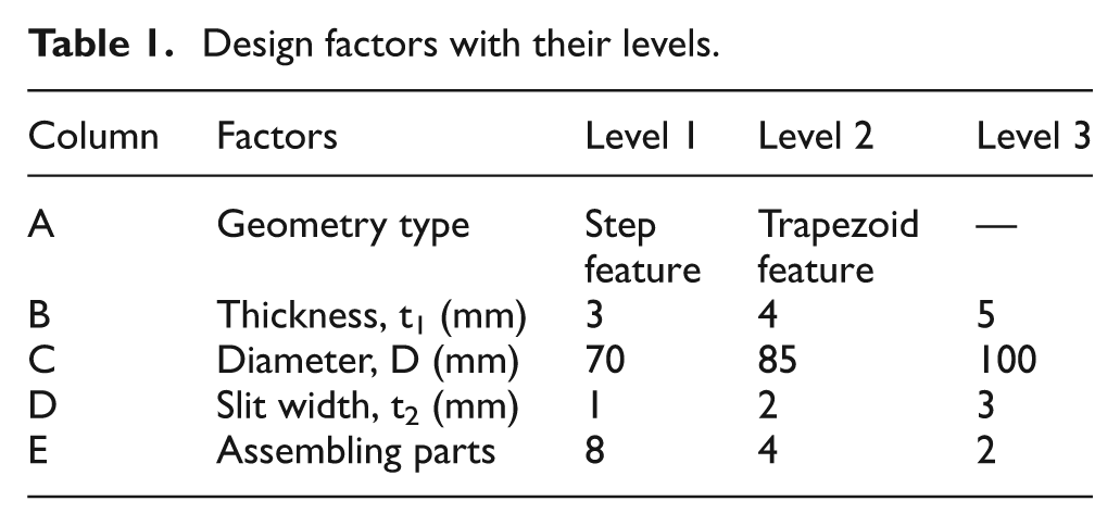
The design and assembling parameters such as geometry, slit width, assembling type, and dimension were analyzed using the Taguchi method. The Taguchi method is an engineering approach to achieve a state of robustness in the manufacturing process or product. Through special design of orthogonal arrays introduced by Dr. Taguchi, only a small number of experiments are needed to obtain the optimum setting of process parameters. Moreover, the factors with different levels could be analyzed by choosing appropriate orthogonal arrays, increasing the feasibility of the experimental design. This method has been widely employed in industry and academic researches.16,17 An L18 orthogonal array with one parameter in two levels and four parameters in three levels was used in this study, as given in Table 1. With the Taguchi method, computational expense was reduced from 162 times to 18 times. Therefore, only 18 experiments were required to calculate the influence of each parameter for obtaining the optimal parameter design of this field shaper.
Design factors with their levels.
Numerical simulation
EMF is a high-speed forming process in which deformation of the workpiece is completed within a few hundred microseconds. Under this premise, temporary variation in the EM field is difficult to measure or observe. Accordingly, a useful and practical tool, simulation software, was employed to study the change of the EM field in detail. Since a noncoupled simulation is unable to present the actual Lorentz force distribution, 18 coupled modeling software is an essential tool to provide an accurate analysis result. A 3D coupled mechanical–thermal–EM simulation software, LS-DYNA_EM module, was applied in this article to explore the edge effects of different field shaper designs.
The coupled simulation computes the configuration of the EM field under each step of time increment. A boundary element method is derived into the LS-DYNA_EM module
15
to avoid the meshing problem associated with air. Equations (1) and (6) to (8) are solved in terms of
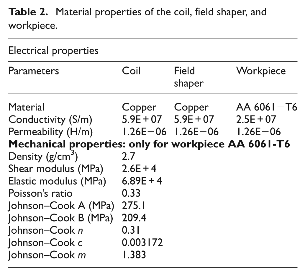
Material properties of the coil, field shaper, and workpiece.
To be able to simulate the magnetic field distributions, the charging current that flows through the coil was measured by the Rogowski coil as given
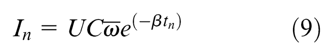
where U = 1.8 kV is the initial discharge voltage, C = 690 µF is the total capacitance of the capacitor bank, β = 2265 s−1 is the damping exponent, and ω = 27497 rad/s is the angular frequency. Due to the characteristic of pulse discharging system used in the EMF process, the value of pulse current is varying with the discharging time. Moreover, the measuring principle of the Rogowski coil is based on Ampère’s law, and the voltage induced in the coil is proportional to the change rate of the charging current. Therefore, the proportion is calculated from equation (9) and is derived into measured voltage to obtain the real charging current. The waveform of measured raw data is similar to the sinusoidal shape and thus resulted in the corresponding waveform of calculated current, as shown in Figure 3.
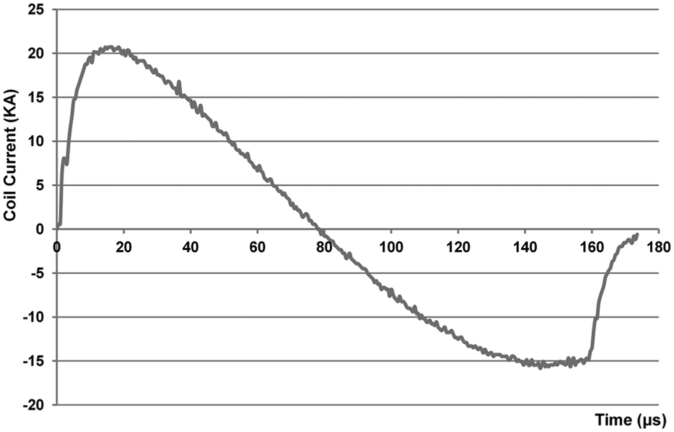
Waveform of coil current.
The setting of the simulation model was based on the experimental setup, as plotted in Figure 1. Since the coil and field shaper are fixed in the experiment, only the deformation of workpiece is taken into consideration. The flow stress of workpiece is established based on the Johnson–Cook model due to the process characteristic of high impact velocity. The Johnson–Cook model is expressed as
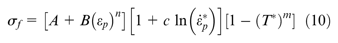
where
Results and discussion
In a free impacting process, a good field shaper design performs with better efficiency and more uniform distribution of Lorentz force, resulting in a higher flying velocity. Hence, the impacting velocity was used to determine the quality of the field shaper design.
Comparison between experiment and simulation
The Lorentz force decays along with the increasing distance between the field shaper and the moving workpiece. The fully coupled analysis method calculates the instant variation in the EM field caused by the moving workpiece. It implies that the fully coupled simulation result performs a more accurate flying velocity of the workpiece without overestimation. Displacement of the workpiece during the free flying status is plotted in Figure 4 and compared with the simulation data. The comparison reveals good agreement between the experiment and simulation, with the deviation of impacting velocity between them being under 3%. It is shown that the calculated flying velocity is larger than the experiment. The result is probably caused by the joule heat generated in the coil and the field shaper. The experiment was done at room temperature, however, with an increase in the discharge number of the experiment, and the temperature of the coil and field shaper slightly increased. Moreover, the spotlight used to assist the high-speed camera may also cause the temperature to rise in the coil and field shaper. The higher temperature leads to lower electric conductivity, resulting in the deviation between the experiment and simulation.
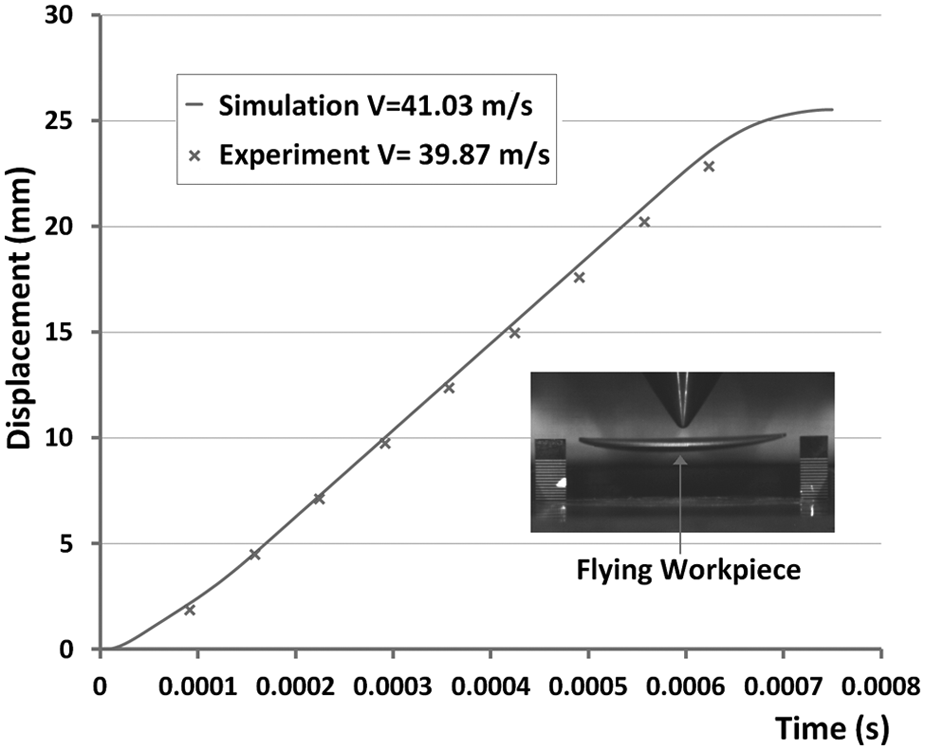
Experiment and simulation results of the displacement, measurement and calculation respectively.
Parametric effects on field shaper design
Since the simulation result shows good agreement with the experiment, calculated results such as velocity and Lorentz force distribution could be assumed to be accurate data and applied to evaluate the field shaper design.
Table 3 shows the layout of the simulation and impacting velocity of each test under different conditions. Figure 5 plots the signal-to-noise ratio (SNR) graph calculated from Table 3. The SNR graph shows that the optimal combinations of the geometric parameter levels would be A2B1C1D3E1, with an impacting velocity of 63.02 m/s. Through the optimal design of geometric parameters, the field shaper could provide almost three times the impact velocity of the worst design of test No. 9, which induces an impact velocity of 22.98 m/s.
Simulation layout using an L18 orthogonal array and results.
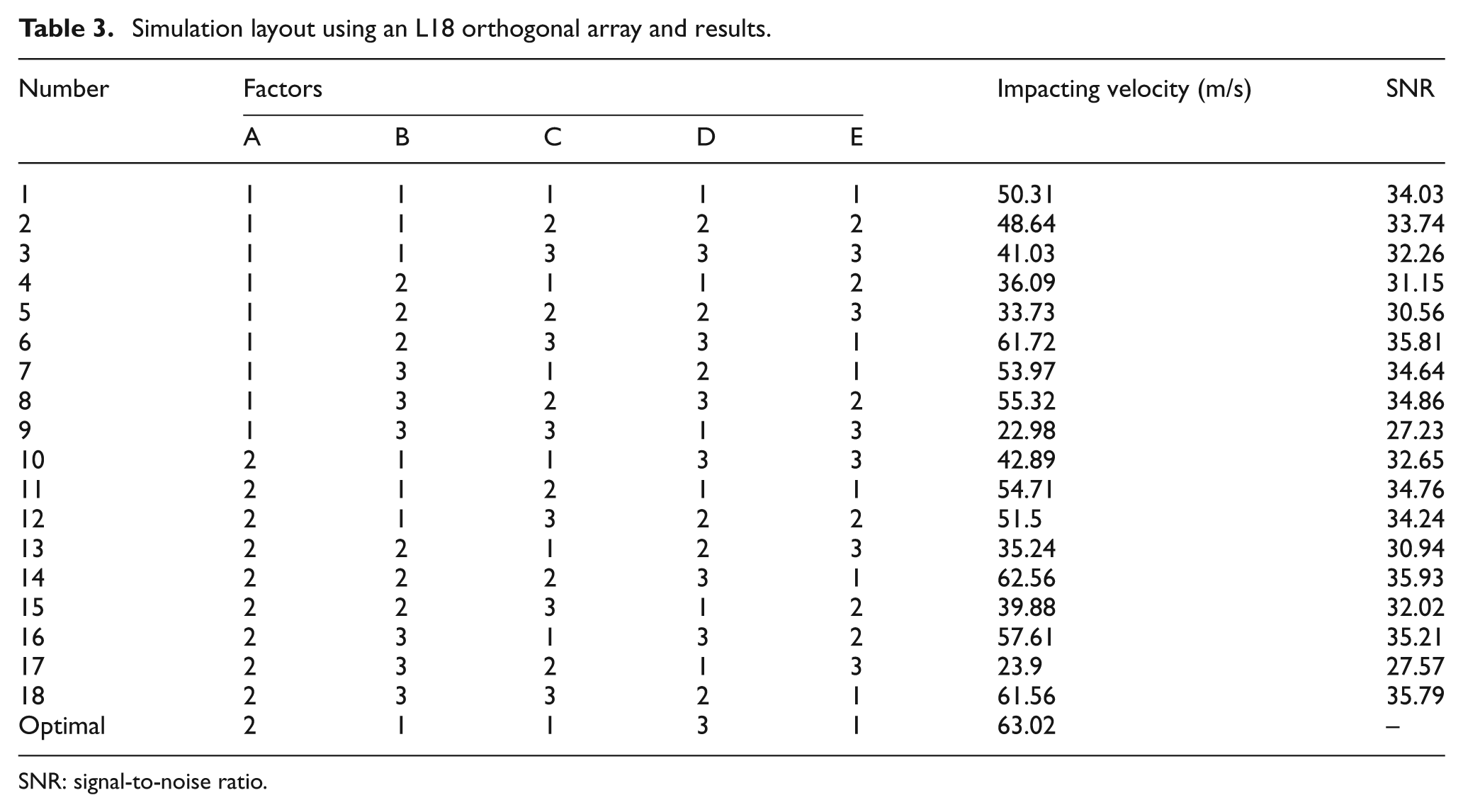
SNR: signal-to-noise ratio.
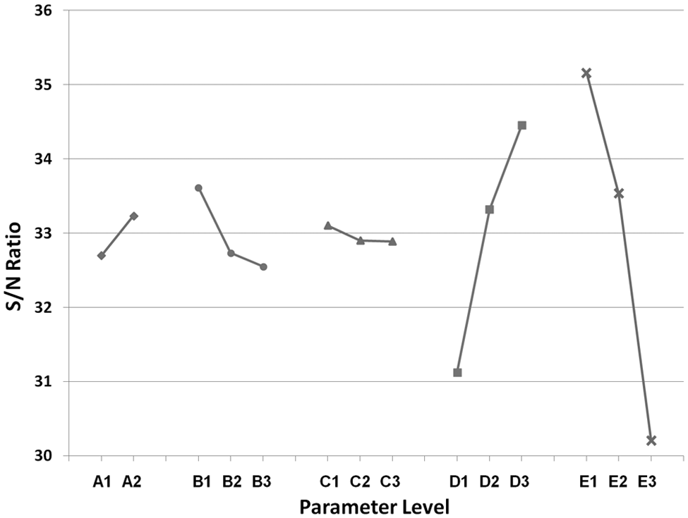
SNR graph for the field shaper design.
According to the SNR analysis demonstrated in Figure 5, the widths of the slit between each of the parts of the field shaper and the number of components have significant roles in the field shaper design. It has been noted that almost no Lorentz force was applied on the workpiece around the slit region. 11 However, the contrasting result in the SNR graph shows that a wider slit provides higher impact velocity. The reason for this contradiction is due to different workpiece geometries. The purpose of the design of the slit feature is to lead the current to flow to the expected position and then generate a uniform magnetic pressure distribution. Differing from the field shaper design for tube forming, the slit feature in the field shaper for sheet forming interrupts the continuity of the current and forces the turbulent current to flow through the slit region. Therefore, a strong magnetic field was generated around the slit region, as the induced eddy current. The interaction between the induced eddy current and the magnetic field generated the corresponding Lorentz force distribution, which performs at higher force at the end region around the slit feature. The distribution of the surface current, magnetic field, and Lorentz force of the Taguchi test No. 3 is demonstrated in Figure 6. The current density and magnetic field around the slit feature are stronger than other regions, resulting in corresponding Lorentz force distribution.
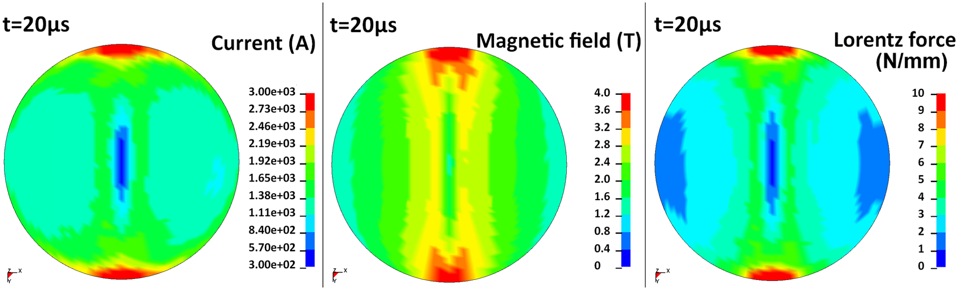
Distribution of surface current, magnetic field, and Lorentz force of Taguchi test No. 3.
As previously described, the slit feature of field shaper for sheet forming performs the contrast Lorentz force distribution with the same feature for tube forming. This phenomenon indicates that the design rules of a field shaper for tube forming cannot be applied to the design for sheet forming. Further investigation of the field shaper for sheet forming is necessary and valuable for industrial applications.
Since the slit feature of the field shaper shows significant influence in the construction of the EM field, the width of the slit is another point needing to be considered. Based on the analysis of the SNR graph, a wider slit performs more efficiently. The eddy current flow on either side of the slit is in the opposite direction, leading to an EM repulsion between each assembling part of the field shaper. Therefore, the field shaper will be split from the slit region. As a result, energy consumption increases with a decrease in the width of the slit.
As stated earlier, the effect of EM repulsion caused by the slit feature between each assembling part of the field shaper has been clarified. To see the variation in EM field under different slit widths, the geometric parameter levels were controlled as A2B1C1E1., with the width of slit varying from 1 to 6 mm, as drawn in Figure 7. The result shows that the field shaper is more efficient with a slit range from 3 to 4 mm. In addition, the impact velocity of the slit width above 3 mm descends while the slit width increases. The wider slit improves the energy consumption from EM repulsion between each assembling part of the field shaper. However, the wider slit also increases the region of weak Lorentz force distribution, which is located above the slit region, as shown in Figure 6. Combining the interaction between EM repulsion and Lorentz force distribution, an optimal width of slit can be determined through preliminary evaluation.
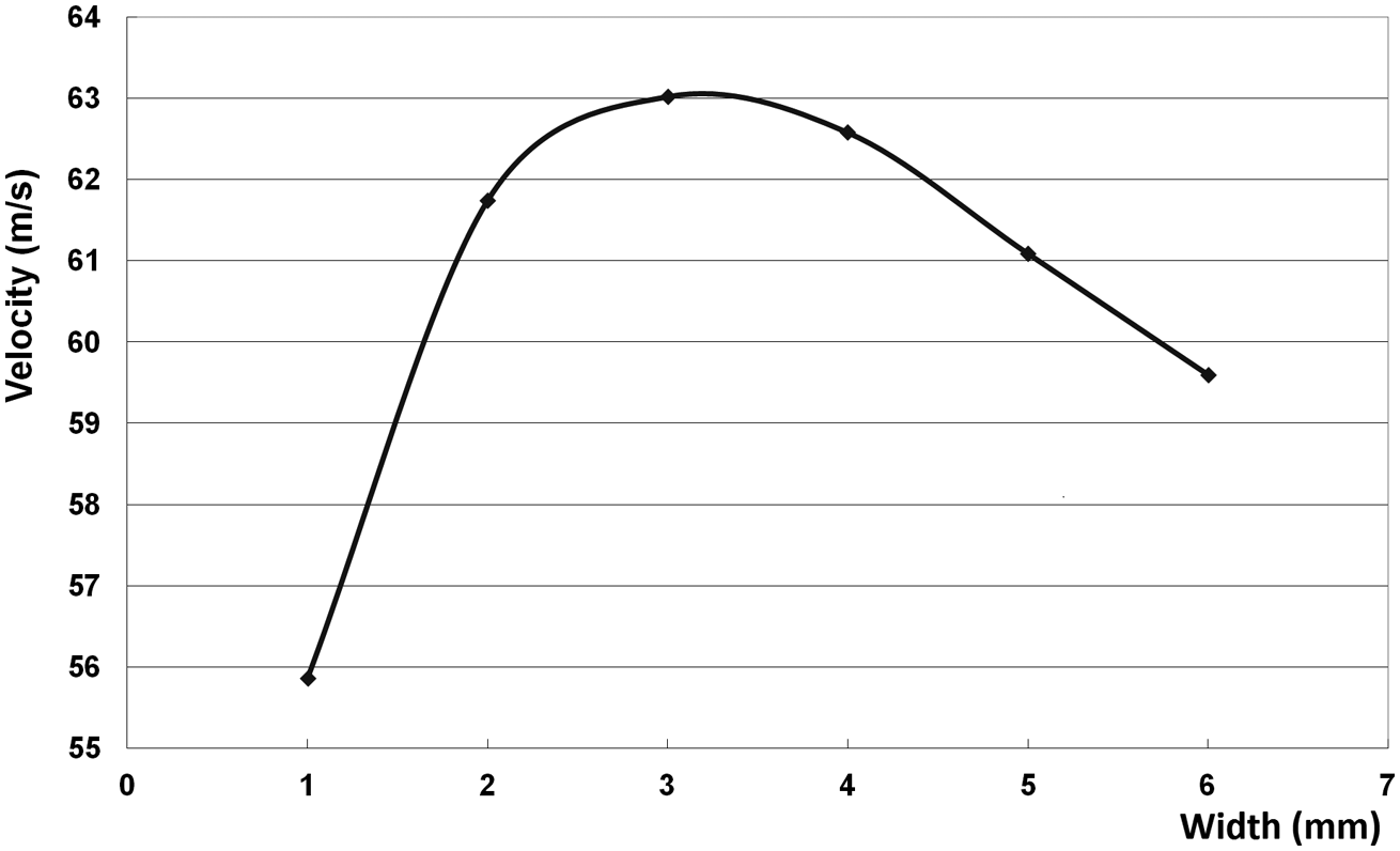
Impact velocity under different slit widths.
Based on the uneven force distribution produced on the end region around the slit feature, the stress state of the workpiece is dominated by the number of components of the field shaper. Figure 8 plots the different Lorentz force distributions with the assembling parts of 2, 4, and 8. It shows that only two local regions of the workpiece were applied force while the field shaper was made by two components. However, the force was dispersed in eight regions while the field shaper was made by eight components, which improves the stress state applied on the workpiece. Consequently, the field shaper with more components provides more balanced force distribution, resulting in higher impacting velocity.
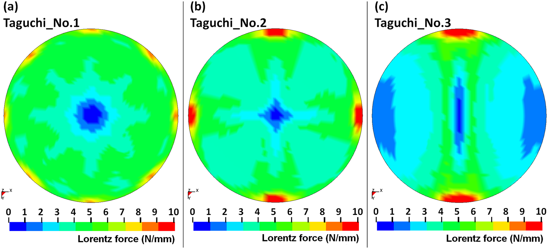
Lorentz force distribution under different numbers of assembling parts, at t = 20 µs: (a) 8 parts, (b) 4 parts, and (c) 2 parts.
According to the results of analysis, the EM force could be applied to the desired region by designing the slit feature. In addition, by adjusting the geometrical parameter, the field shaper could achieve optimal efficiency and provide ideal forming results in industrial application.
Guidelines for optimal field shaper design
According to the results of analysis, the slit feature in a field shaper determines the performance of the entire process. Here, some guidelines for optimal design of the field shaper for EM sheet metal forming are suggested in the following:
The slit feature is a necessary design of the field shaper to guide the induced current to flow to the expected region.
The Lorentz force will be concentrated at the end region around the slit feature. Hereafter, the slit feature design will control the distribution of the Lorentz force.
The eddy current flowing on the opposite side of the slit is in a reversed direction, leading to EM repulsion between each component of the field shaper. As a result, the wider slit feature reduces energy loss.
The region of the workpiece above the slit feature receives less Lorentz force than the other part around the end region of the slit feature. Hence, an optimal slit width must be determined by considering the interaction between EM repulsion and the Lorentz force distribution.
A field shaper with more components provides more homogeneous force distribution, contributing to higher impact velocity.
Conclusion
This article uses the Taguchi method and 3D simulation to evaluate a novel field shaper design for the sheet impact forming process. The results of analysis reveal the influence of each geometric parameter of the field shaper design with a minimum number of experiments. The design and evaluation procedure used in this article reduced the development time.
Moreover, this article proposes an optimal design of field shaper for sheet impact forming. The distribution of Lorentz force implies that the slit feature of this field shaper concentrates the Lorentz force on local regions of the workpiece. This phenomenon makes it possible to control the distribution of magnetic pressure by designing the geometry of the field shaper. Through the analysis of the SNR graph, the most significant parameters were discovered. The width of the slit between each component of the field shaper and the number of components are the main parameters affecting the value and distribution of magnetic pressure owing to the change in magnetic field resulting from the slit feature of the field shaper. Based on the results of analysis, some simple guidelines for field shaper design to estimate the maximum impacting velocity are derived.
Footnotes
Acknowledgements
The authors would like to thank the Metal Industries Research & Development Centre (MIRDC) for supporting this research study by providing the Magnetic Pulse System.
Funding
This research received no specific grant from any funding agency in the public, commercial, or not-for-profit sectors.