
Abstract
Magnetic pulse welding is a high-speed welding technology, which is suitable for welding light metal materials. In the magnetic pulse welding system, the field shaper can increase the service life of the coil and contribute to concentrating the magnetic field in the welding area. Therefore, optimizing the structure of the field shaper can effectively improve the efficiency of the system. This paper analyzed the influence of cross-sectional shape and inner angle of the field shaper on the ability of concentrating magnetic field via COMSOL software. The structural strength of various field shapers was also analyzed in ABAQUS. Simulation results show that the inner edge of the field shaper directly affects the deformation and welding effect of the tube. So, a new shape of field shaper was proposed and the experimental results prove that the new field shaper has better performance than the conventional field shaper.
Introduction
With the world’s rising attention on environmental protection, a series of green manufacturing technologies have been developed rapidly. 1 Magnetic pulse welding (MPW), as an application branch of electromagnetic forming technology, is a solid-state welding technology. 2 The MPW can convert electrical energy into the kinetic energy of the metal workpiece, enabling the two materials collide at a high speed to achieve metallurgical bond. 3 The collision velocity usually varies from 200 to 500 m/s, and the welding process is very short (only tens of microseconds). 4 With the exception of good controllability and repeatability, MPW technology is also suitable for welding materials with poor weldability. 5
A 6060 series aluminum alloy has the characteristics of light weight, high strength, and corrosion resistance, so it is widely used in automobile, aerospace, electrical and other industries.6,7 However, this type of alloy has a high melting point due to the existence of an oxide film, and oxides are easily incorporated into the welding area. 8 When traditional fusion welding is used, it is easy to form a brittle reaction layer at the interface, resulting in a decrease in the strength of the joint.9,10
So far, several methods of welding aluminum alloys have been studied, such as explosion welding, friction stir welding, and MPW. However, friction stir welding is only applicable to the plate welding, and the welding efficiency is very low. 11 The mechanism of explosive welding is similar to that of MPW, but its energy comes from explosives, so the welding process has poor controllability. 12 On the contrary, MPW can avoid these shortcomings, and there are fewer intermetallic brittle compounds in the welding interface.
MPW is mainly divided into tube welding and plate welding. The plate welding mainly uses single-turn coils. 13 For the tube welding, a field shaper (FS) is usually added between the multi-turn coil and the tube. The FS can not only concentrate the magnetic field and increase the electromagnetic force in the welding area, but also increase the service life of the coil.14,15 Therefore, the structure of the FS is one of the main research contents in the field of MPW. However, most researchers have been devoted to finding ways to improve the welding efficiency of the FS, ignoring its structural strength.
Rajak et al. 16 used LS-DYNA to simulate and analyze three types of FSs namely single-step FS, double-step FS and tapered FS, and found that the efficiency of single-step FS is better than double-step and tapered FSs. Zhang et al. 17 proposed a new FS for spot welding. Through the co-simulation of COMSOL and ANSYS, it was found that the FS with a gradual central aperture can increase the electromagnetic force on the welding area. Fan et al. 18 studied the cladding effect of bimetallic tubes by changing the inclination angle of the FS. The results show that adjusting the inclination angle is more effective than shortening the feed length in improving the incongruous plastic deformation. Khan et al. 19 analyzed the influence of the coil and FS materials on magnetic pressure in the ANSYS Maxwell environment. They found that the combination of single-turn Gu coil and Be FS or multi-turn SS coil and Gu FS can produce the largest magnetic pressure. Chu and Lee 20 designed a separable FS for electromagnetic forming. They pointed out that increasing the width of the gap can reduce the energy loss caused by electromagnetic repulsion. With the increase of the FS components, the magnetic pressure distribution became more uniform.
In this paper, the primary purpose is to ensure that the FS has considerable stability when its magnetic collecting capacity is improved. In order to facilitate the optimization of the FS, the three-dimensional finite element model, which was used for electromagnetic field analysis, was established based on the working principle of MPW in the first step. Subsequently, the influence of the cross-sectional shape of the FS on the magnetic flux density was analyzed in the simulation environment, the objective of which was to find the geometric parameters that directly affect the efficiency of the FS. Besides, the stability of the FS under the optimal geometric parameter was also analyzed, and the way to reduce the loss of the structural strength was discussed. Finally, a new FS was proposed based on the above steps and the tube deformation experiment was carried out to verify its performance.
Basic principle
As shown in Figure 1(a), the FS, as a practical welding tool, can be used to concentrate the magnetic field and generate magnetic pressure in desired areas. The manufacture of the FS is more economical and faster than manufacturing a specific coil. Moreover, FS has the characteristics of high strength and good stability, which can effectively improve the service life of the coil.
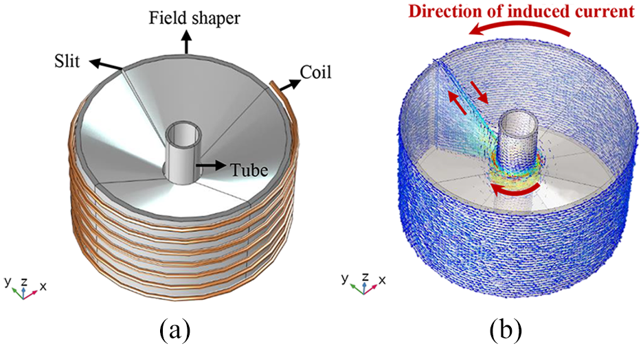
Schematic diagram of the welding device: (a) tube welding model and (b) direction of induced current.
The entire MPW system includes a charging circuit and a discharge circuit, as shown in Figure 2. When the capacitor bank is fully charged, the energy stored in the capacitor bank will be released in the form of a pulse current, and a transient magnetic field will be generated around the coil. The peak current is usually in the range of 10∼1000 kA. Besides, the current in the coil will induce a secondary current on the FS. Due to the existence of a slit in the FS, the induced current flows from the outer wall to the inner wall, as shown in Figure 1(b). In addition, an induced current will also be generated on the metal tube. Compared with the outer wall of the FS, the inner wall has a much smaller area. So, the induced current density of the inner wall is greater than that of the outer wall. Finally, a large repulsive force is generated between the FS and the workpiece.21,22
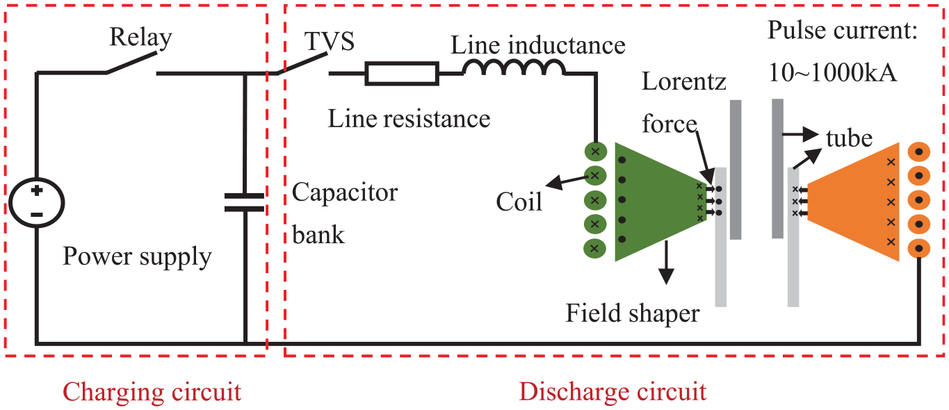
Schematic diagram of the MPW system.
The discharge circuit comprises capacitor bank, coil, FS and tubes. It can be equivalent to an RLC second-order circuit, as shown in Figure 3. Applying Kirchhoff’s voltage law, the differential equation of the circuit with respect to time t is:
Where R is the total resistance of the discharge circuit, including line resistance and coil resistance. L is the total inductance, including line inductance and coil inductance. In addition to the capacitor bank, C also includes the stray capacitance of the circuit. The solution of the differential equation expresses the change of the discharge current with time t, as shown in equation (2).
Where Im represents the discharge current amplitude; U0 represents the capacitor discharge voltage; ω represents the discharge current angular frequency; β represents the discharge current attenuation coefficient.
For the current loop i with radius r, the magnetic flux density at point P (x, y, z) can be obtained by applying Biot-Savart Law. 23 In the cylindrical coordinate system, the mathematical expression of the z-axis direction is:
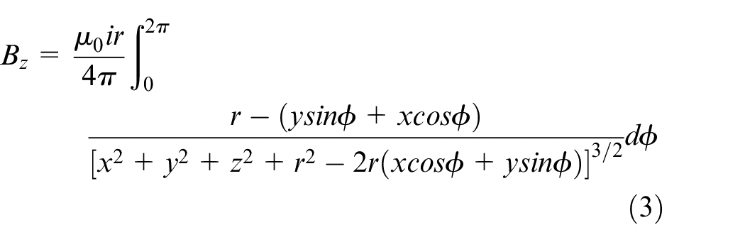
Substituting equation (2) into equation (3) can obtain:
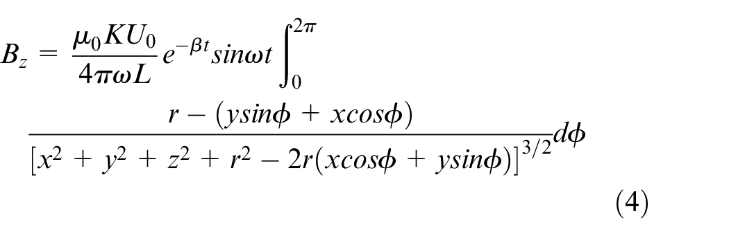
Where K is the shape parameter of the FS.
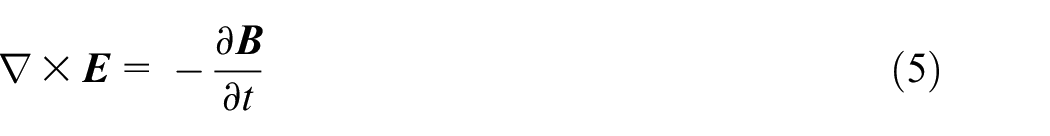
According to Maxwell’s equation, the electromagnetic field can be expressed as:


Where

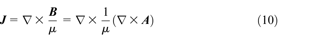
Therefore, the total induced current can be expressed as:
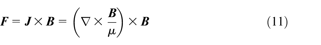
Meanwhile, the Lorentz force on the workpiece is:
Through these equations, the finite element software can be used to solve the electromagnetic field and Lorentz force, and then predict the deformation of the workpiece.
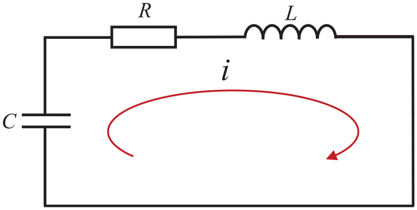
Equivalent circuit diagram of the discharge circuit.
Simulation analysis and design
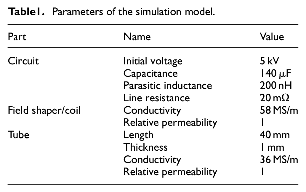
Based on the principle of MPW process, a three-dimensional model was established for electromagnetic field analysis in the COMSOL software. The coil current was calculated through the circuit module and was used as the input of the magnetic field module to obtain the distribution of the magnetic field on the tube. Table 1 shows the parameters of the simulation model. Copper, which has high conductivity and low cost, was selected as the material of the coil and FS. Besides, the spiral coil has seven turns, and the distance between the FS and the tube is 1 mm.
Parameters of the simulation model.
The influence of the cross-sectional shape of the FS
The cross-sectional shape of the conventional FS is shown in Figure 4(a). The length of the inner and outer walls of the FS is determined by the height of the coil and the length of the welding area. The way to change the cross-sectional shape is illustrated in Figure 4(b) to (d). Two triangles were cut off from the cross section. According to the different positions of the cut triangles, three types of FSs are formed, namely T-2 FS, T-10.27 FS, and T-18.35 FS. The coil currents corresponding to these FSs are calculated numerically and compared in Figure 5. It can be seen that the coil currents are almost the same. This means that changing the cross-sectional shape of the FS will not affect the system inductance.
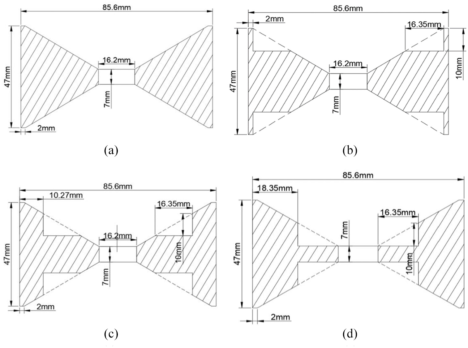
Schematic diagram of FSs with different cross-sectional shapes: (a) conventional FS, (b)T-2 FS, (c) T-10.27 FS, and (d) T-18.35 FS.
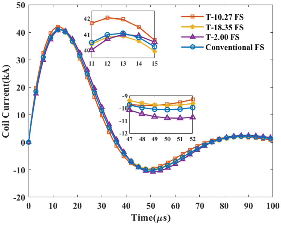
Coil currents under different FSs.
Due to the existence of the slit in the FS, the distribution of the magnetic field on the tube is not uniform. The position far away from the slit has the largest magnetic flux density. Therefore, as shown in Figure 6(a), the magnetic flux density at point P was selected for comparison when using various FSs. According to Figure 6(b), it can be found that the magnetic flux density under T-2.00 FS and T-10.27 FS is very close to that under the conventional FS. However, the maximum magnetic flux density under T-18.35 FS is 13.43 T, which is 1.43 T larger than that under the conventional FS. The main reason is that the structure of the inner edge of T-18.35 FS has been changed, while the inner edge of T-2.00 FS and T-10.27 FS remains unchanged. In addition, the second amplitude is greatly reduced, indicating that the first half of the cycle plays a major role in the tube deformation and welding.
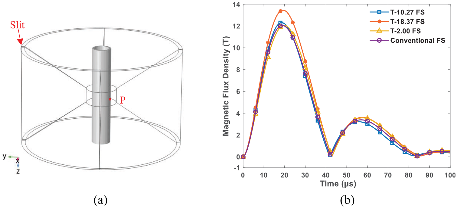
Influence of the cross-sectional shape on the magnetic flux density: (a) the position of point P and (b) magnetic flux density at point P.
The influence of the inner angle of the FS
Since the inner edge of the FS has a direct effect on the tube deformation and welding, the numerical simulation was carried out by changing the inner angle of the FS. The schematic diagram of the inner angle φ is shown in Figure 7(a). The FSs with the inner angles of 0°, 17°, 24.64°, and 31.45° were selected. The cross-sectional area changes with the change of the angle φ, and the minimum cross-sectional area occurs when the inner angle is 0°. Since the conclusion about the coil current is the same as in Section 3.1, only the magnetic flux density at point P was compared and analyzed.
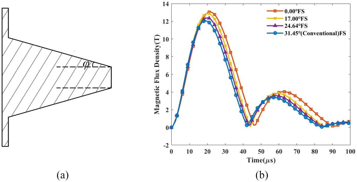
Influence of the inner angle on the magnetic flux density: (a) schematic diagram of the angle φ and (b) magnetic flux density at point P.
Figure 7(b) shows the numerical calculation results. It can be clearly seen that the magnetic flux density is inversely proportional to the inner angle. When the inner angle of the FS is 0°, it has the maximum flux density, and the peak value is 13.05 T. Although reducing the inner angle may improve the deformation and welding effect, the structural strength of the FS will also be reduced due to the reduction of the cross-sectional area. So, it is not conducive to the stable operation of the welding device when the FS is subjected to a large load.
Proposal of concave FS
In order to reduce the loss of structural strength, a concave FS was proposed. The geometric parameters and 3D model of the FS are shown in Figure 8. Two fan-shaped areas, which are tangent to the inner edge, were cut off from the cross-section of the conventional FS. The concave FS can meet both the conditions that the inner angle is 0° and the cross-sectional area is large enough. Figure 9 shows the simulation results of magnetic flux density at point P when using the concave FS. The magnetic flux density reaches its maximum value at 20 μs, which is 13.50 T. This means that the rate of current change is the highest at this time. Besides, the magnetic flux density under the concave FS is increased by 12.5% compared with that under the conventional FS. It indicates that the optimized FS can increase the magnetic field on the tube.
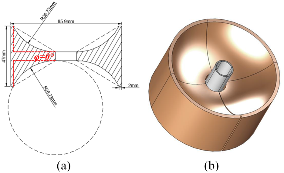
Schematic diagram of the concave FS: (a) cross-sectional shape and size and (b) 3D-model.
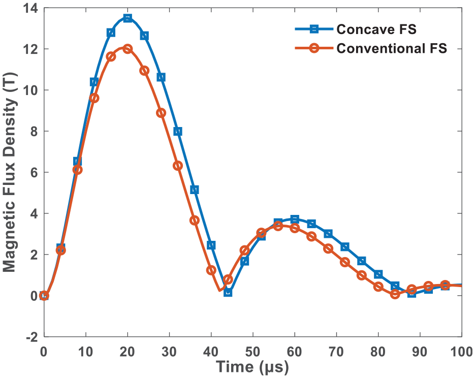
Magnetic flux density under the concave FS.
Structural strength analysis of FSs
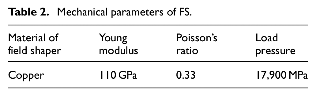
Based on the proposed concave FS, ABAQUS was used to compare the structural strength of conventional, concave, and vertical FSs. The inner angle of the vertical FS is 0°. The FSs have the same mechanical parameters, as shown in Table 2. In addition, a uniform load was applied along the radial direction on the inner wall, and the load value is 17,900 MPa. Figure 10 shows the deformation of the FSs under the large load. It can be seen that the structural strength of the FS is weakened mainly due to the existence of the slit. The slit deformation displacements of conventional, concave and vertical FSs are 2.0318, 3.0085, and 6.42717 mm respectively. It is revealed that the vertical FS has the weakest structural strength since the deformation of its slit is the greatest. For the concave FS, the slit deformation displacement is only 0.97 mm larger than that of the conventional FS. Therefore, the structural strength of the concave FS is close to that of the conventional FS.
Mechanical parameters of FS.
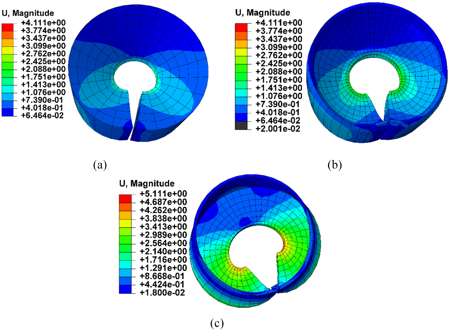
Deformation degree of FSs under large load: (a) conventional FS, (b) concave FS, and (c) vertical FS.
Experiment procedure
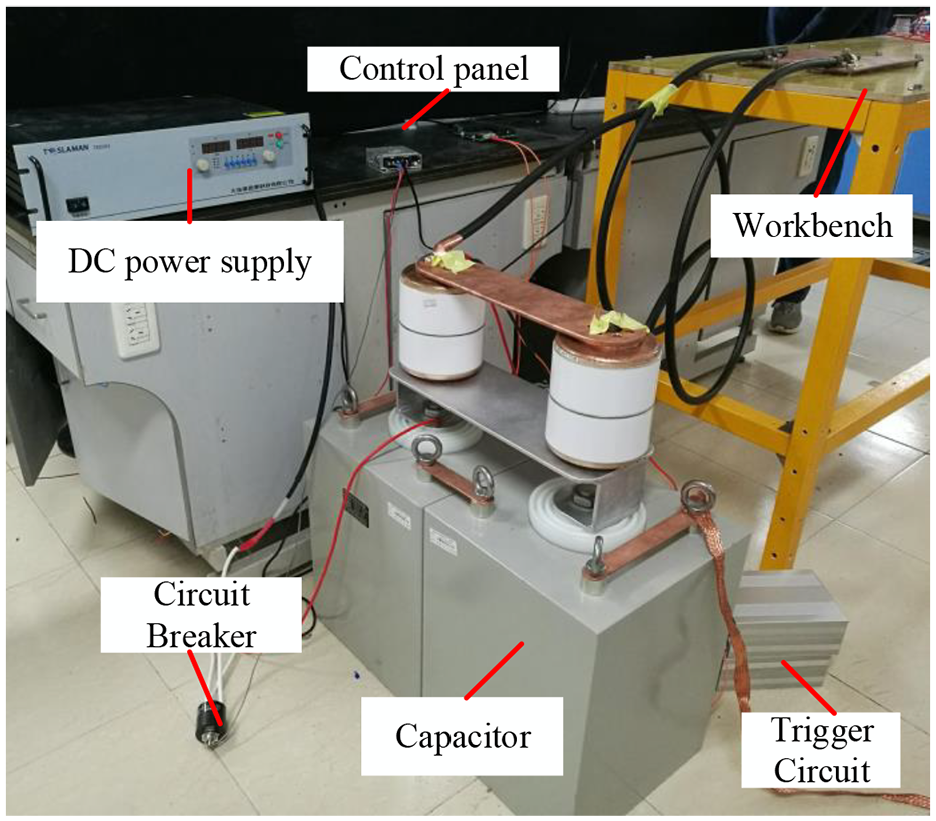
The experimental platform of MPW is shown in Figure 11, including a high-voltage DC power supply with a maximum output voltage of 20 kV, two 70 μF pulse capacitors with a maximum charging voltage of 20 kV, a trigger source with a peak voltage of 5 kV and two triggered vacuum switches. The working parameters of the main equipment are shown in Table 3. In addition, the FS, coil and tube were placed and installed on the workbench in the order shown in Figure 1(a). Figure 12 shows the concave and conventional FSs, which were made of copper. The geometric parameters of the conventional and concave FSs are given in Figures 4(a) and 8(a) respectively. A 6060 series aluminum tubes with outer diameters of 14 and 16 mm were used for deformation experiments. The circuit parameters of MPW are shown in Table 1.
MPW experiment platform.
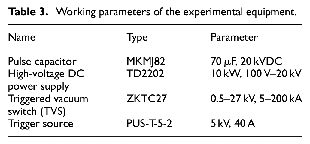
Working parameters of the experimental equipment.
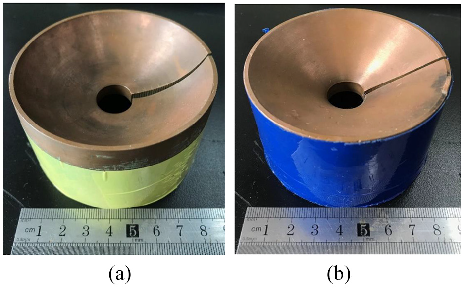
FSs for experiments: (a) concave FS and (b) conventional FS.
The MPW experiment is mainly divided into the following steps: First, charge the pulse capacitors with the high-voltage DC power supply. After the capacitors are fully charged, a circuit breaker is used to disconnect the charging circuit. Then, press the button on the control panel. Instantly, a 5 μs pulse signal will be generated to activate the trigger source to turn on the TVS. Finally, a discharge rod is needed to release the residual voltage on the capacitors. In order to measure the discharge current of the system, it is necessary to place a Rogowski coil on the high-voltage cable and connect it to the oscilloscope before the experiment.
Results and discussion
Discharge current
Figure 13 shows the actual measured discharge current waveforms, which are the attenuated oscillation waveforms. This means that the MPW system was operating in an underdamped state. It indicates that the resistance of the discharge circuit is small and the inductance of the coil is relatively large. Figure 13(a) shows the discharge current when using the conventional FS. The peak value of the current is 40 kA, and the time to reach the peak value is 22 μs. This proves that the effective time of MPW is only tens of microseconds. As the current decays, the current has no effect on the tube deformation. Figure 13(b) shows the discharge current waveform under the action of concave FS, which is almost identical to that in Figure 13(a). It is implied that the system inductance has no obvious change, and changing the structure of the FS will not affect the change rate of the discharge current.
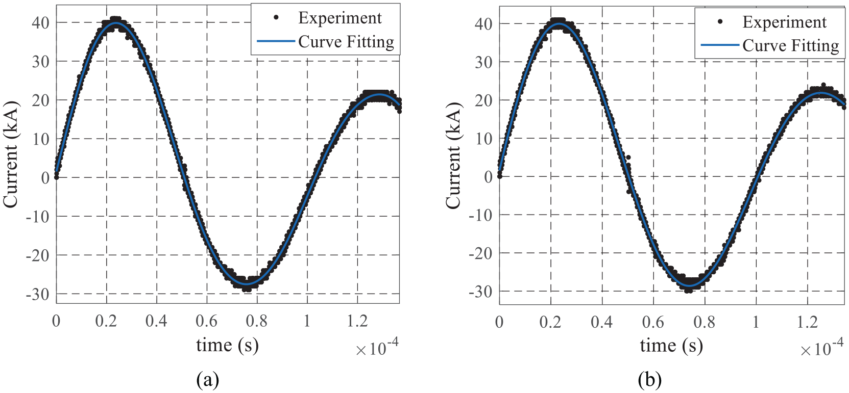
Discharge currents under different FSs: (a) conventional FS and (b) concave FS.
The effect of the concave FS
According to equation (11), increasing the magnetic flux density can improve the electromagnetic force and thus increase the initial deformation velocity of the tube. The velocity determines the deformation and welding quality of the workpiece. Since the entire discharge process is very short, the deformation displacement of the tube under 5 kV is used as a reference in order to verify the magnetic collection capacity of the concave FS. Figure 14 shows the deformation effect of tubes under different FSs. By comparing the deformation results of 14 mm diameter tubes, it can be concluded that the deformation displacement of No. 2 tube is 1.08 mm, which is twice the length of No. 1 tube. For the 16 mm diameter aluminum tubes, the deformation displacement of No. 4 tube is 4.03 mm, which is 77.53% larger than that of No. 3 tube. Therefore, the conclusion that the magnetic collecting capacity of the concave FS is better than that of the conventional FS can be proved. It has been confirmed in Section 5.1 that the discharge current has no difference under the two types of FSs. Therefore, it can be deduced that the concave FS has a larger shape parameter K according to equation (4). Also, it can be further found from Figure 14 that tubes with outer diameter of 16 mm deformed more obviously. This means that shortening the distance between the tube and the FS can increase the electromagnetic force in the desired area.
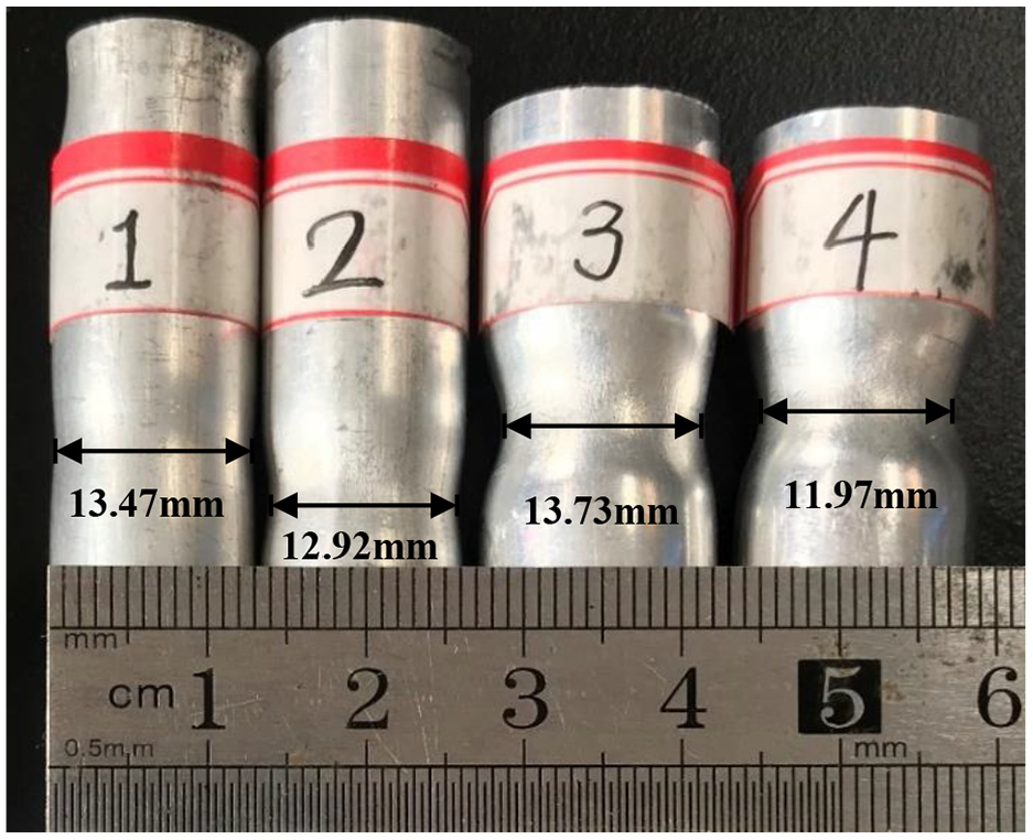
The effect of different FSs (the deformation of No. 1 and No. 3 tubes is under the conventional FS. The deformation of No. 2 and No. 4 tubes is under the concave FS).
The deformation degree of FSs
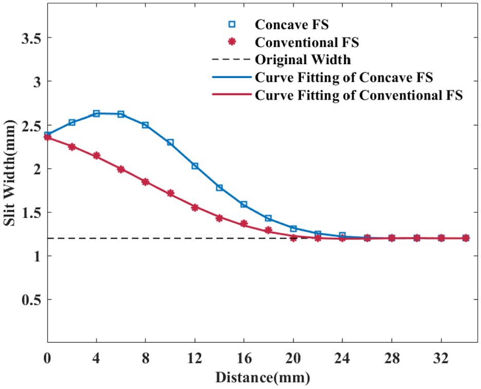
It can be seen from Figure 12 that the slit of the concave FS is slightly wider than that of the conventional FS after the experiment. In order to analyze the deformation degree of the FS in detail, the slit width was measured from the inner edge to the outer edge and the measured data were fitted, as shown in Figure 15. The original slit width of the concave FS and the conventional FS is 1.2 mm. For the concave FS, it can be found that the maximum deformation displacement of the slit is 1.43 mm, which is only 0.27 mm larger than that of the conventional FS. Besides, the maximum deformation did not appear on the inner edge. So, it can be inferred that the induced current density on the surface of the slit is relatively larger in the interval of 4–8 mm. Part of the induced current flows directly from this region to the upper and lower surfaces of the FS. Eventually, a large repulsive force is generated in this area instead of on the inner edge. The maximum deformation position of the concave FS has no significantly influence on the magnetic field distribution. In addition, the deformation degree of other regions is close to that of the conventional FS. Thus, it can be proved that the FS with concave structure does not weaken its strength too much when the magnetic collecting ability of the concave FS has been improved.
Deformation degree of the slit under 5 kV discharge voltage.
Conclusion
This paper studied the influence of the cross-sectional shape and inner angle of the FS on the magnetic flux density, and proposed a concave FS. Both simulation and experimental results have verified the magnetic collecting ability and structural strength of the concave FS. Conclusions can be drawn as follows:
(1) The inner edge structure of the FS directly affects the magnetic field on the workpiece. When the inner angle of the FS is φ=0°, the magnetic flux density on the tube is the largest, which is 13.05 T.
(2) Compared with conventional and vertical FSs, the magnetic flux density has increased by 12.5% and 3.4% respectively when using the concave FS. The structural strength of the concave FS is obviously better than that of the vertical FS.
(3) Changing the structure of the FS has no influence on the system inductance. The shape parameter K of the concave FS is larger than that of the conventional FS, so the concave FS has better magnetic collecting ability.
(4) For the concave FS, the maximum deformation displacement of the slit is 1.43 mm, while that of the conventional FS is 1.16 mm. The concave FS can guarantee the stability of the MPW system.
Footnotes
Declaration of conflicting interests
The author(s) declared no potential conflicts of interest with respect to the research, authorship, and/or publication of this article.
Funding
The author(s) disclosed receipt of the following financial support for the research, authorship, and/or publication of this article: This work was supported by the National Natural Science Foundation of China under Grant 51577016 and Grant 51877014.