
Abstract
Adaptive smart machining has tremendous potential to render machining processes some level of intelligence and smartness. This article presents the concept and innovative use of adaptive smart machining through the adaptive control by constraints system, based on feed rate adjustment to modify the orthogonal cutting force, measured by a smart cutting tool developed by the authors. The advantage of using a smart cutting tool encompasses not only low cost, light weight and compact size, but also within the desired force range it will enhance the cutting tool life and smart machining and hence improve productivity and reliability in adaptive machining applications.
Introduction
The use of computer numerical control (CNC) machine tools has rapidly expanded over the last two decades or so. The advantage of CNC technology is that it reduces the skill requirements for machine operators. Moreover, cutting parameters of the CNC systems, such as spindle speed and feed rate, have been prescribed by a part programmer based on his or her experience or from a fixed machine database in order to protect or enhance the tool usage.1,2 It is well known that tool breakage could increase not only total machining costs but also the total machining time. On the other hand, “tool overprotection” has caused that the CNC machines have been operated under inefficient operating conditions. Due to these limitations of the conventional CNC system and machining algorithms, adaptive machining through adaptive control by constraint (ACC) has been developed to maintain the main cutting force constant in order to avoid tool breakage and maintain high productivity. 3 Generally, however, ACC involves only monitoring one cutting parameter, such as a cutting force, which is maintained around a desired range. Furthermore, using a conventional dynamometer to measure the cutting force for ACC is still difficult, costly and not industrially feasible as there are some limitations in their use, such as the reliability of the sensors in the harsh machining environment. 4 A recent innovation has seen cutting tools with integrated thin film sensor designed to detect wear. 5 In addition, cutting tools are being developed with internal cooling micro-channels or structures to reduce temperature at the cutting tool tip through internal cooling configuration. 6 This trend for additional smart features within cutting inserts or shanks has led to the development of a smart cutting tool embedded with a single-layer piezoelectric film to measure the orthogonal cutting force. 7 The smart cutting tool developed by the authors provides data on cutting force measurement, with a plug-and-produce feature, rendering a simple and compact low-cost sensing tool configuration. The development of adaptive smart machining based on using smart cutting tools and the associated smart algorithms/models has the following potential advantages:
minimization of the machining time;
improvement of surface roughness;
maximization of tool life;
machining on specially geometrized workpieces with high precision and efficiency, such as slender shafts and thin-wall hollow cylinders;
self-monitoring and process optimization;
self-learning and performance improvement over time;
smartness and intelligence required on machining technology;
transparent in the machining through awareness of the cutting process in dynamic real time, such as shear angle, chip formation, cutting forces and interaction within the cutting zone; and
plug-and-produce feature required for both the process and the machining system.
This article presents the concept and innovative use of adaptive smart machining based on the smart cutting tool and process algorithms. 8 In particular, using ACC to maintain the cutting force constant with various depths of cut by adapting the feed rate to (a) protect and enhance the tool when the measured force is greater than the reference force, (b) maintain high productivity when the measured force is less than the reference force and (c) test reliability of the proposed smart cutting tool in adaptive machining applications.
Adaptive control on feed rate using the smart cutting tool for force measurement
The smart cutting tool proposed comprises a cutting insert, a single-layer piezoelectric film, a metal shim and two pieces of insulation tape, as shown in Figure 1(a1). A piezoelectric film PIC181, purchased from PI, functioning as a piezoelectric sensor, has dimensions of 3 × 3 × 0.26 mm and is placed on the top surface of the metal shim. The two pieces of insulation tape are placed on the top of the piezoelectric sensor and the bottom of the metal shim in order to insulate and fix the piezoelectric sensor into position. A wire is soldered onto the metal shim that functions as the output electrode for the piezoelectric sensor. The sensing unit is placed at a distance of 6 mm from the cutting tip between the cutting insert and spacer as shown in Figure 1(a2) and 1(a3). Although the wire and part of the metal shim are exposed from the surface of the cutting insert, it is still some distance away from the cutting tip, as shown in Figure 1(a2). It is necessary to put another piece of piezoelectric film at the back of the insert in order to level the insert up as shown in Figure 1(a3). The smart cutting tool has been calibrated using a Kistler dynamometer, showing close agreement between the measured signals during cutting force measurement; moreover, the cross-sensitivity has been detected to be only 5.97%, determined using a calibrated hammer testing technique. 9 The smart cutting tool has been used to measure the cutting forces by varying the feed rate at three levels of constant surface speed.
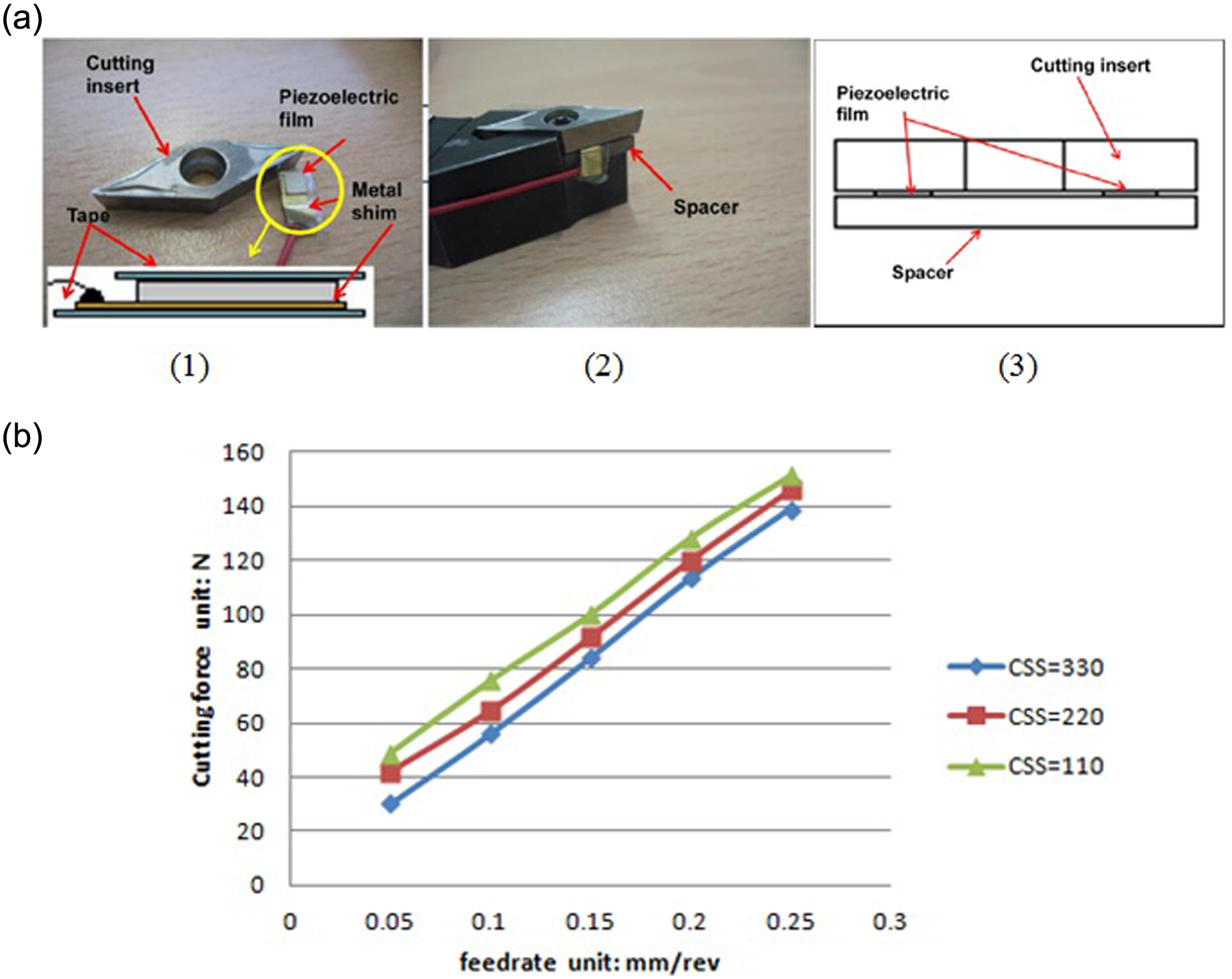
(a) (1) Components of smart cutting tool; (2) integral configuration of smart cutting tool; (3) cross-section drawing. (b) Relationship between feed rate and cutting force in terms of three levels of constant surface speed 110, 220 and 330 m/min.
From the results shown in Figure 1(b), either by decreasing the feed rate or by increasing the constant surface speed, it is possible to reduce the main cutting force. However, it can be observed that adjusting the feed rate has a more significant influence on the cutting force. For example, the cutting force increases by 110 N when adjusting the feed rate from 0.05 to 0.25 mm/rev. In order to keep the cutting force within the desired force range and to maintain high productivity, the adaptive control system has been designed to adjust the feed rate.
A block diagram of a CNC machine with adaptive control is shown in Figure 2(a), where the adaptive control process is based on the smart tool for measuring cutting force and includes a communication interface for extracting current cutting parameters. In addition, using LabVIEW, the user interface program can perform with self-monitoring and optimizing their operations to judge whether the current cutting parameters are acceptable and then provides these acceptable cutting parameters to operate the lathe as necessary. Figure 2(b) shows the linear relationship between cutting force and feed rate at the constant surface speed of 330 m/min and a depth of cut of 0.5 mm; moreover, the equation describing this linear relationship using curve fitting technique is provided. So if the cutting parameters require a depth of cut of 0.5 mm, a feed rate of 0.15 mm/rev with a constant surface speed of 330 m/min, the actual cutting force should be about 84 N, as observed from Figure 2(b), when the cutting tool is of good condition. However, due to the variation in amplitude of the dynamic cutting force signal, the cutting force has been chosen to lie within the control range of 79–91 N. The LabVIEW user interface and cutting trial results based on the adaptive control are described in detail in the following sections.
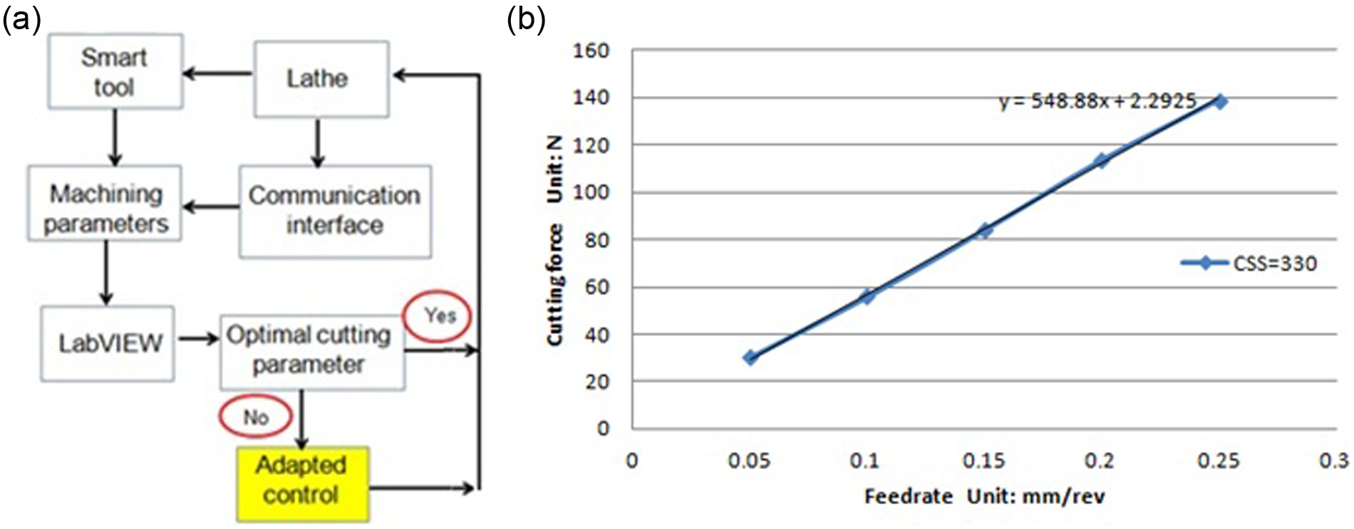
(a) Block diagram of a CNC machine with adaptive control and (b) the relationship between feed rate and cutting force.
LabVIEW user interface for communication and adaptive control
A LabVIEW user interface has been developed, as shown in Figure 3, to extract cutting parameter data, such as feed rate, constant surface speed, depth of cut and spindle speed. The program would also record the main cutting force using the proposed smart cutting tool signals obtained during the machining process. The measured cutting force is then compared with the desired cutting force range in order to adapt the operational feed rate to be an acceptable one, as shown in Figure 2. In order to extract the cutting parameters from a CNC lathe (ALPHA 1350XS), a C++ program was written and integrated into the LabVIEW interface. The function of the C++program is to manage the data transmit/receive sequence, based on the IP addresses with the CNC lathe through Ethernet, and then to obtain the cutting parameters using proprietary coding provided from the Fanuc library.
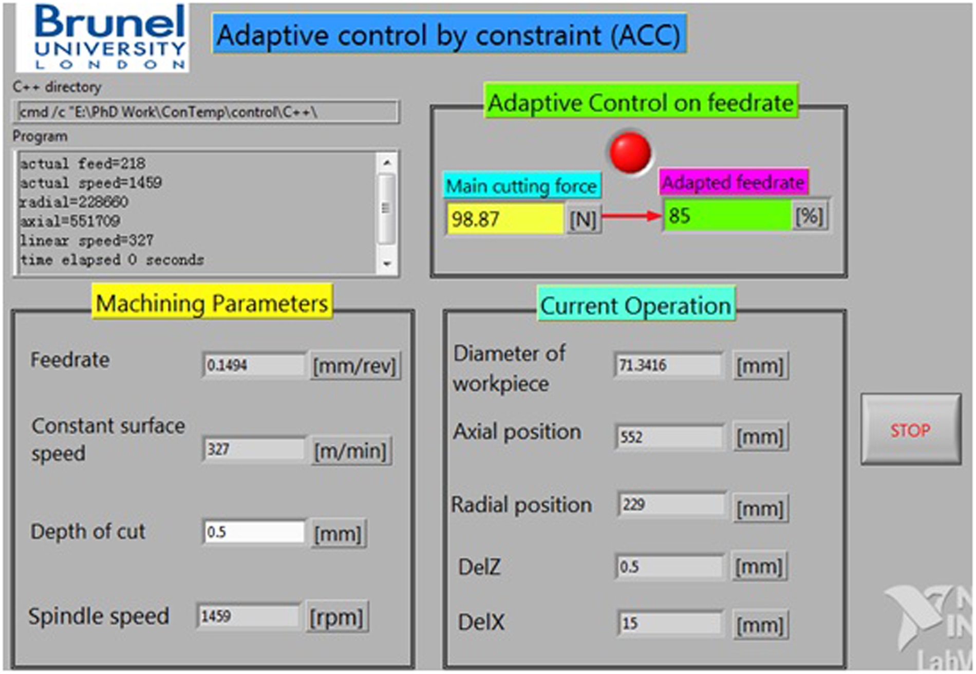
LabVIEW user interface and a screen copy of adaptive control on feed rate.
Results and discussions
The adaptive machining control algorithm, embedded into the LabVIEW user interface, has been implemented in cutting trials with a special designed workpiece as shown in Figure 4(a). The workpiece has been uniquely prepared with shoulders of different height in order to allow different depths of cut to be cut in one cutting pass. For this study, only nine shoulders are used, while the rest of the remaining shoulders will be used in different studies. By keeping the cutting speed constant, the depths of cut of 0.3, 0.5 and 0.7 mm for every three consecutive shoulders can produce three levels of cutting force as shown in the first graph of Figure 4(b).
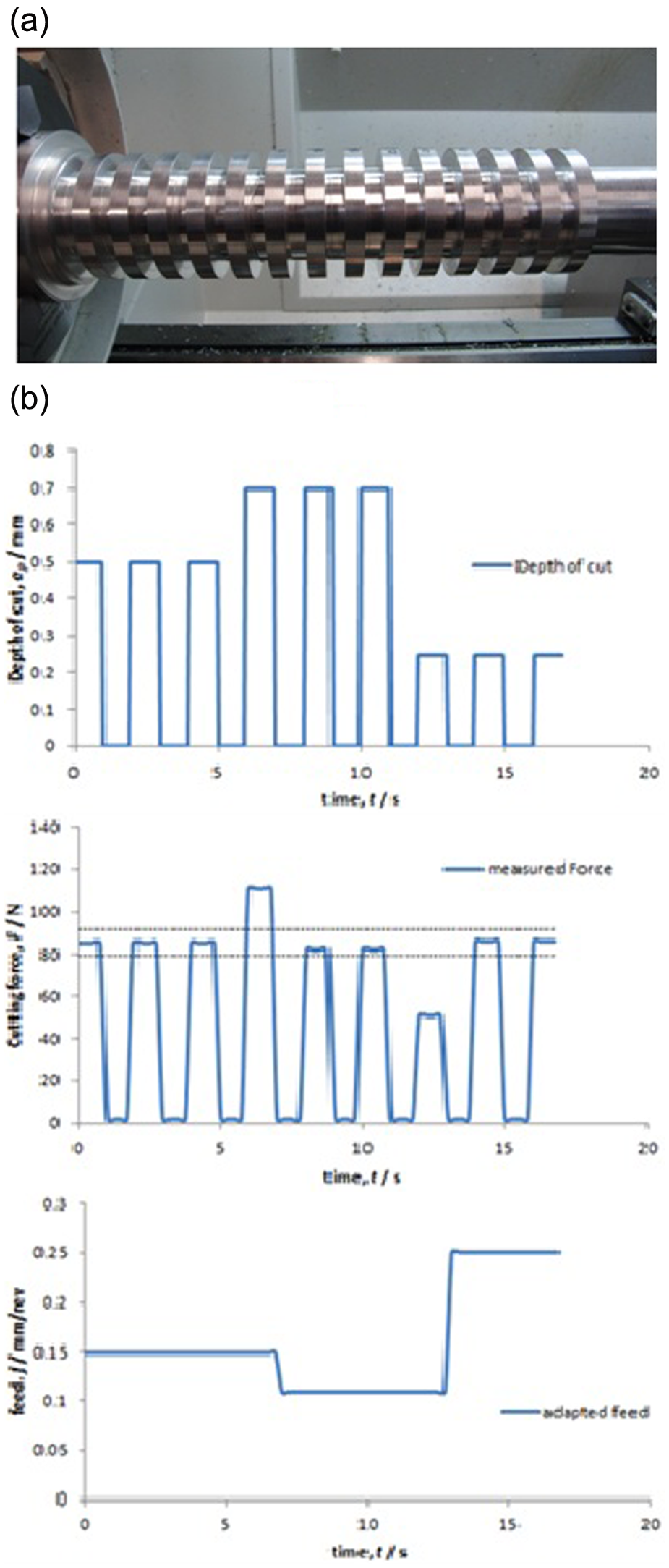
(a) Specially designed workpiece. (b) Adaptation of feed to control cutting force when depth of cut changed.
As recommended by the cutting insert supplier, an uncoated tungsten carbide tool, a cutting speed of 330 m/min, a depth of cut of 0.5 mm and a feed rate of 0.15 mm/min have been defined as the optimum machining parameters for the AL6082 material workpiece. Higher cutting speeds than these can reduce the tool life drastically, thus deteriorating surface quality, while lower cutting speeds might accelerate adhesion wear (built-up edge) and reduce productivity. Therefore, this experiment has been designed to control the cutting force to always be within the optimum region by adapting the dominant cutting parameters (i.e. feed rate in this study) and at the same time to test the reliability of the smart cutting tool with the embedded piezoelectric film.
Three graphs are presented in Figure 4(b). They all have the same time domain in x-axis to show the real-time changes in force signal acquired and the subsequent adapted feed rate parameter when the depth of cut changes. The first shoulders of each depth of cut series are important to determine the optimum feed rate but the feed rate value is only changed (or adapted) at the next gap between the next two shoulders to avoid shock to the tool. The second shoulder of the depth of cut series is meant to validate the adapted feed rate values to be within the optimum region, as confined by the dashed lines in the force–time graph. It can be observed in the second graph of Figure 4(b) that the measured force is greater than the reference force range (between 79 and 91 N), with the unacceptable feed rate parameter during the machining of the fourth shoulder. However, as long as the feed rate is adapted into an acceptable value, the measured force is well controlled within the desired force range during the machining of the fifth, sixth, eighth and ninth shoulder, as shown in the second graph of Figure 4(b). The reliability and reproducibility of the cutting forces acquired by the smart cutting tool are tested at the third, sixth and ninth shoulders.
As depicted in the third graph of Figure 4(b), the communication with the FANUC CNC machine controller can allow the operator to monitor the adapted feed rate online and in real time. In practice, the recommended feed rate value given by the supplier should constantly change when there are changes in machining conditions, such as different physical properties of the workpiece, different wear mechanisms formed on the tool and dynamics of the machine tool. Therefore, real-time communication with the machine tool can improve the adaptive control of the smart cutting tool, using the embedded piezoelectric film and without requiring extra positioning sensors.
Conclusion
This article presents the innovative approach to adaptive smart machining using a smart cutting tool and through providing integrated orthogonal cutting force measurement in the machining processes. Communication between the CNC lathe and the C++ program has been established to extract the relevant cutting parameters. The adaptive control system and CNC machining algorithms are developed based on the feed rate adjustment and embedded into the LabVIEW user interface, so as to achieve constant orthogonal cutting force within the desired optimal force range and thus to maintain high productivity, to extend tool life, to machine specially geometrized workpieces with high precision and efficiency and to optimize machining process variables.
Footnotes
Acknowledgements
The authors would like to thank the UK Technology Strategy Board (TSB) for the useful discussions within the SEEM project consortium.
Funding
This research received funding from the UK Technology Strategy Board (TSB) (SEEM Project, Contract No. BD266E).