
Abstract
This article presents a novel smart turning tool using the embedded piezoelectric sensors for real-time measurement of cutting forces in precision turning operations. The innovation is built with piezoelectric sensor array in the tool shank so as to obtain a smart turning tool, which is robust, industrial feasible and refittable and integrated with adequate measurement accuracy and in-process sensing capability. In the design, four pieces of piezoelectric sensors as an array are integrated into the specially designed tool shank, which directly generate charges under cutting forces. The four charge output signals can be amplified, acquired and processed through decoupling to deduce out the cutting forces with measurement decoupling algorithms. The tool calibration and performance testing are carried out using well-designed cutting trials to further evaluate and validate the tool design in an industrial feasible manner.
Keywords
Introduction
The importance to measure and monitor cutting forces in the machining process real-time has been well recognized by the machining research community and industry. 1 Cutting force measurement in real-time is probably the most direct and effective method to monitor the cutting tool conditions particularly the tool wear and breakage.2–4 In ultra-precision machining of Si-based devices, ophthalmic lenses, or larger optics, it is becoming increasingly important to measure and monitor the cutting forces throughout the lengthy micro-cutting process and correlate the measurement output continuously with the tool and process conditions, and thus render the non-defect surface generation by avoiding any impermissible tool wear occurred in the long-distance turning paths. 5 Therefore, it is essential and much needed to develop a smart turning tool with the reliable and continuous measurement and monitoring capability on cutting forces, which will enable the machining process optimization through real-time cutting force data and smart control of the process parameters6,7 and guarantee the permissible tool wear and tool life for the desired machining distances and cycles.
In the last two decades or so, many types of dynamometer devices with different structures and working principles have been developed for measuring cutting forces and the process monitoring and diagnosing. 8 Exemplars are reported and applied, including the piezoelectric dynamometer,9,10 strain gauge sensor-integrated tool, 11 strain gauge–based octagonal ring-type analogue dynamometer, 12 strain gauge specially structured dynamometer, 13 single-layer piezoelectric film–integrated insert tool14,15 and combined-configuration dynamometer. 16 However, there are limitations for the above-mentioned development, such as their industrial feasibility, high costs of dynamometers, layout constraints (space, weight), the often need for modifying the machine tool structure and the reduction in the system stiffness because of the dynamometer installation as an auxiliary means. 17 Furthermore, the existing cutting force dynamometers or measurement systems have difficulties in reliably measuring the cutting forces in ultra-precision machining processes on shop-floor production environment because of the cutting force scale (normally 0.1–1.0 N scale) and stringent but tedious processes involved.
This article presents the innovative design of a smart turning tool, which employs four piezoelectric sensors as an array embedded in the tool shank for in-process cutting force measurement, supported by built-in decoupling algorithms. The piezoelectric sensor combination is configured in a strain sensor array housed at the head of the tool shank, with four cavity structures accommodating four piezoelectric sensors, respectively. Based on the transverse piezoelectric effect and the structural mechanics, the coupling relationship is established between cutting forces acting at the nose of the turning tool and the output charges of the four sensors. Those four charge output signals are acquired, amplified and then processed with the measurement decoupling algorithms to render cutting force measurement in process. Calibration and evaluation of the smart turning tool are carried out through well-designed cutting trials to further evaluate and validate the design of the smart turning tool.
Design of the smart turning tool
Design of the smart turning tool primarily follows the principles of innovation and industrial feasibility particularly for ultra-precision and micro-cutting requirements, including robust and in-process cutting force measurement, refittable, miniaturization, low cost and matching the dynamometer function, and for future smart machining purpose. The principal technical specifications for a dynamometer are high stiffness, rigidity, measurement accuracy and sensitivity, and refit capability. Therefore, the stiffness and rigidity of the smart turning tool should be designed sufficiently high so as to guarantee its machining operations comparable with conventional turning tools.
In order to meet the tool design specifications, the smart turning tool is designed consisting of an insert polycrystalline diamond (PCD) tool, four pieces of piezoelectric sensors and four protective covers to protect the sensing element, and a specially designed tool shank with four cavities (being symmetric in pairs to provide the four piezoelectric sensors with the high measurement accuracy and sensitivity as required) as shown in Figure 1. The polarization direction of the piezoelectric sensor with the transverse piezoelectric effect (d31 piezoelectric effect) and sensing mode is also pairwise symmetric. The structural characteristics and configuration of the smart turning tool are designed as follows:
A PCD tool insert is placed on the centre of the transverse tool shank.
The cross section of the tool shank is squared and central-axis symmetric with the dimension of 16 mm × 16 mm.
The tool shank cavity section acts as the sensitivity part for stress measurement.
Piezoelectric sensors are mounted in an array and each in about 30 mm away from the tool nose.
Piezoelectric sensors are four pieces of PZT5H in the dimensions of 12 mm × 5 mm × 1 mm and act as the primary sensing elements.
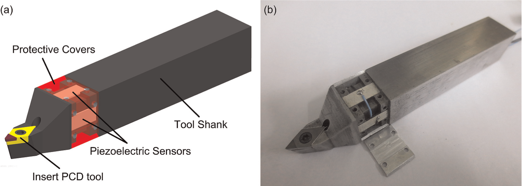
Conceptual design of the smart turning tool: (a) configuration schematic of the smart turning tool and (b) the smart turning tool prototype.
The delicate design configuration and sensing structure of the smart turning tool are appropriately constructed in order to meet the needs of measuring the three cutting force components (Fx, Fy and Fz) accurately through decoupling algorithms, while reducing the tool shank complex stress distribution and overcoming the cross-talk in measurement.
Cutting force decoupling measurement of the smart turning tool
As illustrated in Figure 2, when the cutting forces (Fx, Fy and Fz) act at the tool nose during the machining process, the piezoelectric sensors (P1, P2, P3 and P4) will generate corresponding charges (Q1, Q2, Q3 and Q4) according to the transverse piezoelectric effect. The charges (Q1, Q2, Q3 and Q4) should be amplified through their own respective charge amplifier in order to convert them into the corresponding voltage outputs (V1, V2, V3 and V4) and avoid the charges decay in the process.
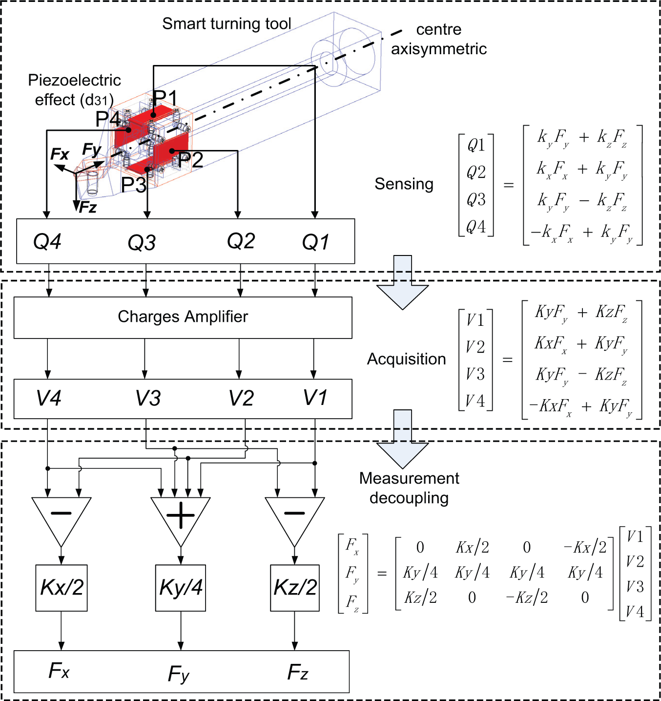
Cutting force sensing and decoupling process within the smart turning tool.
In order to exactly establish the relationship between cutting forces (Fx, Fy and Fz) and four piezoelectric sensors, the four sensor elements are symmetrically arranged to centre axis Y according to the designed tool shank. In the charge distribution analysis of each sensor element, the piezoelectric sensors almost have no charges when subject to the shear stress, and the non-linear effects of the piezoelectric sensors are thus not considered. Therefore, the relationship between the charges and cutting forces can be expressed simply by
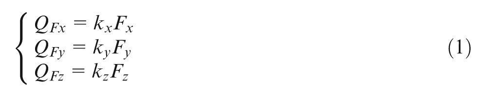
where QFx, QFy and QFz represent the respective charge for each single sensor element under Fx, Fy and Fz, respectively. kx, ky and kz are the corresponding constants to indicate the charge relationship caused by Fx, Fy and Fz, respectively.
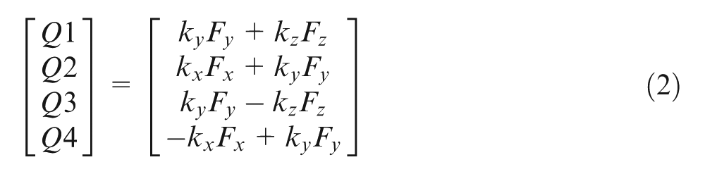
Because of the inserted tool tip placed at the centre of the transverse tool shank, the charges generated by each sensor element are equal under Fy. The charges of the sensors P1 and P3 are opposite electronically, and the charges of the sensors P2 and P4 are 0 under Fx. Similarly applied, the charges of sensors P2 and P4 are opposite electronically and the charges of sensors P1 and P3 are 0 under Fz. In light of the superimposed charge distribution of those four sensors, their charge distribution and charge can be expressed in the following matrix
The relationship between cutting forces and four sensor charges can be decoupled and rendered by the decoupling measurement equation (3) as
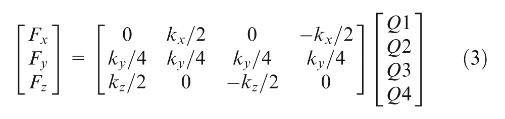
Figure 2 illustrates the total cutting force sensing and decoupling process of the smart turning tool, supported by the underlying decoupling measurement algorithms expressed below
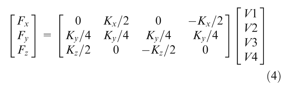
where Kx, Ky and Kz are the constants to express the ratio between the voltage of each sensor after the charges amplify and the cutting forces.
Calibration and testing through cutting trials
Tool sensitivity calibration
As shown in Figure 3, the tool sensitivity calibration is carried out through well-designed cutting trials using the smart turning tool mounted on a Kistler MiniDyn 9256C2. The respective cutting force readings from the smart turning tool and the Kistler dynamometer can be simultaneously compared and thus calibrated accordingly. The material of workpiece is Duralumin 12, and all the cutting trials are performed with the tool under dry cutting conditions. Four charges from piezoelectric sensors are amplified through the charge amplifiers with the highest charge magnification at 40 dB, the output voltage in a range of ±5 V with 50 mV resolution ratio and 100% overload.
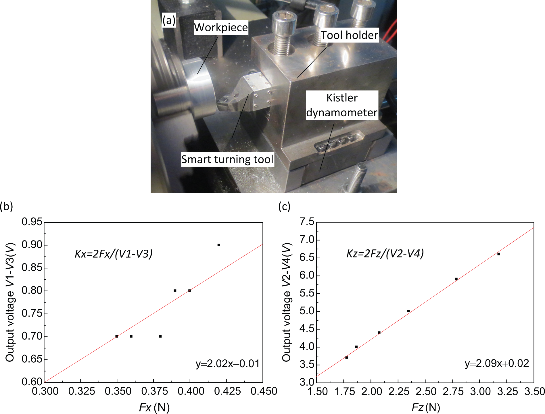
Cutting trial set-up and calibration results: (a) tool sensitivity calibration testing set-up; (b) Kx calibration linear fitting, Kx = 2Fx/(V1 −V3); and (c) Kz calibration linear fitting, Kz = 2Fz/(V2 −V4).
The calibration cutting trials are carried out under the following cutting parameters: spindle speed n = 500 rev/min and depth of cutting ap = 20 µm, with the 2.4-µm linear variation of feed per revolution varying from 2.4 to 14.4 µm/rev. Figures 3(b) and (c) illustrate the calibration testing results; the output voltages and the force signal are recorded from the smart turning tool and the Kistler dynamometer simultaneously. Kx and Kz can be calculated and calibrated from linear fitting. The sensitivities Kx and Kz can be calculated with Kx = 2/2.02 = 0.99 N/V and Kz = 2/2.09 = 0.957 N/V, respectively.
The testing results illustrate the robust relationship between cutting forces (Fx and Fz) and the corresponding sensor output voltages. The cutting force measurement range of the smart turning tool can be calculated with the charge amplifier output voltage in a range of ±5 V, where Fx = ±4.95 N and Fz = ±4.78 N. The thresholds of Fx and Fz can be obtained with the lowest output voltage 0.1 V, where the threshold is almost 0.1 N.
However, as the stiffness of the smart turning tool in Y-direction is much higher than those in X- and Z-directions, the threshold of Fy measured is up to 5 N with a low sensitivity even through the static load test. The output voltage signal of Fy is mixed into 50 mV resolution ratio of the charge amplifier under the calibration cutting experiments. Therefore, the smart turning tool can be used to measure the micro-cutting force in X- and Z-directions at a resolution of 0.1 N but not in Y-direction for Fy, although Fy is often neglected in the cutting process optimization.
Tool testing through cutting trials
To evaluate and validate the performance of the smart turning tool and tool design, further cutting trials are carried out using the same cutting trial set-up as shown in Figure 3. Figure 4 illustrates the cutting force sensing results on Fx and Fz under the following cutting parameters: n = 400 rev/min and depth of cutting ap = 30 µm, with linear variation of feed per revolution from 3 to 13.5 µm/rev.
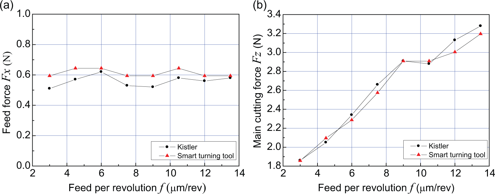
Cutting force measurement results by using the smart turning tool and Kistler MiniDyn 9256C2 in the cutting trials: (a) feed force Fx and (b) main cutting force Fz.
The results demonstrate that the cutting forces measured by the smart turning tool and the Kistler dynamometer (MiniDyn 9256C2) are in good agreement with the acceptable accuracy and sensitivity. The results highlight that the difference is no more than 0.1 N as shown in Figure 4.
Conclusion
This article presents the design of an innovative smart turning tool integrated with a piezoelectric sensor array for cutting force measurement, its implementation perspectives and preliminary application. The conclusions can be drawn as follows:
The smart turning tool is developed for sensing the cutting forces in ultra-precision and micro-cutting, where cutting forces are at 0.1 N scale.
Based on the transverse piezoelectric effect and the sensors’ symmetric arrangement integrated with the delicate design of the tool shank, the relationship between cutting forces and respective electric charges is established and the consequent development is completed particularly on measurement decoupling algorithms for cutting forces.
Calibration testing and cutting trials demonstrate the cutting force sensing approach using the embedded piezoelectric sensor array, and the smart turning tool design is industrial feasible and innovative, supported by the measurement trial data, that is, cutting forces Fx and Fz with a range of ±5 N and the threshold resolution of 0.1 N.
Footnotes
Declaration of conflicting interests
The authors declare that there is no conflict of interest.
Funding
This research received financial support from the National Natural Science Foundation of China (NSFC; grant no. 51205086).