
Abstract
This work deals on a straightforward methodology for analysing and identifying impact fractures in polypropylene commercial pipes through experimental tests and numerical procedures. The pipes are characterized by brittle behaviour at low temperature (0 °C). Laboratory experiments, at different conditions, explain the material behaviour and support the numerical study of the pipes to external blows and the dynamic simulation of the crack growth.
The implemented numeric procedure enables us to follow the fracture path evolution by selectively deactivating the finite elements. Comparisons between impact tests and simulations, fracture toughness and the energy release rate, shows that the proposed method simulates the impact effects accurately and rapidly and allows the damage identification. Furthermore, the onset of clearly visible damage is correctly predicted.
Keywords
Introduction
Current standards drive the industrial producers toward new experimentations of their products against fractures owing to impact occurrences. 1 Pipes made of polypropylene, widely employed for plant applications, 2 are subject to such events during their use but also installation. Traditional approaches based on visual inspection are not able to detect small levels of damage. For this reason, a rapid and precise tool for identifying damages is essential in order to assess the integrity of the products and their operative limits in term of physical variables.
The mechanical behaviour of polymers like polypropylene can be influenced by a number of factors, some deliberately introduced and others related to the external environment. Among these, the following ones can be mentioned: mineral fillers, temperature and humidity of the external environment in operating conditions. Inorganic mineral fillers have been introduced into polymer compounds to reduce the cost and improve the stiffness and dimensional stability. Generally, the addition of inorganic fillers has an embrittling effect on polymers and results in a significant decrease in toughness. 3 The environmental conditions also affect the polymer strength and the mechanical behaviour;4,5 polypropylene can show a particularly brittle response at low temperatures, and the phenomenon decreases as the temperature increases. Furthermore, exposure to wet ambient conditions modifies the brittleness of such materials. High values of relative humidity lead to softening and to a ductile response.
In this study, a wide series of commercial polypropylene pipes are tested in the laboratory under impact loading, at varying fixed temperatures. At 0 °C they show brittle fractures. This article is aimed at reproducing and understanding such brittle responses by means of experimental tests and numerical analysis, providing an effective and simple numerical method, based on available tools. It is revealed to be useful for modelling cracking and further evaluating the modifications to the material compound that can prevent it.6,7
Several works address the issue of fracture simulation under generic quasi-static load conditions by means of finite elements (FEs) re-meshing strategy.8–10 It enables a highly accurate tracing of the crack geometry and evolution, at the same time preserving an adequate element shape. Re-meshing methodology is commonly implemented in commercial multipurpose FE codes, often as an additional tool. Beside, it can be onerous for high computational costs and projection errors associated with conventional FE methods, in particular when high load velocities are expected and three-dimensional (3D) solid FEs implemented.
The extended FE method 11 can partially overcome such complexities allowing it to represent the entire crack independently of the mesh, and so re-meshing is not necessary to model crack growth. This result is achieved at the cost of restricting the discontinuities to the mesh edges, as well as primarily defining the crack path and tip. However, this technique still has to be improved in order to deal with complex configurations such as large deformation crack propagation, multiple cracks, impact loading, etc. 12
The issue of removing springs or finite-elements as a model for fracture is addressed in literature.13,14 It is used also for implementing the virtual crack closure technique (VCCT) to calculate the transient strain energy release rate under impact loading in brittle materials. It is a fascinating strategy for understanding the crack behaviour with the prescribed crack path.
A methodology called crack band model is suggested in Bazănt and Cedolin,15,16 to describe the distribute damage as cracking by a stress–strain relation with strain softening on the macroscale. The basic idea is to prescribe a certain width of the crack band in a FE mesh that represents the material’s characteristics, so that the mesh dimension can be fixed by evaluating macroscopic properties. So, cracks are considered to be densely distributed (smeared) throughout the finite area of the element. Another procedure, that is similar in some respects to the crack band one, is the so-called element vanishing technique, subsequently developed by means of a plane FE mesh for ductile ruptures17,18 and rapid loading conditions. 19
This article presents a simple methodology, freely inspired by the crack band model, of simulating the 3D brittle crack in polypropylene pipes under impact loading at low temperatures. This is achieved in dynamic conditions without a prescribed crack path and without using re-meshing techniques, by means of a subroutine implementation into a commercial multipurpose FE code. The proposed procedure is able to develop a selective element deactivation with removal and can be used when the model is developed in three dimensions, formed by solid elements and when high velocities, such as impact speed, are involved in the analysis. Branching could be also reproduced. 7
The study follows two main phases: preliminary standardized laboratory tests on a universal machine and a striker, 3D FE simulations.
The standardized laboratory experiments aim at identifying polypropylene material characteristics in quasi-static conditions and evaluating the polypropylene pipes impact response through dynamic drop tests on selected specimens.
The laboratory facilities consist in an axial-torsional universal machine and a striker. The first machine is used for the material characterization in quasi-static conditions. The second facility investigates the pipe specimen response under a dynamic impact load. They are equipped with thermal chambers for fixing the specimen temperature; consequently all tests are performed at a constant temperature and room humidity.
The numerical models have been developed into the commercial multipurpose FE code MARC. 20 The approach presented herein for the virtual crack simulation under impact loading is general and can be implemented into multipurpose commercial FE codes that allow the programing of user subroutines and elements deactivation.
Laboratory tests: quasi-static conditions
Quasi-static experimentations are performed to investigate the material behaviour at different temperatures. The resulting stress–strain data are employed in the following section for 3D numerical simulations on pipe structures. Indeed, MARC 20 allows the achievement of 3D FE analyses with solid elements, using the material experimental data collected by means of a uni-axial test on universal machines. It is effectively performed for an isotropic material, like polypropylene, but also when characteristics are different. 21
During the uni-axial experimentations, the actuator is driven in displacement control at a constant rate and temperature is fixed by the thermal chamber. The data collected consist of axial forces, stroke displacements, linear extensometer displacements (on 10 mm of base) and test temperatures. Several specimens are extracted by a punch from polypropylene commercial pipes with a suitable profile. They have a constant thickness, equivalent to the pipes one, with the classic dog-bone shape and they are tested in tension up to rupture. Their geometry consists in a total length of 115 mm, with 25 mm width where the hydraulic grips clutch the specimen. In the central part, where the extensometer is applied, dimensions are 45 × 5.7 mm.
Material characterization
Figure 1 reports a series of stress–strain polypropylene characteristics at different test velocities (6, 50 mm/min) and temperatures (0 °C, 24 °C, 60 °C, 80 °C). The data are collected by the extensometer device and the load cell. The specimens’ compound consists in 50% polypropylene and 50% talc with colour and fire resistant additives.
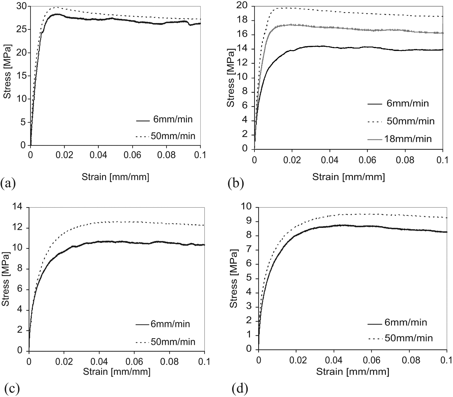
Stress–strain polypropylene characteristics at different test velocities. Data collected by extensometer device and load cell. Test temperature is fixed at constant values: (a) 0 °C, (b) 24 °C, (c) 60 °C, (d) 80 °C.
At a low temperature (0 °C, see Figure 1(a)), minor differences (less than 2 MPa at the stress peak value) are highlighted in the results between the two adopted test velocities (6 and 50 mm/min). When the temperature is fixed at room temperature (24 °C), test rates influence the material behaviour more clearly (Figure 1(b)). For this reason, three test rates have been investigated (6, 18 and 50 mm/min) and about 6 MPa of difference between the peak stresses at 6 and 50 mm/min are recorded. Finally, when the temperature is fixed at high values, around 60 °C–80 °C (Figure 1(c) and (d)) a weaker dependence of the material behaviour on the test rate is reported.
Figure 2(a) highlights the variation of the characteristic curves, and the axial peak stresses of the specimens with temperature. The experimental rate is fixed to 50 mm/min. It is also worth noting, the specimens reach complete rupture with variable total deformation depending with the temperature level. In particular: around 30% of limit elongation at 0 °C; 45% at 24 °C; 150%–200% at the highest ones (Figure 2(a)). The stroke velocities adopted in the tests do not influence the rupture limit. During the tests, some unloading–reloading cycles are also performed to evaluate possible unusual responses.
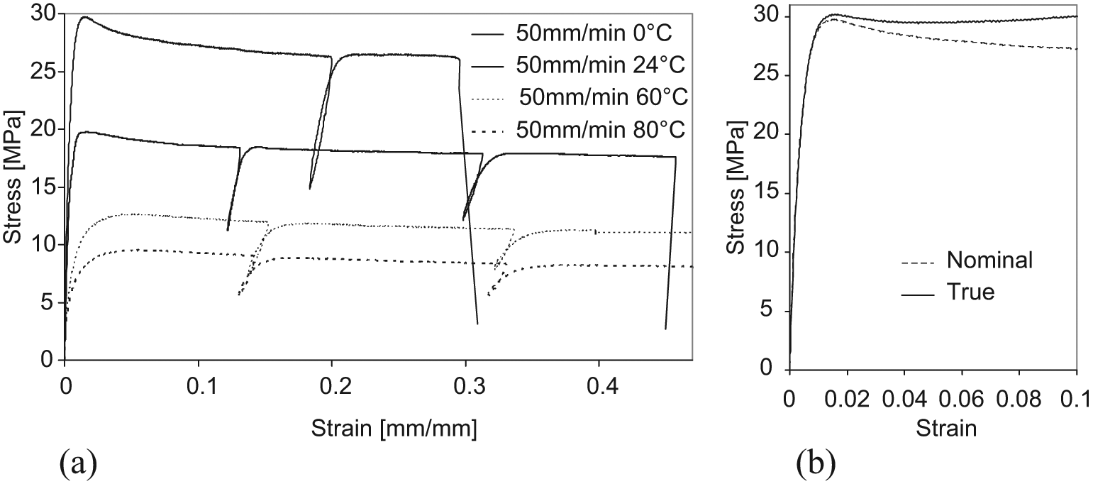
(a) Stress–strain polypropylene characteristics. Data collected by extensometer. Experimental rate fixed at 50 mm/min. (b) True stress and strain curve 0 °C 50 mm/min.
Of course, Figure 2(a) depicts engineering stress and strain. These data are converted into true stress and strain, 22 as shown in Figure 2(b), when temperature is fixed at 0 °C and the experimental rate at 50 mm/min. In such conditions, the 0.5% secant modulus is 4500 MPa, the 1% secant one 2900 MPa and the Poisson ratio 0.4. The mass density results are close to 1300 kg/m3.
Laboratory tests: dynamic conditions
The referenced standard 1 specifies a scheme to investigate the resistance of thermoplastic pipes to external blows by the round-the-clock method. Polypropylene pipe specimens, characterized by a nominal diameter (DN) of 50 mm and 75 mm (with 2 mm and 2.5 mm thick, respectively) and length of 150 mm, have been tested. They are placed under the striker at fixed temperatures (0 °C, 24 °C, 60 °C).
In order to evaluate pipes’ resistance to external blows, the impact mass strikes the external surface of the specimens in specific positions, depending on the external diameter. The shot is characterized by a total mass of 0.5 kg, with a 25 mm diameter, falling down from increasing heights.
During the impact tests the mass fall heights have been measured and the effects on the specimens have been recorded (Table 1). Fractures occur exclusively at the lowest temperature (0 °C) with markedly brittle aspects. In such conditions, for each pipe typology, it is possible to fix, after a visual inspection, the critical limit of impact mass fall height. Namely: (a) 210 mm for DN50 specimens, equivalent to 650 mm/s of impact rate; (b) 290 mm for DN75 ones (760 mm/s impact rate). Under and close to such limits, little extended fractures can occur (Figure 3(a)). Overcoming these levels, the specimens always present complete fractures, with an evident main crack along the whole length of the specimen (Figure 3(b)).
Dynamic impact tests: results.
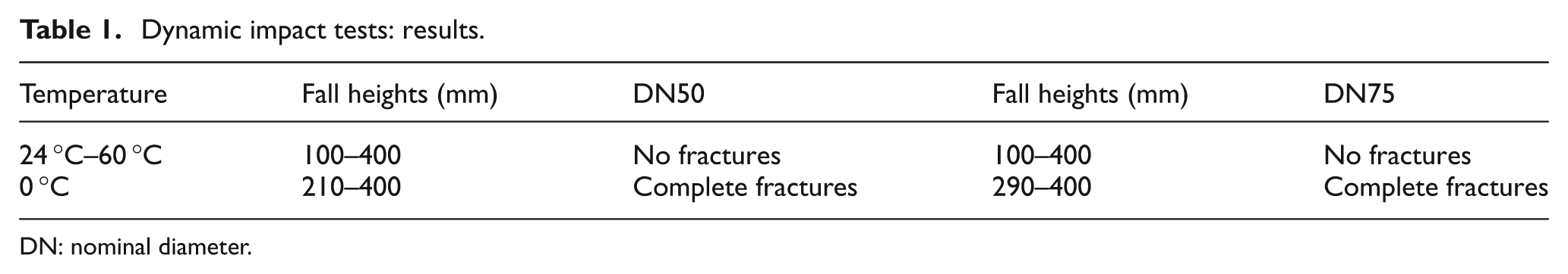
DN: nominal diameter.
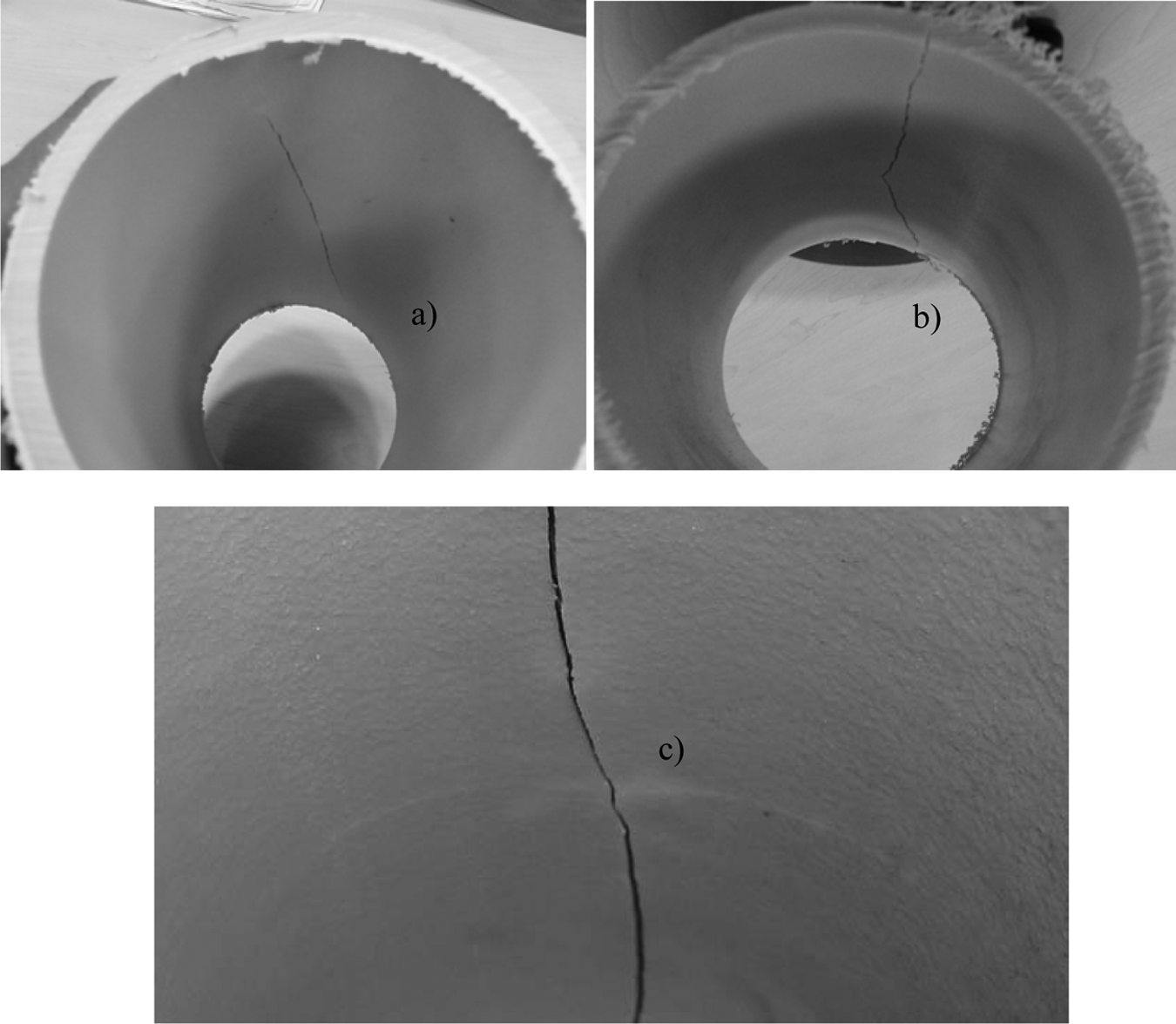
Little extended fracture for fall heights around the critical values (a); complete fracture (b) with whitening details (c).
Figure 3(c) depicts the main fracture detail in the internal pipe surface, close to the impact position, where a slight whitening can also be observed. The main fracture propagation is always parallel to the longitudinal axis of the pipe and it is always characterized by brittle behaviour. At critical impacts the crack extends to the complete thickness, from the internal to the external surface. Branching has not been detected during the dynamic tests on a hundred specimens.
Dynamic analyses on 3D FE models
The physical problem of a body subjected to impact loads is characterized by several nonlinearities that must be captured by the numerical simulations. The multipurpose FE code MARC is used to achieve dynamic analyses of 3D numerical models with pipe specimens during impact drop tests. The direct integration method is used for solving the equations of motion. Large strain and displacements are taken into account with a Lagrangian approach implementing the Newton–Raphson iterative procedure for establishing the dynamic equilibrium. 20 The contacts between the impact mass, the pipe and the base support have been taken into account, in addition with a constant friction factor (0.1).
In this section, numerical simulations of the impact problem will be presented and a number of issues discussed. Such as the:
mesh elements size for the whole structural problem discretization;
virtual crack method with the deactivation of elements;
numerical criterion for selecting the elements to be removed;
mesh element size to be applied in the crack spreading area;
3D impact FE simulations of the brittle fracture in pipe specimens.
Problem discretization
Dynamic tests performed are characterized by an impulsive excitation. From preliminary investigations, a Fourier analysis of the dynamic load input shows that only frequencies below fh = 800 Hz are contained in the loading. Then, following the approach presented in Bathe,
23
the FE mesh should at most represent accurately the frequencies to about the cut off frequency fco = 4fh = 3200 Hz of the actual system. Consequently, the time step

The perturbation transversal wave speed vtw and bulk wave speed vbw can be evaluated by the Lamè shear modulus µ, the bulk k and the mass density ρ as follows


The critical wave length, the FE mesh must represent, is

The time step and the corresponding effective length (equations (1) and (4)) can characterize the main wave travel accurately and they could be chosen differently, depending on the element typology and the time integration scheme. In this article only linear elements are implemented, so the maximum effective length is assumed to be the same herein evaluated. Size element variations will be introduced only in the fracture propagation region owing to the technique for virtual crack simulation. The integration scheme is the Newmark constant-average-acceleration one, which also results in good agreement with the calculated time step. 23
Virtual crack method with elements deactivation
Addressing the virtual crack method with elements deactivation (VCMD), we ought to make some considerations regarding the crack formation. A fracture energy value on the crack surface is required. In other words, the basic concept is an energy balance between the strain energy in the structure and the work needed to create a new crack. This energy balance can be expressed using the energy release rate G: the crack propagation occurs when G is equal to a critical value Gc, or fracture toughness of the material. This property is determined from laboratory experiments and, considering commercial plastic compounds, it is usually declared by the producer.
The energy release rate is defined as G = –∂U/∂a, where U is the potential energy of the system, function of the crack length a in the direction of its propagation, the energy dissipated during fracture per unit of newly created fracture surface length. By definition, G is independent on the crack width.15,16 Within a FE mesh, the potential energy release rate at crack extension can be approximated as

where Δa, growth of the crack length, is given by the typical size of FE.
The energy release rate concerns the stability of the fracture propagation, the growth speed and the conditions that allow the arrest of the crack. In the development of the VCMD, the dependence between the energy release rates, the element size and the convergence of the numerical analyses stem from the tests performed.
Generally, it is possible to calculate the total energy release rate Gtot as15,16

The three contributions GI, GII, GIII, with respect to the three basic fracture modes (I-opening, II-in plane shear, III-anti plane shear) can be evaluated for linear elements as
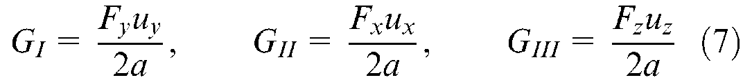
where x, y and z are the coordinate directions in the local crack tip system, more or less parallel to the global system, Fx,y,z the nodal forces along the three directions x, y, z before the crack opening and the elements deactivation, ux,y,z the relative nodal displacement after the crack opening and the elements deactivation. Figure 4 presents schematically the formulation of the VCMD on a plane mesh in the case of fracture mode I.
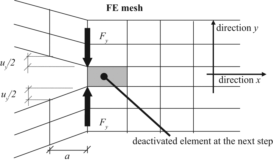
Formulation scheme of the VCMD.
The dynamic approach applied in this study for the impact analyses, characterized by brittle fractures at a low temperature, assumes that the system does not show damping.
The deactivation scheme, operating between the preceding and the succeeding time steps, changes the expression of the tangent stiffness and the mass matrices, respectively, indicated as
the solution of the nth time step where the Newmark method and the Newton–Raphson procedure are applied;
the deactivation procedure between the end of the nth time step and the beginning of next n+1th time step.
The total numbers of degrees of freedom of the system consist in the node number kn with three degrees of freedom for each node, so the


where
Criterion for element deactivation
Following the Galileo–Rankine–Navier (GRN) criterion, 24 the limit states of cracking for a brittle material can be estimated as its elastic limits, in tension and in compression. They are evaluated by a uni-axial test. So, in order to avoid fractures in the system, the following relation has to be satisfied

where σ c and σ t are the stress compression and tension elastic limits and Sa is the principal stresses (with a = I,II,III; where I subscript stays for maximum – tension, III for minimum – compression).
The GRN criterion is used here in a modified version for implementing the element deactivation in the VCMD. It has been considered only for the SI maximum principal stress, believed responsible of the crack opening. Then, a linear elastic, isotropic and tension–compression non-symmetric material model is used for the impact simulations.
The cracking criterion based on the experimental value of tensile strength can lead to a loss of objectivity in the FE numerical analysis. To overcome this problem, an approach based on fracture mechanics concepts15,16 has been adopted in this work within the FE mesh for dynamic analyses.
From

where c is a numeric constant that depends on the type of FE (0.826 can be assumed for solid elements), w is the size of FE in the mesh (0.0025 m is herein adopted as the significant value). The constant
A numerical procedure has been implemented in the FE environment to simulate cracking by means of the VCMD. It consists in a MARC user-subroutine programmed in Fortran, which allows us to follow the fracture path, spreading in time and space. So, at the end of each time step of the system-direct integration, the numerical procedure (a) checks if the tension stress limit, defined by the user, is overcome by the principal maximum stress calculated at the elements Gauss points, (b) deactivates the elements where the condition of the previous item is verified, (c) updates the state of the system for the beginning of the next time step. No crack path or restriction for the elements deactivation is designed a priori. The virtual crack spreads in three dimensions, step by step. It can be influenced by the fracture criterion and the mesh element size.
The methodology of implementing special procedures by a user subroutine in commercial codes is very general and allows us to simulate numerically structural performance and techniques in powerful multipurpose work frames. 27
Preliminary assessments of critical impacts
This section evaluates the impact of the size of the elements involved in the VCMD. The mesh refinement is taken into particular consideration in the specific area where the crack spreads. In the remaining part of the mesh, the element sizing is considered in the same terms as that evaluated by the general wave propagation theory (‘Problem discretization’).
The DN75 and DN50 pipe specimens are preliminarily modelled in a plane strain configuration (type 11 MARC four-node, isoparametric elements 20 ) so as to overcome computational complexities in the evaluating of the numerical efficiency of the VCMD, without losing details on the material constitutive law and general analysis conditions.
The models consider the transversal section of the pipes with the material constitutive characteristics discussed in the previous sections, with the aim of observing brittle responses, as shown during the dynamic experimentations at critical impacts and 0 °C fixed temperature. The boundary conditions reproduce standard tests. 1 The impact body has an equivalent linear mass (3.3 kg/m). The maximum element size along the pipe circumference is fixed to the value in equation (4). From this preliminary arrangement, a number of models are prepared increasing the element refinement at the impact location.
Table 2 reports the results of the performed numerical analyses. Several aspects have been checked, namely: the volume of the deactivated elements at the end of the fracture simulation with the corresponding deleted kinetic energy; the related minimum circumference element size; the variation of the impact body kinetic energy at the same height (before and after the impact); the energy release rate evaluation (by energy balance); the numerical convergence of the nonlinear dynamic analysis. The resulting observations can be summarized as follows.
Preliminary analyses on plane strain FE models.
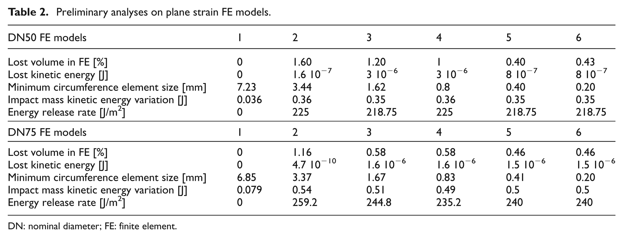
DN: nominal diameter; FE: finite element.
For both DN50 and DN75 specimens, the removed volume decreases until a certain minimum circumference element size level. From that point, it remains almost constant. No. 1 models do not show crack opening.
For the No. 2–3 DN50 and No. 2 DN75 models, the removed element volume is larger than 1% of the total initial volume (limit value herein adopted for verifying mass conservation during the analysis). However, lost kinetic energy results are negligible.
The impact mass kinetic energy variation over No. 2–6 models stays more or less constant. Its results are dissipated by the crack opening, with a small part transferred to the pipe post-impact vibrations (estimated close to 15% by transient analyses on fractured arrangements). The material constitutive law and the adopted small friction coefficients exclude different dissipation sources.
No. 1 DN50 and DN75 models show a very slight reduction of the kinetic energy variation because the crack has not been opened and it is entirely transferred to the pipe post-impact vibrations.
The energy release rate for No. 2–6 models is in good agreement with fracture criterion assumptions in ‘Criterion for element deactivation’. Convergence is verified on all models.
Figure 5 depicts the detail of the opened crack around the impact position at the end of the analyses: namely Figure 5(a)–(f) for the No. 1–6 DN50 FE models and Figure 5(g)–(l) for the No. 1–6 DN75 FE ones. For both specimen diameters, the highest element refinement does not seem to be useful and the main crack shape is determined from model No. 5.

Elements deactivation at the end of analysis. FE models No. 1–6: DN50 (a)–(f), DN75 No. 1–6 (g)–(l). See also Table 1.
To investigate the influence of the mesh refinement, two modified No. 5 models are developed (Figure 6(a) and (b) with reference to Figure 5(e) and (k), respectively). The resulting shapes result equivalent.
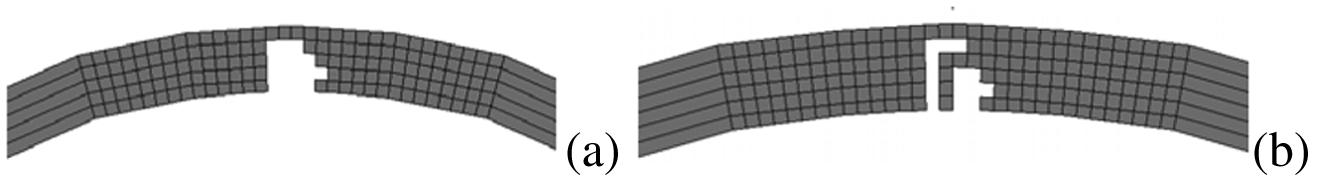
FE models No. 5, extension of the refined area: DN50 (a), DN75 (b).
3D solid models
From the plane strain preliminary analyses, FE models No. 5 result in a good compromise between crack simulation and computational efforts. In light of these observations, 3D solid models of the DN50 and DN75 pipe specimens have been implemented and tested for reproducing the brittle response detected during the laboratory dynamic tests at critical impacts and 0 °C fixed temperature. They have been developed considering a half pipe for symmetry and meshed by MARC type 7 3D, eight-node, first-order, isoparametric elements. 20 The linear elastic, isotropic and tension–compression non-symmetric material model has been used, as in the plane strain analyses.
Critical fall heights are correctly predicted and the fracture characteristics match those observed on the specimens in the dynamic conditions. Moreover, the energy release rate is evaluated close to the fracture toughness at 0 °C (‘Criterion for element deactivation’). For the sake of conciseness, in the rest of this section, only the DN75 specimen will be accounted. However, the observations can be extended to DN50 configuration.
The implemented mesh in the transversal and longitudinal direction is depicted in Figure 7. Boundary conditions consist in the symmetry ones (xy plane) and the standard support at the specimen base (Figure 7(a)), herein simulated with rigid body characteristics. 1 The impact mass is also modelled as an equivalent rigid body, with vertical translation exclusively allowed. The dynamic equilibrium is calculated on the deformed configuration.
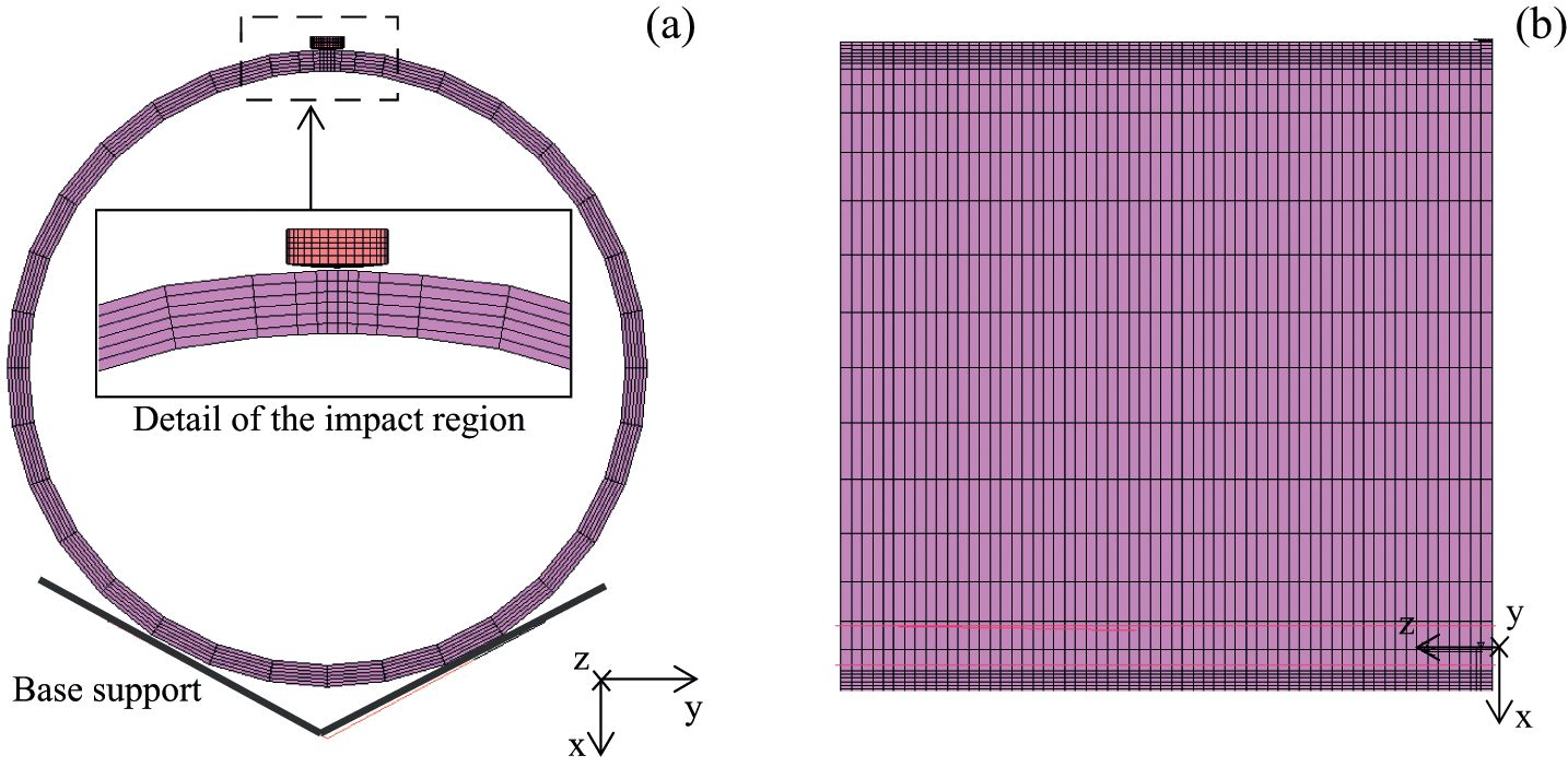
DN75 FE mesh in transversal (a) and longitudinal direction (b).
Figure 8(a)–(e) depicts the contour bands of the vertical displacements on the top view of the DN75 specimen at different time instants. The crack propagation follows the expected direction along the longitudinal specimen axis (z). It is worth underlining that the vertical displacements, during the fracture spreading, remain symmetric with respect to the propagation direction (Figure 8(a)–(d). However, when the crack is complete, a separate vibration between the two specimen edges can be recognized (Figure 8(e)). Figure 8(f) is devoted to show the longitudinal section of the DN75 specimen at same Figure 8(d) time instant (crack completion): slight scattering in the deactivated FE can be observed adjoining the impact region, while distantly the fracture surface appears more flat.
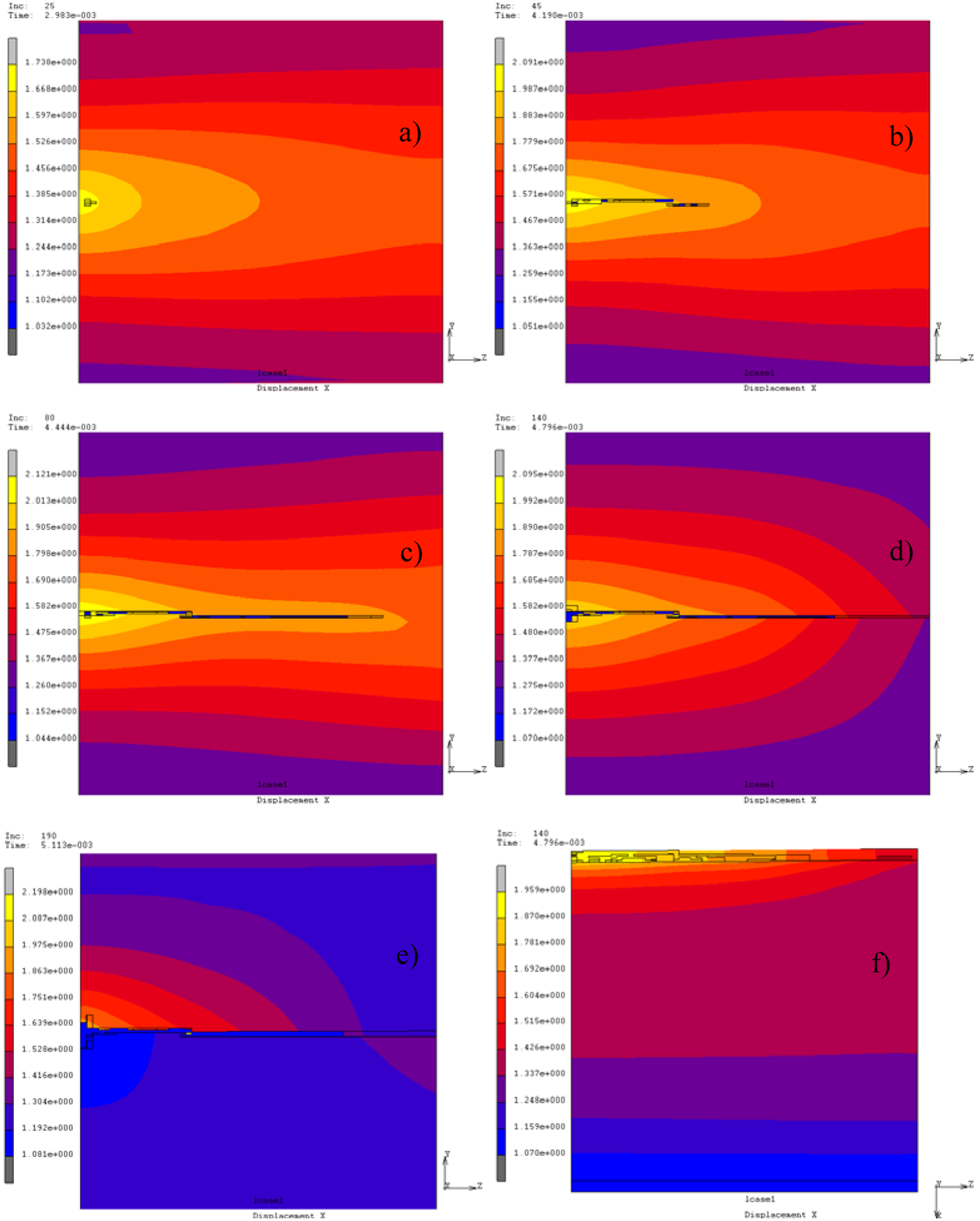
Vertical × displacement contour bands (DN75 top view). Crack opening at 0.002983 s (a), propagation at 0.00419 s (b) and 0.004444 s (c), completion at 0.004796 s. (d). Free vibrations at 0.005113 s (e). Longitudinal section at 0.004796 s (f).
As highlighted by Figure 8(e), when the separation between the two pipe edges is completed the pipe dynamics are modified. A modal analysis confirms a reduction in the pipe natural frequencies from the entire configuration (e.g. first five frequencies: 478, 852, 1350, 1888, 2698 Hz ) to the fractured one (152, 334, 421, 1104, 1300 Hz). Natural mode shape were also affected: irregular oscillations between the edges, at the fracture completion, dominate the vibrational signature of the damaged specimen.
Figure 9 depicts, for both the DN50 and 75 specimens, the time histories responses for the impact mass kinetic energy and work done on the specimen. According to the work–energy theorem, the work done by the impact mass is equal to the change in kinetic energy. It is worth underlining the significant correspondence in the time domain between the fracture propagation (Figure 8(a)–(d) and the energy components variation (Figure 9(b)). Subsequently to the linear deformation in the specimen, and the related quite linear variation in the energy components (0–0.003 s in Figure 9(b)), the fracture opening starts and spreads (Figure 8(a)–(c), dissipating a large part of the energy injected in the system by the impact mass (0.003–0.0048 s in Figure 9(b)). A small part is transferred to the pipe post-impact vibrations. It has been estimated close to 20% through transient analyses on fractured pipe configuration. The material constitutive law and low friction coefficients herein adopted allow the exclusion of alternative dissipation sources.
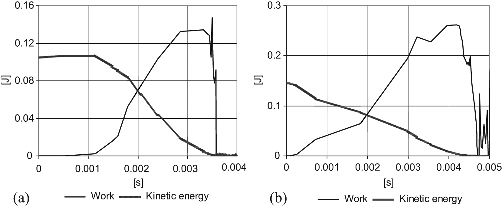
Critical heights: impact mass kinetic energy and work. DN50 (a), DN75 (b).
The kinetic energy of the impact mass at the beginning of the contact (at 0 s in Figure 9(a) and (b)) is of concern since it allows the evaluation of the energy release rate. Such values, once reduced by 20% to take into account the losses owing to post-impact energy transfer, lead to compute 270 J/m2 on the fracture surface. This is compatible with the fracture criterion and objective assumptions in ‘Criterion for element deactivation’.
Conclusions
This article deals with standard impact tests on polypropylene pipes. A methodology for analysing pipes subjected to brittle fractures at low temperatures is developed by means of experimental tests and 3D simulations in a multipurpose FE framework.
Preliminary laboratory tests are performed for characterizing the material compound at different temperatures in quasi-static conditions. Then, pipe samples behaviour under impact loads has been performed by means of dynamic experiments at different fixed temperature. These investigations point out the temperature-dependent response of the material with markedly brittle characteristic at low temperature and high loading velocities, such as those adopted during the dynamic tests. Furthermore, the impact threshold between the complete fracture and the pipe integrity is clearly defined, with negligible variability.
A multipurpose FE code supplies the analysis environment. A Fortran user subroutine implements a procedure able to follow the time–space fracture evolution by the deactivation of FEs using a selective fracture criterion. The crack propagation is modelled by the proposed VCMD method and the numerical results match the laboratory outcomes and the material specifications in terms of fracture toughness.
This study provides useful elements for the simulation of fracture by a straightforward FE methodology when 3D solid elements, high impact velocities and large strains are involved in the analysis. This is achieved without a prescribed crack path and without the use of re-meshing techniques. Moreover, its approach is general and can be employed with all multipurpose commercial FE codes, with the possibility to implement user subroutines and elements deactivation. It represents a valuable numerical method for identifying the integrity of industrial polypropylene pipes, in particular when the visual inspection is not able to detect small damage levels.
Besides these positive results, the proposed methodology is also useful in the optimization process of the material compound, for ameliorating the pipes response to impact loading, implementing a numerical study without performing extensive experimental campaigns.
Footnotes
Acknowledgements
The Author is grateful to Professor Federico Perotti (Politecnico di Milano, Italy) for his stimulating guidance during the development of the dynamic approach; Fabio Scannavino (Project Manager at MSC Software, Genoa, Italy) for his support on MARC MSC code, and Professor Luigi Cedolin (Politecnico di Milano, Italy) for his fruitful discussion on fracture mechanics concepts.
Funding
This research received no specific grant from any funding agency in the public, commercial, or not-for-profit sectors.