
Abstract
Today, tailored welded blank sheets have found various applications in automotive, aeronautic and many other industrial fields. One of the most efficient methods for production of tailored welded blank sheets is application of the friction stir welding process. In the present article, the effect of friction stir welding parameters on the microstructure and mechanical properties of heterogeneous tailored welded blank sheets made from aluminium alloys of types 5083-H12 and 6061-T6 with the similar thickness of 1.5 mm is studied. The considered parameters are rotational speed of the tool, linear speed of the tool, pin diameter and shoulder diameter. In order to come by a tailored welded blank sheet with optimal mechanical properties, response surface methodology, which is considered as a strong tool in design of experiments, has been employed to design the experiment matrix, and the corresponding experiments have been conducted under laboratory conditions. Tensile strength of tailored welded blank sheets are determined as the relation in the mathematical model. The optimal condition and objective effects of parameters are determined via this relation. Data variance analysis showed that rotational speed and diameter tool have the most and the least effect on tensile strength, respectively. Rotational and linear speed are more effective than pin and shoulder diameter in input heat, which is produced by friction.
Keywords
Introduction
The friction stir welding (FSW) process was first introduced by The Welding Institute (TWI) in 1991, as a solid-state welding method. 1 This process, whose schematic has been illustrated in Figure 1, incorporates a rotating tool plunged into two plates positioned and fixed in a fixture in the butt position. The tool traverses the desired path on the joint with constant linear and rotational speeds (of course in some cases of FSW, the tool is linearly stationary and the plates are moved with constant linear speed). During this process, the local heat is generated through the friction between the tool and the work piece. Finally, the generated heat softens the material in the vicinity of the pin and the combination of rotational and translational motions of the tool leads to displacement of materials and stirring of them into each other. The result of this stirring is the joining of the materials in the solid state.
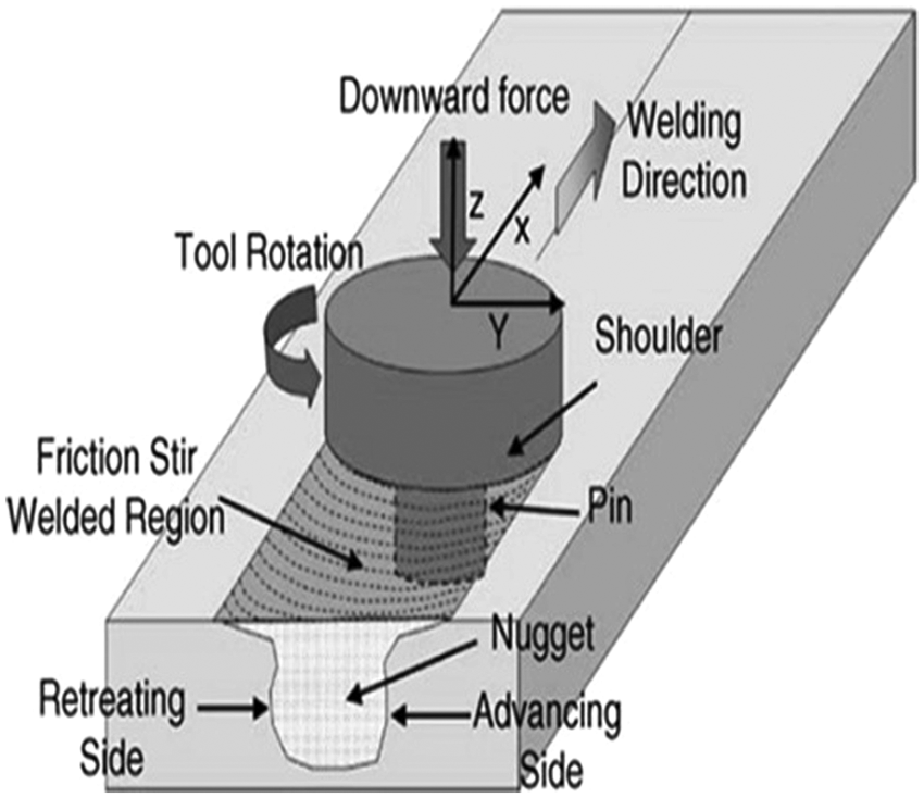
Schematic of FSW. 2
Owing to the low weight and high strength of aluminium alloys and their advanced application in aerospace and automobile industries, joining of this metal has always been under focus. In fact, other welding processes cannot surmount the major problems associated with fusion welding of aluminium alloys. On the other hand, possibility of material waste reduction, alleviation of ecological concerns and avoidance of harmful gases used in fusion welding justify and guarantee application of FSW on aluminium alloys.3,4 Most of the experimental and numerical studies performed on the FSW process have dealt with the effects of different parameters on the final weld quality.5,6 The effects of rotational speed of the tool, 7 linear speed of the tool8,9 and both of the aforementioned speeds10–13 on mechanical properties and infrastructure of the resulted welded joint of the aluminium alloy of the 6000 class have been investigated by researchers. Some researches on the microstructure and mechanical properties of the aluminium group 6000 have been done recently.14,15 Some researchers 16 with some studies on rotational and linear speed and axial force via artificial neural network (ANN) and response surface methodology (RSM) methods and comparing these two methods have surveyed the ultimate tensile strength. Another group 17 performed the experimental tests by design of experiment (DOE) method and in order to predict the tensile strength used the multiple linear regressions. Despite the fact that many works have been reported in the field of FSW, 18 these reports can not solely provide optimal parameters for FSW of the aluminium alloys of type 5083-H12 and 6061-T6. In this welding process, the input parameters, such as welding factors, geometry of the tool and the type of materials to be welded play a significant role in the quality of the joint.
The main objective of the present study is optimization of the FSW parameters in order to attain the highest tensile strength of tailored welded blank (TWB) sheets produced through FSW. This research has tries to deliver a new output in the optimization field by applying DOE method in this process. After elementary experimental tests to recognize the effective parameters on the mechanical attributes of TWB sheets, rotational and linear speed and pin and shoulder diameter are selected in order to survey them. Then with performing the experimental tests, which is dictated according to Box–Benken layout design, the effect of selected parameters on output tensile strength was considered. Finally, after determining the optimal condition that leads to maximum tensile strength, experimental verification is done.
RSM and experiments
DOE and RSM
DOE is a method of collecting the information associated with experiments so as to enable adjustment of controllable variables in an experiment in the best form. 19 RSM, as an auxiliary tool in DOE, has recently found much interest in optimization of engineering problems. This method incorporates a combination of statistical and mathematical techniques for numerical solution of optimization problems. 20 RSM is a method for estimation of the objective function in an optimization problem and finding its optimal solution. This method, in fact, attempts to find a function, which best represents the relation between control and output variables of the experiment, through statistical algorithms, and then, tries to optimize it. In this research, based upon RSM’s Box–Benken design, 29 experiments have been performed, and the results have been utilized in implementation of the RSM and extraction of the mathematical relation between the experimental outputs and inputs. The control variables and their defined intervals are presented in Table 1.
Control variables and their defined intervals.
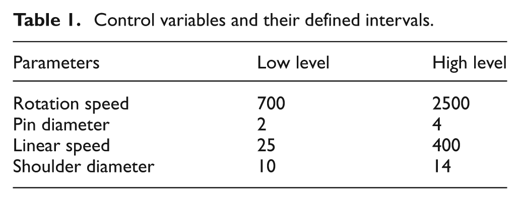
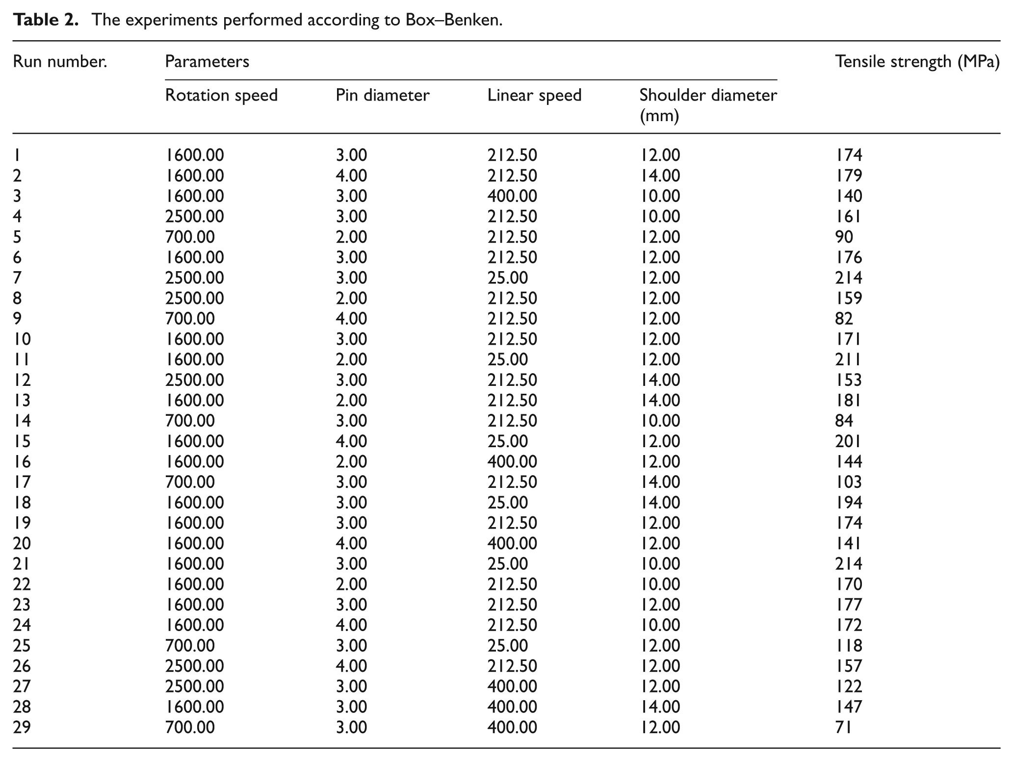
As displayed in Table 1, there are four controllable design variables in this problem, which were considered as effective parameters after initial experiments. Thus, with regard to their adjustment levels and the layout proposed by Box–Benken design, the experiments were performed, whose results are provided in Table 2.
The experiments performed according to Box–Benken.
Materials
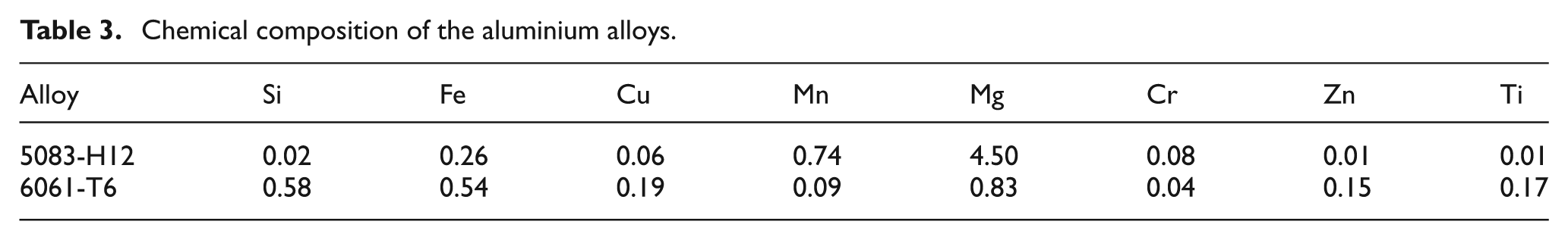
Owing to the welding applicability and formability characteristics associated with aluminium alloys of class 5000 and 6000, welding of these plates has attracted great attention in different industries. Welding of these two classes of alloys, in production of heterogeneous TWB sheets applied in the manufacture of skin sheets of automobiles, is of much interest in particular. Regarding the industrial significance of these alloy classes, this research has focused on the aluminium alloys of types 5083-H12 and 6061-T6. Chemical composition of these alloy classes has been provided in Table 3.
Chemical composition of the aluminium alloys.
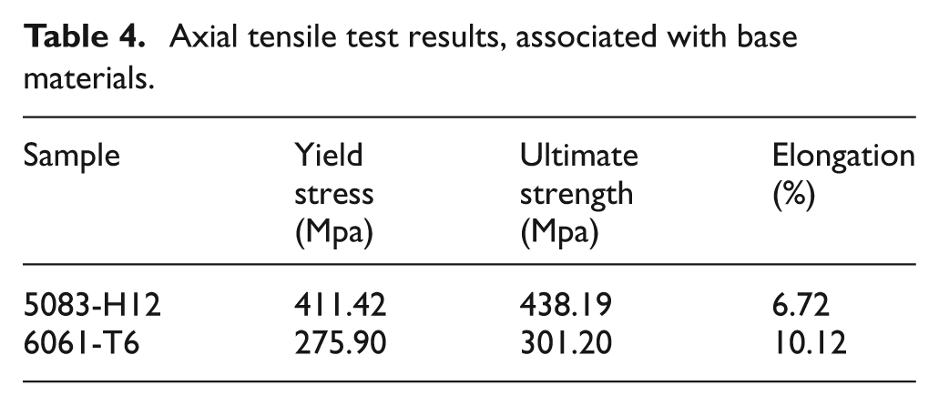
Before performing welding on the samples, in order to make sure about the tensile strength of the considered alloys and compare them with those of welded sheets, axial tensile tests were conducted on the specimens. Tensile test specimens were provided according to ASTM-E8 standard, of the sub size type with the gauge dimensions of 6 mm in width and 25 mm in length. The results of the tensile tests are presented in Table 4. For each alloy, six specimens were tested, whose average is recorded in Table 4.
Axial tensile test results, associated with base materials.
In this kind of welding process, the two sides of the welding line will have different mechanical attributes. These two sides are called retreating side (R.S.) and advancing side (A.S.). In the R.S., the linear velocity vector and the vector tangent to the rotational velocity of the tool are opposite in direction; while in the A.S., the vector of linear velocity and that tangent to the rotational velocity of the tool lie in the same direction. 21 Therefore, the materials located in the A.S. experience longer contact under the shoulder. This contact causes deformed and undeformed material to get larger, so the metallic bond will get higher. Finally these matters will result in higher strength. In fact owing to the lower strength and hardness resulted in the R.S., the thicker or stronger sheet is preferred to be positioned on the R.S. On the basis of the aforementioned facts, the 5083 aluminium alloy sheet is located on the R.S. in this research, owing to the higher strength in comparison with its counterpart.
Experiments
In this work, two sheets made from 5083-H12 and 6061-T6 aluminium alloys with the similar thickness of 1.5 mm were friction stir welded in the direction normal to the rolling direction of the plates, taking advantage of a traditional milling machine. In the welding procedure, the varying parameters were rotational speed (700, 1600 and 2500 r/min), linear speed (25, 212 and 400 mm/min), the tool’s shoulder diameter (10, 12 and 14 mm) and pin diameter (2, 3 and 4 mm). The pin length is another effective parameter that must be set slightly smaller than the thickness of the plates being welded. In this work, the pin length was considered 1.3 mm. H13 steel was selected as the tool material. This tool was first kept at 1000 °C for 13 minutes in a furnace, and then cooled to the room temperature using compressed air. The final temper was performed at 530 °C for one hour in the furnace, followed by cooling in the open air to room temperature and finally the oxides were removed from its surface. 22 The welding tool was tilted at an angle of 2° from the normal direction of the work sheets towards the trailing side of the tool. The penetration depth of the tool shoulder into the plates was considered to be around 0.1 mm. The cone angle of the shoulder’s head (shoulder cavity) is another important tool parameter that was constantly selected as 4° for all the tests in this research. The shoulder cavity, in combination with the tool’s tilt angle, paves the way for compression of annular rings of plasticized materials around the tool, which pushes the material flow toward the pin. 23
After welding of the sheets, incorporating the parameters considered according to Table 2, the appearance of the weld was visually inspected in the first step, followed by inspection of the root and the crown. Afterwards, the surplus of the stirred materials standing out of the weld line was removed. As before, tensile test specimens were prepared according to ASTM-E8 (Figure 2). In machined specimens of TWB sheets, the weld line was located in the middle of the gauge length, and the tension axis was considered in a direction normal to the weld line and parallel to the rolling direction of the plates. The tensile test specimens were machined carefully, and coolants were incorporated to avoid overheating during the machining process. The tensile tests were performed at room temperature with the loading rate of 2 mm/min. In this study, three specimens of each case were tested. However, the ultimate strength provided in Table 2 for each case represents the average value of the aforementioned three specimens.
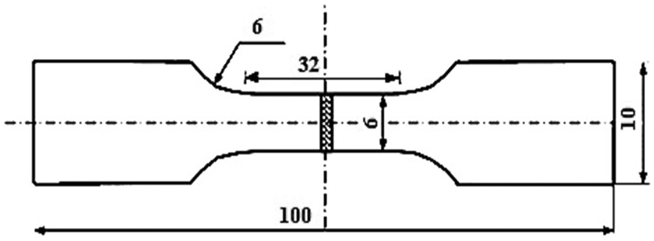
The tensile test specimen prepared according to the requirements of ASTM-E8.
Analysis of variance and mathematical model of the objective function
After performing the experiments and before estimation of the mathematical function, it is required to study the level to which the effects of control variables on the output are significant. Analysis of variance (ANOVA) is applied during studying the effects of the parameters on the objective function. Table 5 displays a statistical summary of the data analysis. In this table, which focuses on regression coefficients (adjusted R2 and predicted R2) and predicted residual error sum of squares (PRESS), the three Linear, 2FI and quadratic models are compared. Owing to having a high level of regression coefficients and the least level of PRESS, the ANOVA proposes the quadratic model for estimation of the parameter effects on the objective function. 24
Statistical summary attributed to analysis of the existing models.
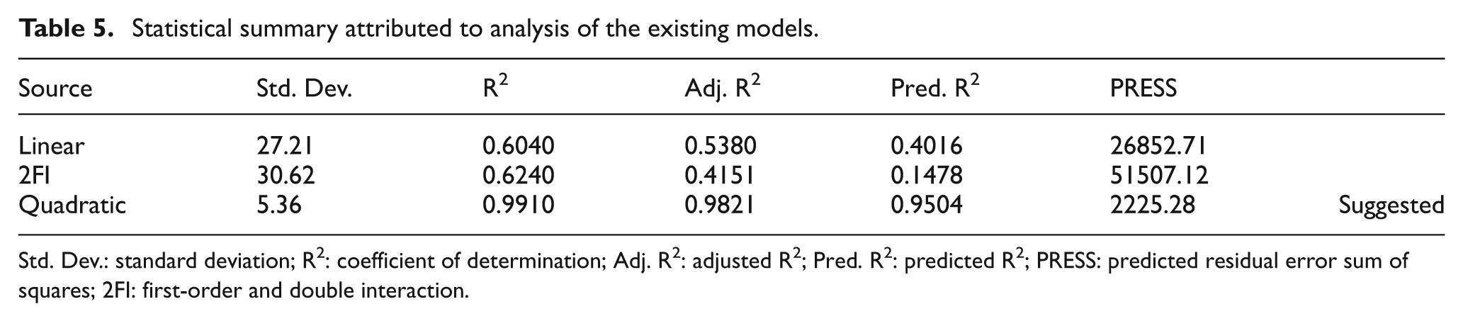
Std. Dev.: standard deviation; R2: coefficient of determination; Adj. R2: adjusted R2; Pred. R2: predicted R2; PRESS: predicted residual error sum of squares; 2FI: first-order and double interaction.
Table 6 illustrates the results of ANOVA of the model and the effectiveness associated with each variable on the output variable (tensile strength). It is noteworthy that if the error occurrence probability (P-value) is less than the acceptable error level (0.05 in this problem), then the effect of the corresponding parameter will be considered as significant. As observed, the value of the error occurrence probability attributed to the model is 0.0001, which is smaller than 0.05, and indicates that the model being studied is significant.
Effectiveness of each variable on the output variable according to the ANOVA.
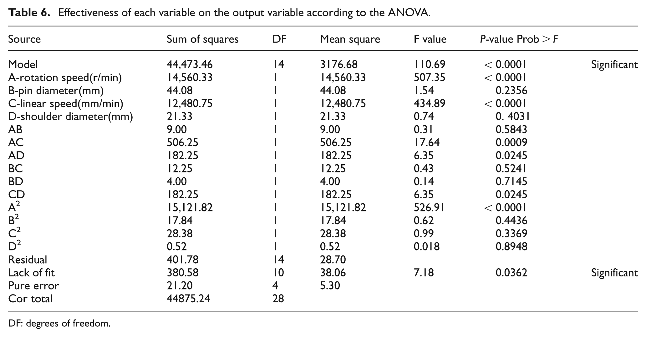
DF: degrees of freedom.
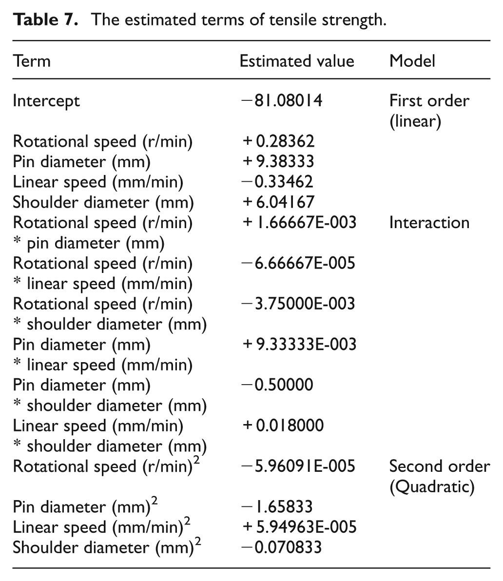
According to Table 6, the effects of the terms A, C, AC, AD, CD and A 2 on the objective function (tensile strength) are significant. Now, as Table 7 shows, the mathematical relation between the inputs and outputs can be estimated taking advantage of RSM method.
The estimated terms of tensile strength.
Analysis of the mathematical model
The coefficient of variation (CV) represents the amount of deviation from the average value of a unit of output. The small value of this quantity in this problem unveils the accuracy of the model. The first two indices are attributed to R2, and represent the fit of the test data on the estimated model, which are more desirable when approaching unity. The adequacy index of the model, Adeq.Precision, indicates the accuracy level in application of test data in building a model, and the more it exceeds four, it is more desirable. The last index reveals the adequacy precision of the model, which shows whether the model is capable of making predictions on other values out of the test limit. Pred. R2 is the correlation coefficient in prediction, which is more desirable when approaching unity. Therefore, the fitted quadratic model is reliable, and can be employed in optimization of the test output. After estimation of this model, its accuracy level can be accessed through various indices. Table 8 provides some of the most important indices for assessment of a statistical model. The significance of the results and the reliability of the expanded mathematical model can be determined through several attitudes. As observed, the adjusted R2 and the predicted R2 coefficients of the model are 0.9821 and 0.9504, respectively, which are very close to unity, and indicate the adequacy of the model. On the other hand, provided that the Adeq.Precision of the model exceeds four, the reliability of the model is signified. Regarding Table 8, this value equals to 36.726.
Most important indices in assessment and accuracy of the model.
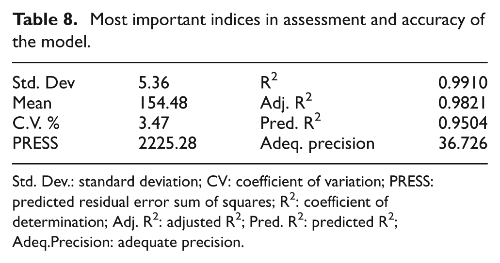
Std. Dev.: standard deviation; CV: coefficient of variation; PRESS: predicted residual error sum of squares; R2: coefficient of determination; Adj. R2: adjusted R2; Pred. R2: predicted R2; Adeq.Precision: adequate precision.
Discussion and the optimal condition
First of all, according to the mathematical model, a schema of relation between inputs and outputs is shown graphically in this section, and then making use of RSM, the optimal strength is calculated and presented. Regarding the fact that there are four independent variables and one dependent variable, five dimensions are to be considered for presentation. For simplicity, the diagram of this function is displayed in a three-dimensional space, in which two of the design variables are kept constant on the mean value of their defined interval, and the variation of the output variable is presented as a function of the two remaining variables.
According to the differences of slopes of surfaces toward each parameter, it should be pointed to this general note that effects of rotational speed, linear speed, shoulder diameter and pin diameter parameters are the most effective parameters on the tensile strength, respectively. This general fact must be mentioned that with the increase in rotational speed, shoulder diameter, pin diameter and reduction of linear speed, the friction, and consequently the input welding heat, increases. Figure 3 illustrates the effects of varying rotational speed and pin diameter, while linear speed and shoulder diameter are kept constant. As presented, the rise in pin diameter and rotational speed leads to higher weld strength. This fact can be attributed to the higher fraction and consequently heat value during welding. Of course, the discussed rise in the strength bears a maximum value, and with increase in the friction over an allowable limit, the weld strength declines. Figure 4 shows the two significant parameters; rotational and linear speed. With increasing rotational speed and decreasing linear speed, the friction rises and the produced weldment has a suitable tensile strength. Increasing the tensile strength via increasing the rotational speed and decreasing linear speed has a limit. It means that if the rotational speed gets too high and linear speed gets less, the friction will be more than the optimal limit; hence the tensile strength will decrease. Solution of the precipitates, such as Mg2si of the aluminium of class 6000 in the welding line and consequently a decrease in tensile strength of the aluminium of class 6000, is the reason of this matter. On the other hand, extra input heat leads to the coarse grained desolated precipitates. In Figure 5, the effect of rotational speed and shoulder diameter on tensile strength is showed. In this figure, the more effectiveness of rotational speed in comparison to shoulder diameter is well showed. It can be seen that in this figure also, the produced friction, tensile strength increase up to a limited scale, and then it gets less. Getting soft in the two base metals and better stir of the two aluminium alloy together is the reason for a better weldment joint and in the end a high tensile strength. Figures 6, 7 and 8 show the effects of parameters (linear speed and pin diameter, shoulder diameter and pin diameter, and shoulder diameter and linear speed) on the tensile strength respectively. The effect of applying the parameters optimally and producing input heat by friction and finally achieving an optimal tensile strength are observable in these figures.
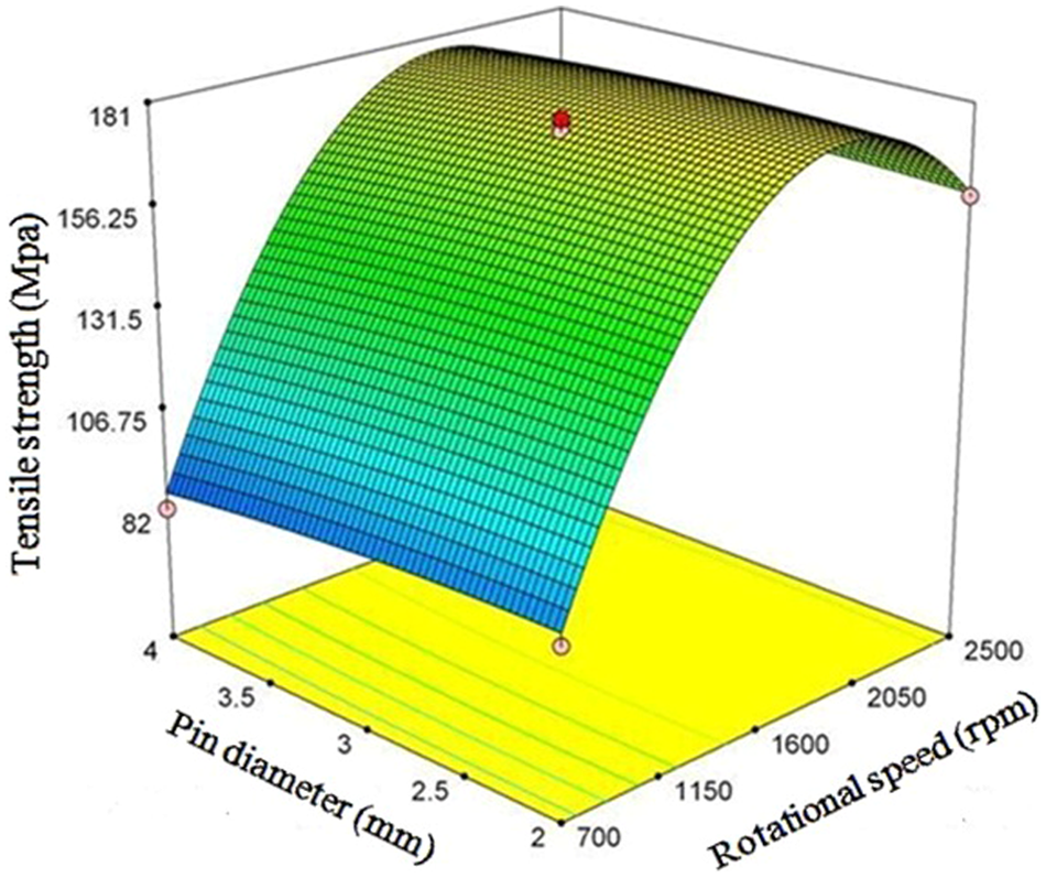
The effects of pin diameter and rotational speed on tensile strength at the constant linear speed of 212.5 mm/min and the shoulder diameter of 12 mm.
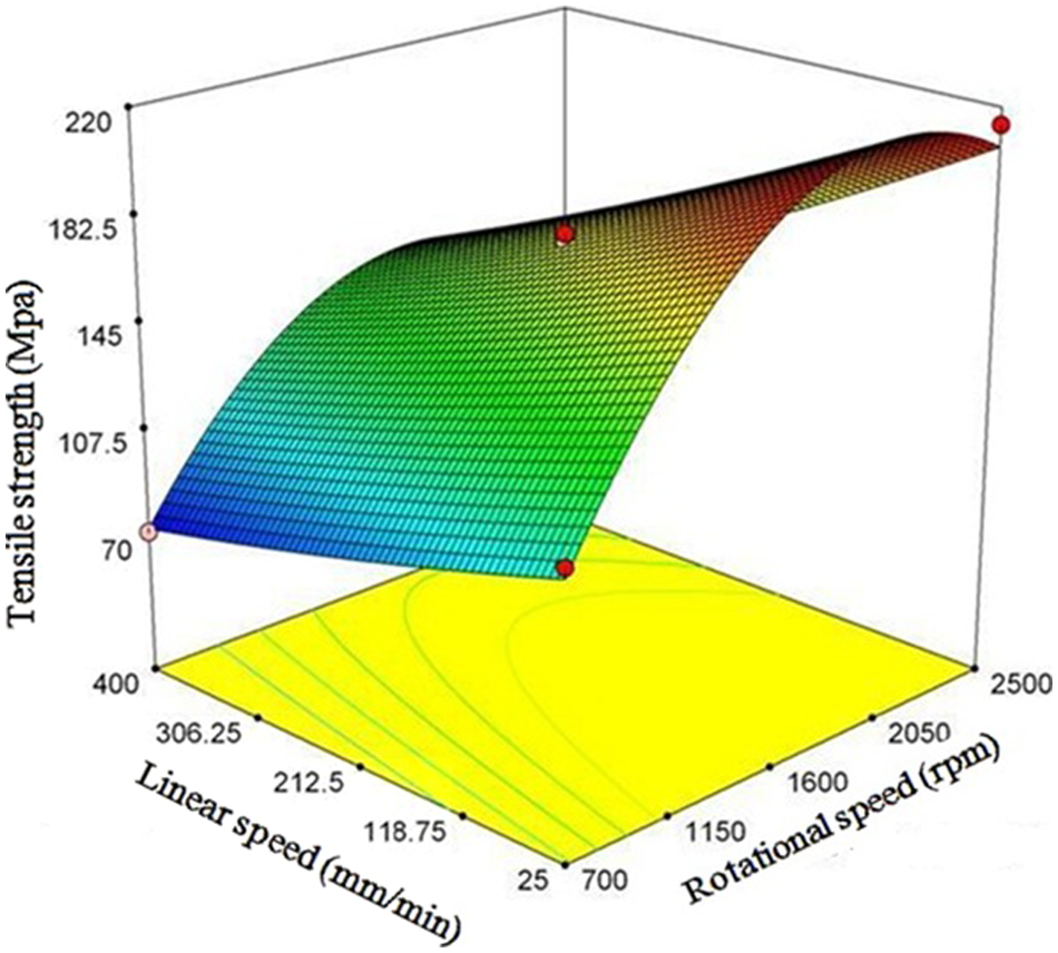
The effects of linear speed and rotational speed on tensile strength at the pin diameter of 3 mm and the shoulder diameter of 12 mm.
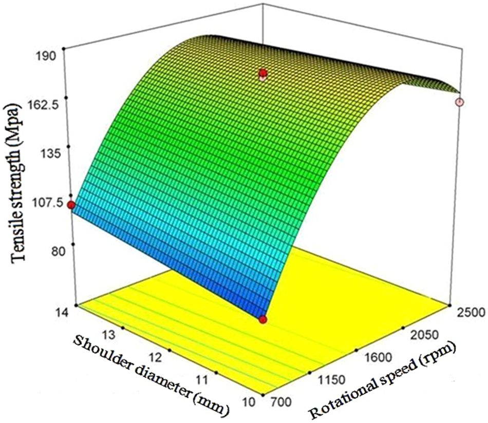
The effects of shoulder diameter and rotational speed on tensile strength at the linear speed of 212.5 mm/min and the pin diameter of 3 mm.
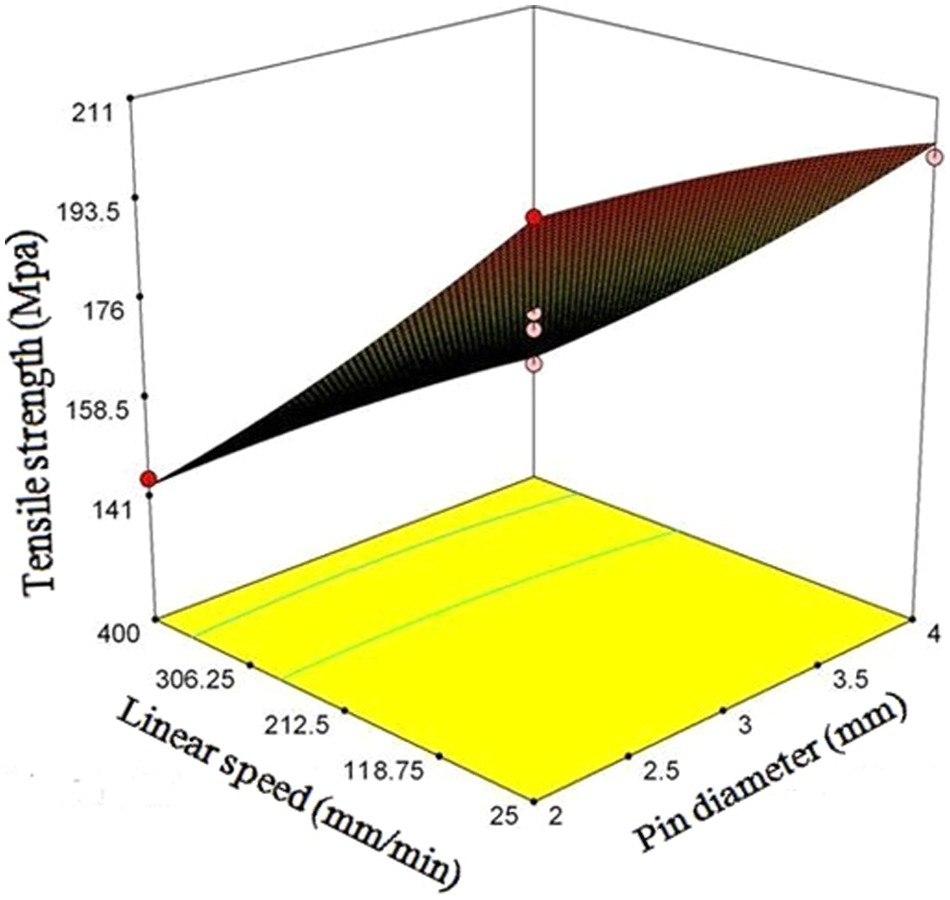
The effects of linear speed and pin diameter on tensile strength at the constant rotational speed of 1600 r/min and the shoulder diameter of 12 mm.
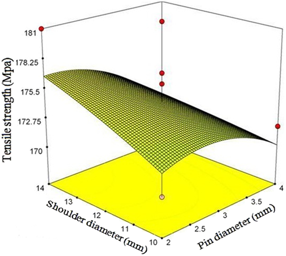
The effects of shoulder diameter and pin diameter on tensile strength at the constant rotational speed of 1600 r/min and the speed rate of 212.5 mm/min.
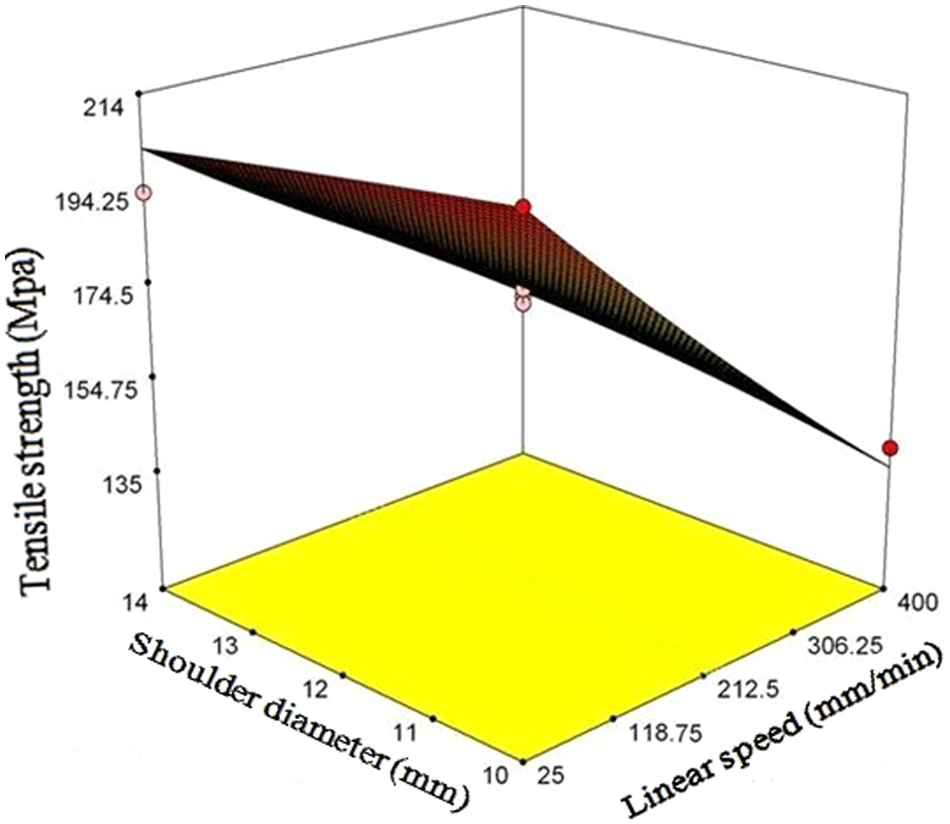
The effects of shoulder diameter and linear speed on tensile strength at the constant rotational speed of 1600 r/min and the pin diameter of 3 mm.
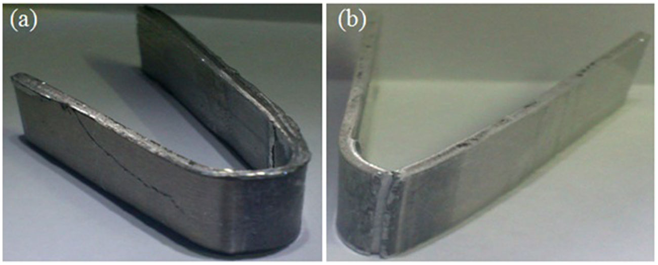
According to the obtained results, the FSW parameters for welding of the two aluminium sheets discussed must be considered optimally. Table 9 displays the optimal parameter amounts for welding of these two alloy sheets in such a way that the resulted TWB bears the highest strength. It should be note that, because of the workshop limitations and having decimal numbers in RSM outputs, putting the outputs of the RSM method in action was not possible in experimental tests, hence it is tried to select the present experimental parameters, which are very close to theoretical parameters. Table 9 shows these theoretical parameters and the replaced experimental parameters.
Theoretical parameters output of the RSM method and the replaced experimental parameters.
Comparison between the predicted strength and the value obtained through experiment unveils negligible error and equal 1.285%, which signifies the reliability of the assessed model.
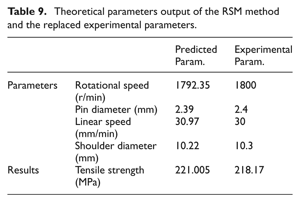
To ensure that the weld section produced by optimal parameters is healthy, the macro etching test is performed on the two samples of optimal weldment. The etching process on the weldment sections is done by helping of the etching solution 15 ml HNO3, 45 ml HCl, 15 ml HF, 25 ml H2O and 15X macrograph. According to Figure 9, superficial and internal defects, such as smashing of the welding, rimming of the welding root, deformed softness phase and crack, is not observable.
Macro etching sections of the optimal weldment. (a) with magnification of 15X, (b) with magnification of 30×.
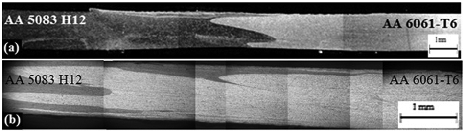
For better comparison of the created joints, micro-graphy sections with magnification of 500× has been delivered in Figure 10. For better contrast creation micro-graphy samples have been etched with 2 ml HF, 2 ml HCL, 5 ml HNO3, 190 ml H2O micro-etch solution. As Figure 10(a) shows, because low heat by friction weld metal does not have good stir, although this joint has no defection in its appearance. Figure 10(b) and (c), shows the suitable stirring in the created joints by optimized parameters.
Micro structures of the weldmetal with magnification of 500×. (a) Unsuitable stirring and cavity defection in weldmetal; (b) and (c) good created stirring in weldmetal by optimal parameters.
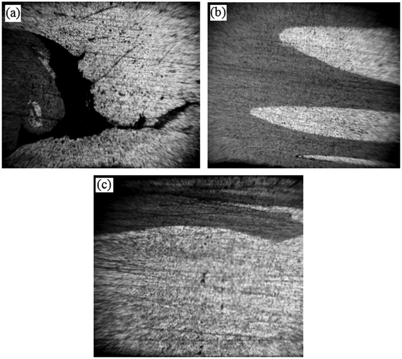
In order to make sure of mechanical properties of the created joints. a root bending test has been conducted on the two joint samples, Figure 11. The created joint with the optimal parameters is under the root bending test and is fully U-form and free of any rupture from the welding root, Figure 11(a). This result shows that with using optimal parameters a perfect joint that has suitable mechanical properties can be produced. One of the produced samples by the parameters that has not created the friction for stirring is shown in Figure 11(b). The created rupture of the welding root shows a joint with root defection and unsuitable mechanical properties.
Root bending test samples. (a) Created joint with good stirring in the weldmetal; (b) created joint with unsuitable stirring in the weldmetal.
Conclusion
According to the theoretical and experimental studies performed in the present work, the following conclusions can be drawn.
Studying the effects of each variable on the output variable reveals that rotational speed is the most effective parameter on the tensile strength of the TWB sheets, manufactured through FSW.
Increase in the input heat in the FSW process leads to more plasticization of the materials and better blending condition, and consequently, stronger joint in the heterogeneous TWB sheets of the aluminium alloys of types6061 and 5083.
An input frictional heat higher than the optimal limit reduces the tensile strength associated with the heterogeneous TWB sheets of the aluminium alloys of types 6061 and 5083. This fact is owing to dissolution of the precipitates present in the aluminium alloy of the 6000 class and creation of coarse grains of the precipitates insoluble in this alloy class.
Rotational speed and linear speed of the tool are more effective than the tool’s pin and shoulder diameters in creation of friction, and consequently input heat, in the weld line.
Conformability of the predicted results and experimental outputs shows the sufficiency of the present model and this matter implies the high appliance of RSM technique in optimizing the FSW process.
The optimal produced weldment macro etching shows the healthiness of the welding that is produced by optimal parameters.