
Abstract
In recent years, topology optimization has been actively researched in computer-aided mechanical part design. However, practical applications of topology optimization to mechanical part design are still very limited in today’s industries. One of the major reasons is that current topology optimization methods always have the tendency to generate hollow and framework-like structures. These structures are very difficult to interpret and most often not directly manufacturable or not manufacturable at all. In this study, a multi-directional constrained method is developed for topology optimization so that topologies of optimized structures similar to mechanical design could be generated. The main objective of this method is to ensure that mechanical parts generated from topology optimization will be simple and manufacturable. Since there is a large diversity of manufacturing technologies, the proposed method allows the customization of constraint directions so that different manufacturing technologies may be catered for. In the proposed method, a modified solid isotropic material with penalization scheme is used for the topology optimization. To demonstrate the effectiveness and usefulness of the proposed method, a number of sample studies have been presented. Even though the proposed method is currently implemented only for two-dimensional case studies, it will be extended to three-dimensional applications in the future.
Keywords
Introduction
Topology optimization has its origin in structural design and has attracted more and more attention from researchers in mechanical design in recent years. There are reports about practical applications of topology optimization in aerospace, 1 automotive, 2 and prosthetics engineering, 3 etc. Some commercial computer-aided engineering software has embedded topology optimization as a standard function. Take ANSYS as an example, it is capable of solving simple minimum compliance problems, 4 this has resulted in some applications of ANSYS for mechanical part designs. 5 However, ANSYS has no functions to guarantee the optimized results will be manufacturable. In fact, current topology optimization methods have the tendency to generate hollow and framework-like features in the optimized design. These features are normally complicated, and most often not directly manufacturable or not manufacturable in a cost effective way. Furthermore, results from topology optimization are often very difficult to interpret, and the conversion of optimized results into computer-aided design (CAD) models is currently a painstaking and manual process.
To generate sensible mechanical parts from topology optimization, efforts had been made to integrate manufacturing constraints into the structural optimization processes. Zuo et al. 6 had considered minimum feature size and geometric symmetry as manufacturing constraints. A hybrid of moving asymptotes and wavelets had been used to solve the topology optimization problem. Chang and Tang 7 had considered the cost of manufacturing in their optimization process. Niclas 8 and Zhou et al. 9 had considered draw direction or draft angle as simple manufacturing constraints. Harzheim and Graf 10 have reviewed optimization methods for cast parts. Even more, some optimization software has been reported to incorporate manufacturing constraints for the casting process. 11 All previous studies have only considered constraints for a specific manufacturing technology. The constraints are generally not universal for all kinds of mechanical parts optimizations and most commonly used manufacturing technologies. In this study, a general set of manufacturing constraints will be investigated. The constrained topology optimization method presented in this article will be applicable and customizable to most commonly used manufacturing technologies. The optimized mechanical part design will be manufacturable and have the stiffest structure.
In most popular manufacturing technologies, such as machining, casting/molding, or forging, etc., there are some primary directions, for instance, the tool approach directions for machining, parting directions for casting/molding, and punching direction for forging. Geometric features of a part design should be properly aligned with these directions in order to be manufacturable. Inspired by this observation, this study proposes and implements a multi-directional constrained topology optimization method for mechanical part designs, so that such designs could be made by commonly available manufacturing technologies. The targeted part topology in this article will meet the requirements of design for machining, design for casting, design for forging, and design for shaping. These manufacturing technologies are popular for making parts/assemblies with both simple and complicated geometry.
For all manufacturing technologies, manufacturability in a cost effective way is almost a common requirement. Take casting as an example, cavities that are not lined up with the parting direction of the die cannot be manufactured cost effectively. 12 Drilling is a time consuming process. It is impossible to drill a hole with an inner diameter larger than an outer diameter. 13 For forging, deep cavities are unreachable. It cannot deal with cavities that have larger inner dimensions and smaller outer dimensions either. For shaping and forming processes, there are no simple and cheap ways to deal with cavities. 14 As a summary, five types of undesired features are shown in Figure 1 (they are shown as two-dimensional (2D) here and will be extended to three-dimensional (3D) in the near future). With reference to Figure 1, the following guidelines for mechanical part design should be followed.
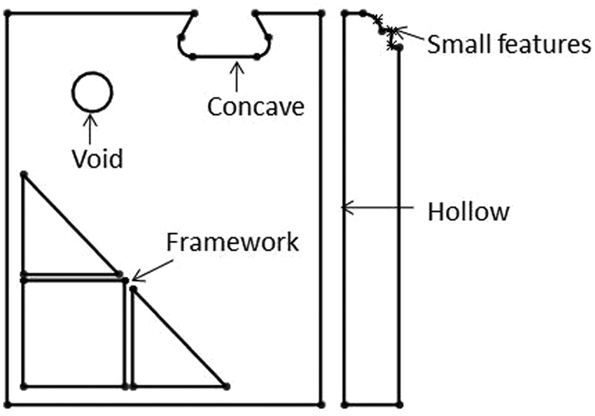
Five types of undesirable features in a mechanical part design.
If hollow features are not essential, they should be prevented in general.
For better manufacturability, the open side of concave features should be larger than their inner part.
It is desirable that framework-like structures should be eliminated, because it is always very difficult to manufacture such structures cost effectively using common manufacturing technologies.
It is common for topology optimization methods to generate internal voids. Since such voids are not manufacturable, they must be avoided in the optimization results.
Small features should be prevented as well, since precision manufacturing is always difficult and expensive for such features.
One of the main objectives of this research is to propose a set of constraints for topology optimization so that the above-mentioned features will not be generated in the optimization results.
Over the years, a number of topology optimization schemes have been reported. They include solid isotropic material with penalization (SIMP), 15 evolutionary structural optimization (ESO), 16 genetic algorithms (GAs), 17 particle swarm optimization (PSO), 18 and level set methods. 19 Each scheme has claimed some merits over others. According to Rozvany, 20 level set and PSO methods have good potential for topology optimization; take PSO for example, its advantages over SIMP are obvious in some aspects. 21 However, in industry, they are still far from actual applications owing to their performance stability. Also presented by Rozvany, 20 the disadvantage of GA-based topology optimization is obvious too because it becomes prohibitively expensive for large systems. ESO is fully heuristic, computationally rather inefficient, methodologically lacking rationality, occasionally unreliable, with highly chaotic convergence curves. Meanwhile, Zhou and Rozvany 22 found that ESO breaks down if the sensitivity, with respect to element density, changes rapidly over finite density variations. Among all the above mentioned methods, the SIMP scheme is the most developed and widely used in practical applications. Because the SIMP scheme is also very fast and stable, the authors will incorporate the proposed multi-directional constraints concept into the SIMP scheme in this research.
The basic concept
Topology optimization is a finite element-based method. Each element has a material density ρ. If the density of an element is smaller than a threshold value, it may be treated as void. To eliminate the five types of undesirable features shown in Figure 1. This article proposes a directional constraint-based SIMP topology optimization method. The general concept is that material density closer to the growth surface is always larger than that farther away from the growth interface. Let ρ i be the density of an element. Assume element i is closer to the growth interface than element j. based on the above description, the constraint can be simply put as ρ i > ρ j . The following will show how the five undesirable features could be eliminated by the simple constraint in topology optimization.
In Figure 2(a)–(e), two elements along each growth direction are shown. The growth direction is indicated by the arrow line that emanates from a growth interface. Figure 2(a) shows a concave feature that will not appear with the proposed constraint as ρ i is smaller than ρ j , which is against the constraint. The same also obviously applies to Figure 2(b)–(d). Sometimes, the optimization result may have a rugged surface, as shown in Figure 2(e), if no constraints are added. This could be eliminated by adding constraints in two orthogonal directions, as shown in Figure 2(f). For example, if ρ m is smaller than ρ n , the constraint will be violated. The proposed method is described in more detail in the following section.
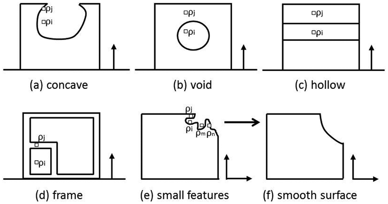
Elimination of undesirable features.
Unidirectional constraint
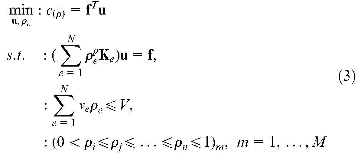
First, the normal formulation of a topology optimization problem, with minimum compliance as the objective and volume of material as the constraint, can be expressed as
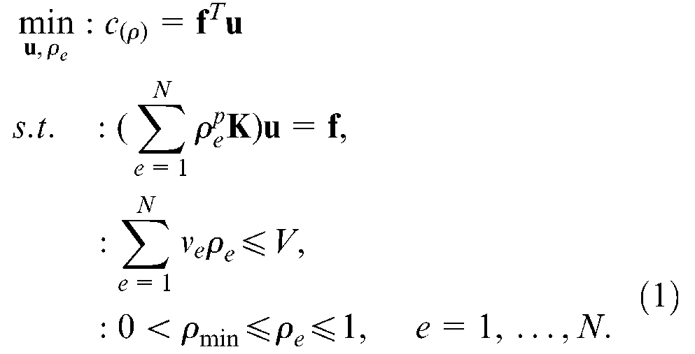
where c(ρ) represents the objective function and the compliance of the structure,
As mentioned in the introduction, the traditional formulation of topology optimization as shown in equation (1) has the tendency to generate hollow and framework-like features. To avoid the generation of these features, a density constraint in the specified growth direction is proposed. Take the unidirectional constraint shown in Figure 3 as an example, let the bottom edge of the design domain be the growth original surface. If the elements’ density along the growth direction is decrement, the tendency to generate hollow and framework-like features inside the optimized structure will be avoided. In other words, the optimized structure is generated by growing up along a prescribed growth direction only. The relative density ρ is gradually decreased along each growth direction.
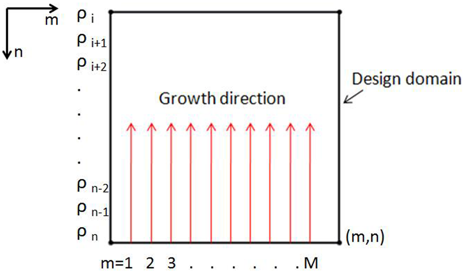
Schematic diagram of a unidirectional growth constraint.
For simplicity, the design domain is assumed to be rectangular and discretized by finite elements. The above description can be represented as the following constraint

where ρ i , ρ i + 1, …, ρ n represents element densities along a growth direction, n is the total number of element in the growth direction, and m is the index of elements perpendicular to the growth direction as shown in Figure 3.
Based on the constraint defined by equation (2), material elements that are far away from the growth original surface will always be removed first if needed. This unidirectional growth constraint method is the basis of the proposed multi-directional constraint method. The growth original surface here will be redefined as the growth interface in multi-directional constraints.
Optimization method
Considering the unidirectional constraint, the topology optimization problem is formulated as
This optimization problem could be solved using the SIMP scheme and the standard optimality criteria (OC) method is chosen as the optimizer. The formulation of this optimizer is shown as 23
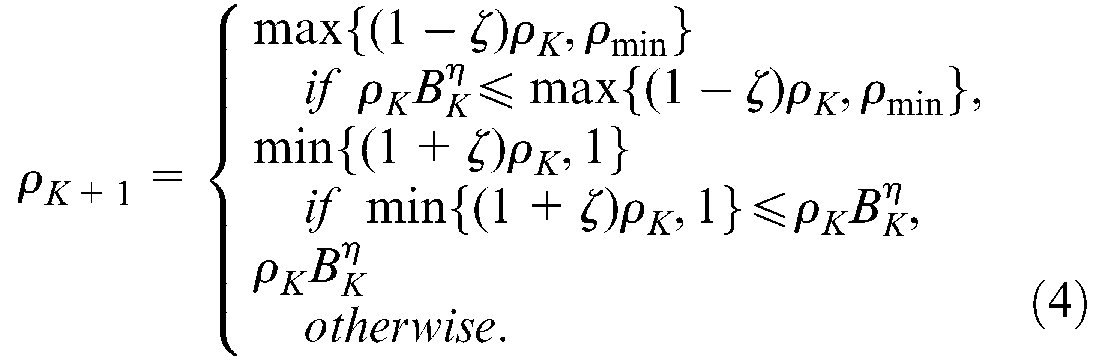
where the variable η is the damping coefficient and ζ is the move limit. Their values are determined by experiments. Based on Bendsoe and Sigmund, 15 the typical values of η and ζ are 0.5 and 0.2, respectively. Experiments have shown that rapid and stable convergence could be obtained by using these two typical values. Then B K is expressed as

where λ is a Lagrangian multiplier that is used as a criteria to filter elements. In this study, a bi-sectioning method is used to find its value.
∂c/∂ρ e indicates the sensitivity of compliance c and can be obtained as
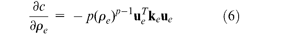
Generally, this optimization scheme uses a specific strain energy λ as criteria. Elements with a strain energy higher than this value (also when B K > 1) will be reserved, otherwise, the elements will be marked as void elements.
Multi-directional constraints
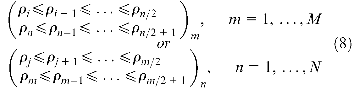
On the basis of unidirectional constraint, multi-directional constraints could be added. First, constraints in two opposite directions are expressed as
where ρ i , ρi+1, …, ρ n represent densities of elements, n is the total number of element in the vertical direction, and m is the index of elements perpendicular to the growth directions as shown in Figure 4. This constraint ensures that elements nearer to the growth interface always have a larger density value compared with those further away from the growth interface.
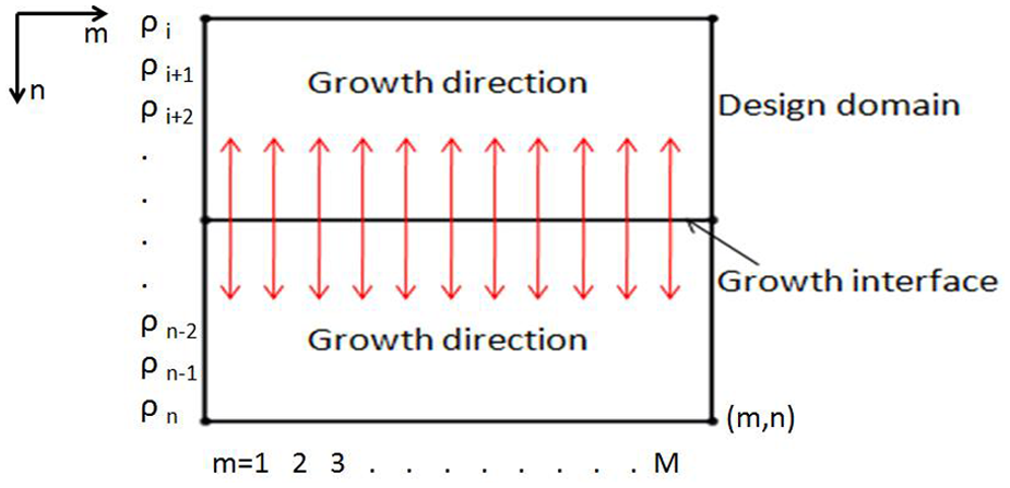
Schematic diagram of two-directional growth constraint.
This constraint is especially good for generating parts that are to be manufactured by general casting/molding processes (without the need of side cores). In the casting/molding process, part features should line up in the draw direction of the die/mold in order to meet parting requirements. The two-directional constraints defined in equation (7) will ensure that parts generated can be casted or molded with parting directions the same as the growth directions. This will be illustrated by a number of sample studies presented in the next section.
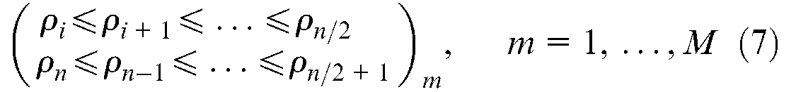
The two-directional constraints can only be used to generate casting or molding parts without the need of side cores. Four-directional constraints, with reference to Figure 5, can be formulated to meet more general requirements of casting or molding processes. The formulation is as
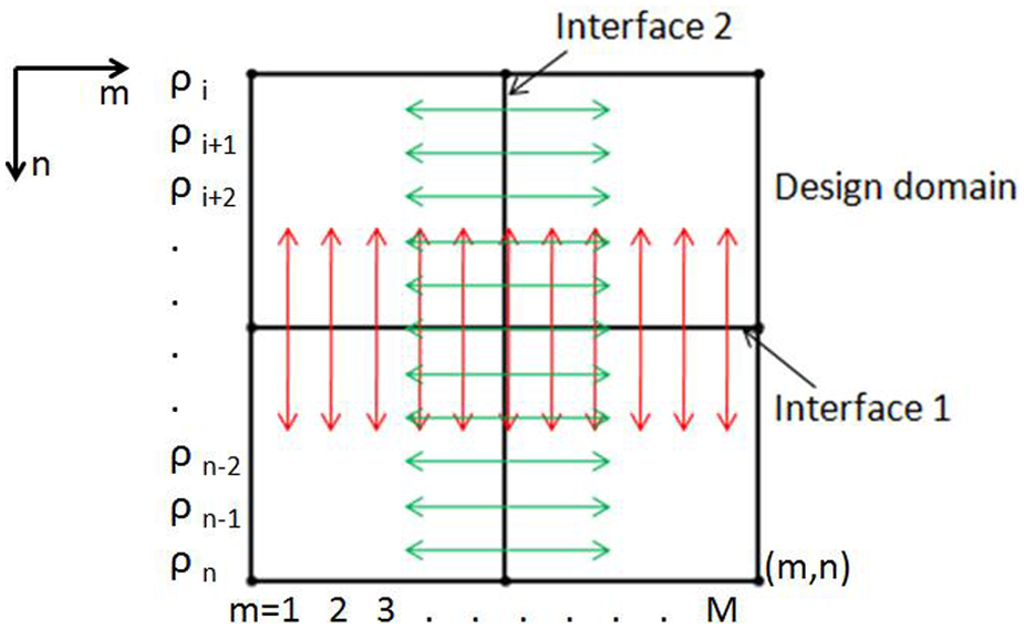
Schematic diagram of four-directional growth constraint.
The first part of the formulation is the same with the two-directional constraint. The second part just takes the horizontal direction as the growth direction against interface 2 as in Figure 5; other terms are not changed compared with the first part. Where ρ j , ρj+1, …, ρm/2 represent densities of elements that are along the same growth directions from left edge to interface 2, ρm/2+1, ρm/2+2, …, ρ m represent the element density from interface 2 to the right edge. n and m are the number of elements along the vertical and horizontal directions, respectively. This method takes the vertical and horizontal central planes of the design domain as growth interfaces, and then the structure grows along four directions when optimized with minimum compliance.
Four-directional growth constraints can ensure that parts generated could be manufacturable by most manufacturing technologies. The growth constraints ensure that an element density is always higher when the element is nearer to the growth interface. In other words, the inner elements in the design space always have higher density. This constraint could avoid the generation of the undesirable five types of features depicted in Figure 1.
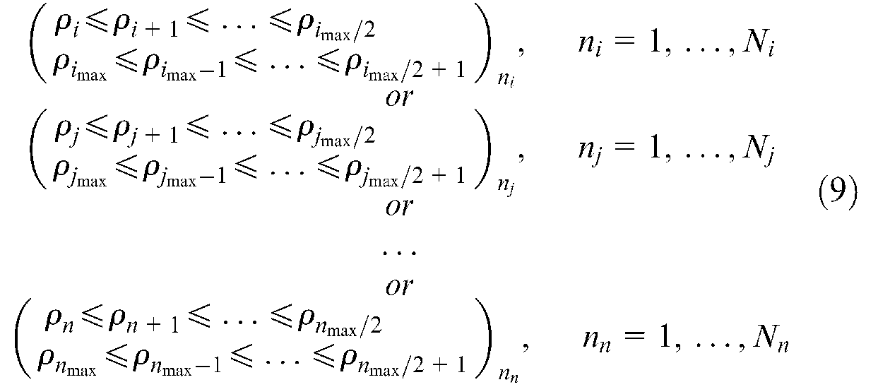
Since the five types of undesirable features can be avoided in the topology optimization process, parts generated could be easily manufacturable by common manufacturing technologies, such as machining, casting, and forging. If users have special requirements on certain directions, the multi-directional constraint method, as formulated in equation (9), can be used
where ρ
i
, ρ
j
, …, ρn represent elements densities along each growth direction, ρ
i
, ρ
j
, …, ρ
n
represent the number of sets of elements perpendicular to each growth direction.
This multi-directional constraint method can be explained clearly by Figure 6. The number and location of growth interfaces could be chosen by customers, they could choose one, two constraint directions, or even more constraint directions. This facility is useful for part designs tht have manufacturing constraints in special directions. For example, if some mechanical parts have manufacturing constraints on diagonal directions, the four diagonal directions are chosen as constraint directions, as shown in Figure 7. Then the part design after topology optimization will be manufacturable along the four diagonal directions. The number and location of the growth interfaces can be defined by users.
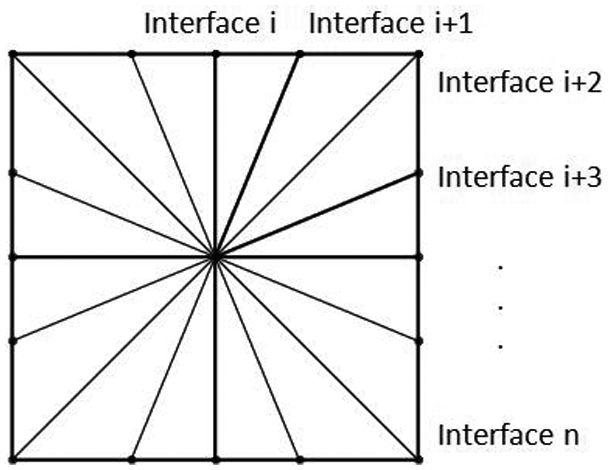
Schematic diagram of multi-directional growth constraint.
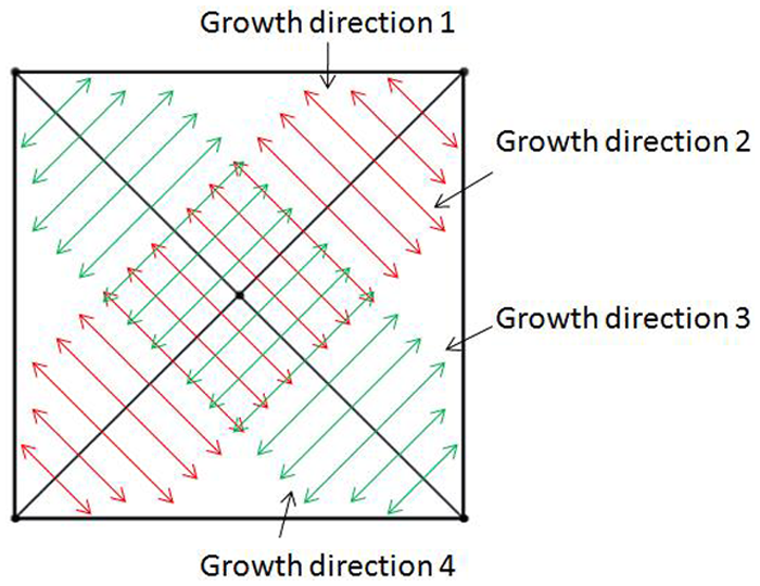
Diagonal growth constraints.
Sample studies
Based on the above presented directional constrained topology optimization method, a number of sample studies are presented here. Because the samples in this study are all 2D, it is assumed that the part cannot be processed from directions outside the 2D plane. The sample studies have shown that the proposed method can generate better results compared with the one without constraint in terms of manufacturability and simplicity. The interface position for all the following samples are defined as the geometrical center or the central axis of the design domain.
Sample study one
The design space and load condition shown in Figure 8(a) is a classic example frequently used in testing topology optimization methods. The left edge of the design space is fixed, and a load is applied at the middle point of the right edge. The material volume is constrained to 50% of the design domain. The optimization results without constraint, with two-directional constraints, and four-directional constraints are shown in Figure 8(b), (c), and (d), respectively. From the figures, the optimization results have quite different topologies. The result without constraint has a complicated frame-like structure, which is difficult to manufacture. It is not suitable for mechanical design where simplicity is very important. The compliance value of this structure is 15.06. Figure 8(c) shows the result from bidirectional constrained topology optimization (constraints are added as those shown in Figure 4). The line indicates the growth interface, and the arrow lines represent the growth directions. The optimized structure shown in Figure 8(c) has the simplest topology that is commonly used in mechanical design. However, its compliance value of 28.07 is almost twice as much as the one without constraints (15.06). This is not desirable as not much material is saved with the optimization result. Having done a large number of tests with two-directional constrained optimization, the authors have found that all optimization results under two-directional constraint have solid and simple structures with a much higher compliance value than that from without constraint. Therefore, two-directional constrained optimization in the following samples will not be presented and discussed. For four-directional constrained topology optimization, as shown in Figure 8(d), the constraints as shown in Figure 5 have been added. The constraints are also shown in Figure 8(d), where the lines indicate the growth interfaces and the arrow lines represent the growth directions. The optimized structure has an easily manufacturable part topology, with a similar compliance value (15.02) to the one without constraints. Therefore, the result shown in Figure 8(d) is more preferable in terms of mechanical design. It can be seen that the part shape in Figure 8(d) is much simpler than that in Figure 8(b) and the material saving rate is almost the same.
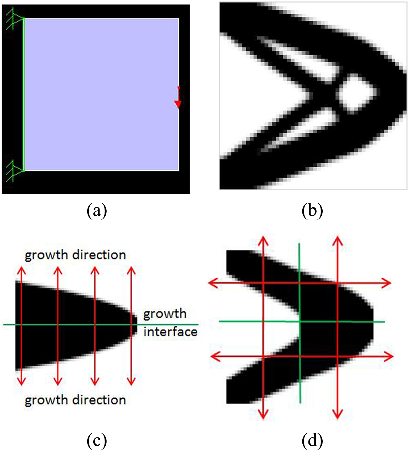
Sample study one. (a) Boundary and load condition; (b) optimization without constraints (compliance = 15.06); (c) optimization with two-directional constraint (compliance = 28.07); (d) optimization with four-directional constraint (compliance = 15.02).
Sample study two
The load, boundary conditions, optimization results without constraints, and optimization results with four-direction constraint are shown in Figure 9. The material volume for both conditions is constrained to 50% of the design domain. Compare the two results in Figure 9; the constrained one in Figure 9(c) has a much moe simple structure with a compliance value of 27.35, which is only slightly higher than the one without constraints (26.67). Again, it can be seen that the result in Figure 9(c) is more easily manufacturable and its geometry is much simpler.
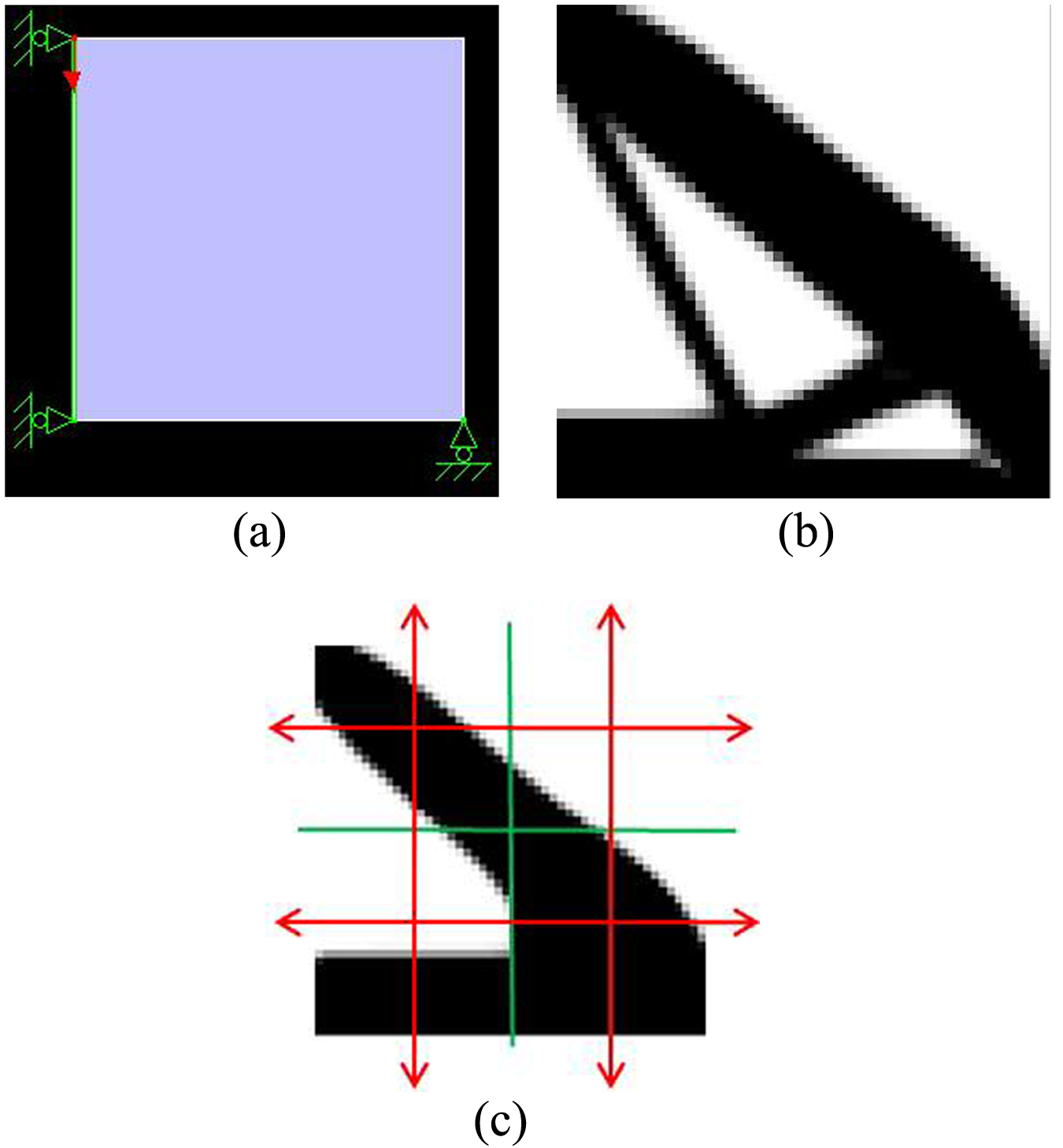
Sample study two. (a) boundary and load condition; (b) optimization without constraints (compliance = 26.67); (c) optimization with four-directional constraints (compliance = 27.35).
Sample study three
The four diagonal direction constraints as shown in Figure 7 are chosen as growth directions in this sample. The boundary and load conditions are shown in Figure 10(a). The material volume is constrained to 40% of the design domain. Results without and with the specified four-diagonal constraint are shown in Figure 10(b) and 10(c), respectively. These two results have similar topology and compliance values; moreover both of them satisfy the diagonal constraints. This is a very special case because the four support points of the design space are co-incident with the diagonal growth directions. This case study shows a special situation where optimization results are similar with or without constraints.
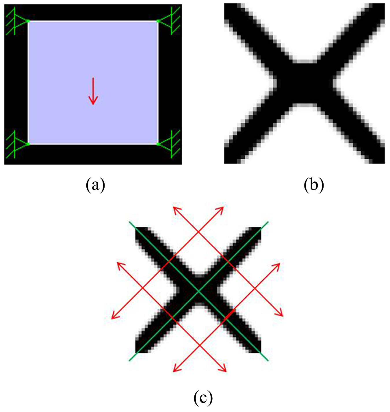
Sample study three. (a) Boundary and load condition; (b) optimization without constraints (compliance = 4.00); (c) optimization with four-diagonal constraints (compliance = 4.10).
Sample study four
Figure 11(a) shows a design space under a torsional load. The material volume is constrained to 20% of the design domain in topology optimization. The result without constraint is a frame-like structure, as shown in Figure 11(b), which is undesirable for mechanical part design as it is more difficult to manufacture. After four-directionl constrained topology optimization (constraints are added as in Figure (5)), the result as shown in Figure 11(c) has a simpler geometry. Its topology is similar to a practical spanner design.

Sample study four. (a) Design space and load condition; (b) optimization without constraints (compliance = 261.89); (c) optimization with four-directional constraints (compliance = 263.45).
The above sample studies have shown that optimization results with constraints are quite different to the results without constraint (unless when the growth directions are in the fixed point directions, as in sample study 3 where the two results have similar topology). In general, the proposed constrained topology optimization method can generate parts that have much simpler topology and are more easily manufacturable without large change of the compliance value. In some cases, such as the one in sample study four, the optimization result bears a similar topology design to that in practical applications.
Discussions and conclusions
From the sample studies, it can be seen that the proposed multi-direction constrained topology optimization is capable of producing mechanical parts that are both practical and easily manufacturable. In most cases, four-direction constraints are good enough to generate a simple part topology that is easily manufacturable. The proposed method also makes provision for customized choice of constrained growth directions. For further study, the following will be investigated.
To extend the proposed multi-direction constrained topology optimization method to 3D part design.
To compare the current results with that from the evolutionary method-based structural topology optimization (ESO).
To develop methods for automatic construction of CAD models based on results from the constrained topology optimization.
Footnotes
Funding
This research has been supported by a CRCG grant from The University of Hong Kong.