
Abstract
The experimental research presented in this article explores the wire electrical discharge machining of Monel 400 alloy. An L-18 orthogonal array has been used for experimentation by considering machine controllable factors (i.e. wire tension, pulse-on time, pulse frequency, peak current and servo voltage) and machine uncontrollable factors (namely flushing nozzle height, workpiece thickness and corner angle) as process parameters. Using Taguchi methodology, the influence of the process parameters on the responses, such as material removal rate, surface roughness and corner error, were studied. The impact of pulse parameters modification in corner accuracy improvement has been analyzed. Finally, using Taguchi’s additive model predictions and Pareto optimality approach, a sample technology table for a specific machining condition has been reported for ready use.
Keywords
Introduction
Monel 400 alloy (chemical composition by wt%: 0.047 C, 0.172 Si, 1.03 Mn, 0.012 P, 0.01 S, 0.1 Cr, 0.1 Mo, 1.66 Fe, 0.029 V, 0.1 W, 29.24 Cu, 0.01 Al, 0.103 Co, 0.1 Nb, 0.047 Ti, 0.031 Mg and 67.4 Ni) possesses excellent corrosion resistance, toughness and cryogenic properties. This alloy has many industrial applications, such as ultrasonic machine tools, ship building, nuclear, petroleum, chemical, aerospace, pharmacy, missile, pumps, shafts and valve industries. The conventional machining of Monel 400 alloy is very difficult as it has a tendency to work hardening. The work hardening leads to cutting tool failure and results in a poor process performance. In certain circumstances, stress relieving heat treatments are required to minimize the degree of work hardening. Wire electrical discharge machining (WEDM) is one of the promising machining methods to process Monel (400) alloy to any complex shape with very high precision and accuracy.
It is a well known fact that the material removal mechanism of WEDM is a complex, stochastic and time-varying process involving many variables that make it extremely difficult for setting an optimal parameter setting, even for a highly skilled operator with a state-of-the-art WEDM. Many attempts1–7 have been made to solve this problem. Puri and Bhattaharyya 5 minimized the corner inaccuracy in the trim cutting operation using Taguchi methodology. Sarkar et al.6,7 calculated the wire offset value and used it as an input parameter to enhance the dimensional accuracy of the product. Hsue et al. 8 proposed the concept of discharge-angle by investigating the fundamental geometry properties in corner cutting. Sanchez et al. 9 described a hybrid computer-integrated system for corner accuracy improvement that combines experimental knowledge of the process and numerical simulation. This system allows the user to select the optimum cutting strategy, either by wire path modification or by cutting regime modification. Yan and Huang 10 claimed improvement in corner accuracy using an online closed-loop wire tension control system. Sanchez et al. 11 studied the corner geometry generated by the rough cut, followed by the finishing cuts by considering different aspects, such as work thickness, corner radius and number of trim cuts. A corner error simulation method was proposed by Fuzhu et al. 12 to predict the actual corner profile under different cutting conditions. Dodun et al. 13 enumerated the sharp corner errors in terms of influencing factors during WEDM of thin parts. An effective wire-compensation scheme was developed by Lin and Liao 14 to specify the wire location matrices to improve the precision of the components with tapered features or complex profile. Sarkar et al. 15 developed an analytical model to measure gap force intensity and wire lag under any given machining condition.
It is already established5,15 that the total deflection of the wire (wire lag) is strongly dependent upon the workpiece thickness, gap between the workpiece surface and wire guide (flushing nozzle height), wire tension and the gap force intensity. During sharp corner or curved profile cutting, the mismatch between the wire position and guide position (wire lag) leads to huge geometrical and corner inaccuracies. The corner error at the die is much higher than the punch, as illustrated by Sarkar et al. 15 Nonetheless, little or no attempt has been made on the die corner accuracy. Most of the previous work reported in the literature1–8,10,12 dealt with one fixed workpiece thickness. Until now, no work has been reported on the influence of workpiece thickness along with the flushing nozzle height (gap between the workpiece surface and wire guide) on the responses, such as material removal rate, surface roughness and corner error. Further, it has been learnt that two strategies have predominantly been used to improve the corner accuracy. The first strategy is to modify the cutting parameters (pulse-on time, pulse-off time, peak current, etc.) in order to reduce the wire deflection.5,9,11 The second method is to modify the wire path to compensate the geometrical accuracy in an online manner.9,13 The parameter modification is a good strategy for corner accuracy improvement, as supported by most of the WEDM builders. However, the present research study has made an attempt to investigate the impact of pulse parameter modification in corner error reduction during the presence of a larger wire lag arising owing to a higher job thickness and higher gap between the workpiece surface and wire guide (flushing nozzle height).
The flushing nozzle height from the job surface (‘a’) is a new control factor, which not only produces the larger wire lag, but also demonstrates the industrial relevance of the cutting workpiece having higher thickness at the ends (or any other obstacles) that restricts the movement of the job, as displayed in Figure 1. The flushing nozzle height (‘a’), actual job thickness (machining thickness ‘h’) and the corner angle (θ) are beyond the control of the operator, named as uncontrollable factors. These factors are determined by the product size and the profile shape. The wire tension, pulse-on time, pulse frequency, peak current and servo voltage are the other parameters that can be controlled through a WEDM machine and in the operator’s control are termed as machine controllable factors. In this work, both machine controllable and uncontrollable factors are considered, and their influences on the material removal rate (mrr), surface roughness (Ra) and die corner accuracy have been studied.
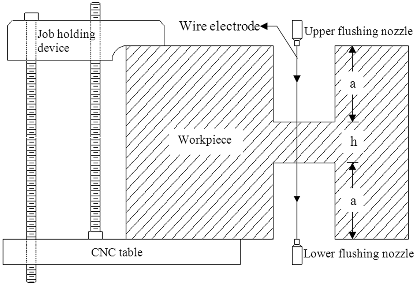
Schematic description for flushing nozzle height ‘a’ and job thickness ‘h’.
Experimentation
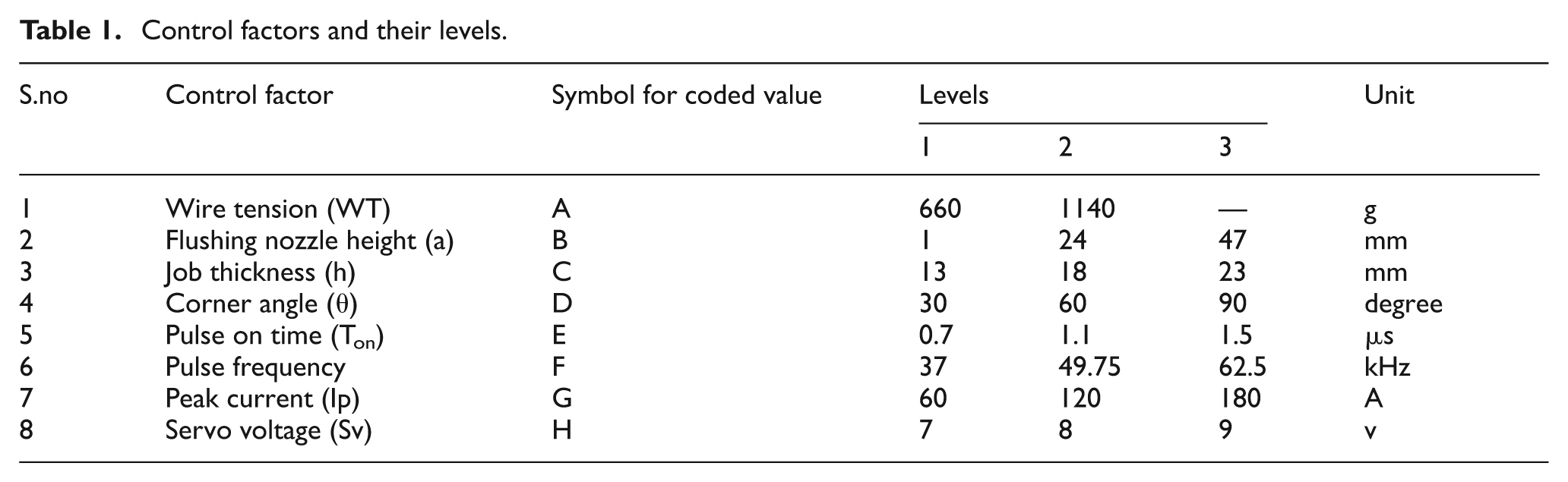
Experiments were conducted according to Taguchi’s L-18 orthogonal array, on an ELECTRA SUPERCUT 734 series wire electrical discharge machine, with Monel 400 alloy as the workpiece (anode) and brass wire of 250 µm diameter as a tool electrode (cathode). The control factors listed in Table 1 have been chosen based on the literature and the trial runs. During trial experiments it is observed that the corner error at the die, measured in terms of uncut corner area (µm2) is more for smaller corner angles. Therefore, a corner angle ranging from 30° to 90° has been considered as a control factor by suitably modifying the cross section of the job, as illustrated in Figure 2. Three different computer numerically controlled (CNC) programs have been created through ELAPT (Electra Automatic Programming Tool) software in accordance with the die corner angle and employed for experimentation.
Control factors and their levels.
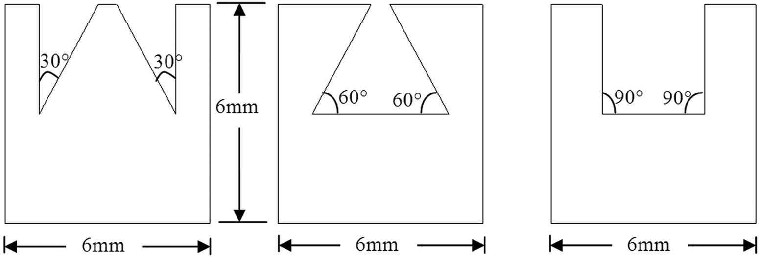
Job profile with corner angles.
Other factors that are anticipated to have a meager effect on the measure of performance are kept constant, i.e. dielectric (distilled water), temperature of the dielectric (26 °C), conductivity of the dielectric (20 mho), dielectric flushing pressure (2.5 kg/cm2), servo feed setting (proportional mode – 0050), peak voltage (100 V), wire feed rate (7 m/min), threshold setting (60%) and angle of cut (vertical). By keeping these factors at a constant level, the effects of the major influencing factors, as shown in Table 1, can be effectively studied with the minimum number of experiments.
The cutting speed data (mm/min) were directly obtained from the monitor of the machine tool generator ELPULS 40. The mrr in mm2/min is computed by multiplying the thickness of the workpiece with the cutting speed. Surface roughness values, were measured using PERTHOMETER, manufactured by Mahr, Germany. The die corner error was measured with the aid of an OLYMPUS make, STM6 model measuring microscope and the dimensional shift was measured using a digital micrometer.
The dimensional shift is defined as half the width of the cut (kerf width), as illustrated in Figure 3, and is the sum of the radius of the wire electrode and the over cut. The over cut can be viewed as the sum of the gap width and the amplitude of wire vibration owing to sparking. The dimension of the finished job is undersized by half the width of the cut. In practice, the dimensional shift is obtained by measuring the dimensions of the finished job. The dimensional shift is half the difference between the programmed dimensions to the actual dimension of the finished product. The dimensional shift has been considered as a response during the modeling of the process. But actually it is a control factor, passed to the CNC system as a wire offset (or wire compensation) value to enhance the dimensional accuracy of the product. All the experiments were conducted with a zero wire offset setting and the dimensional shifts have been measured along with other responses. The summarized experimental results are presented in Table 2.
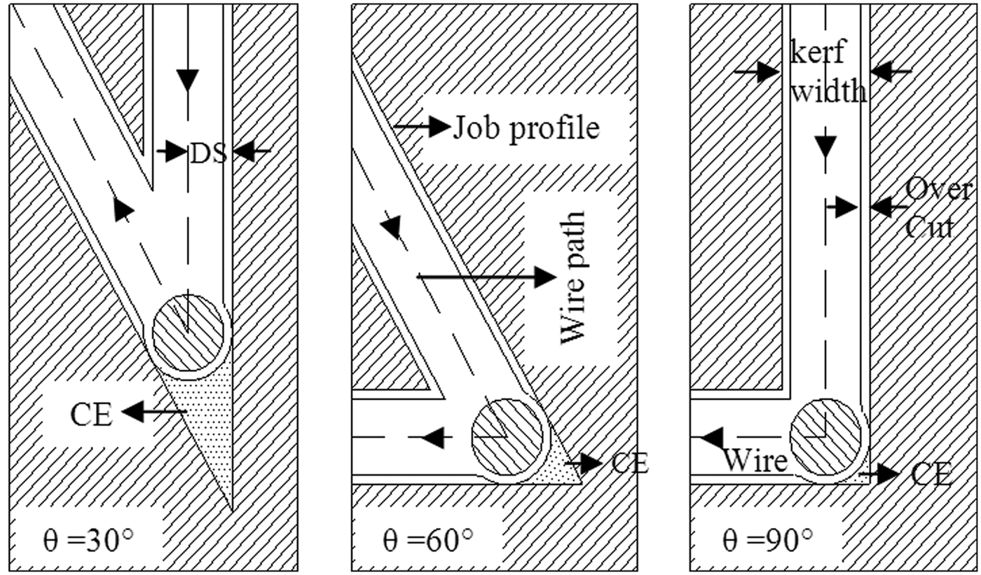
Variation of CE in accordance with corner angle.
Summary of the experimental results.
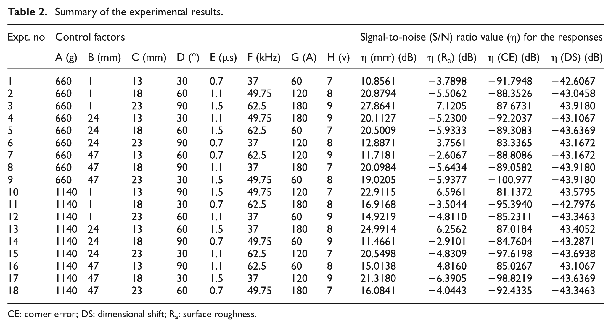
CE: corner error; DS: dimensional shift; Ra: surface roughness.
Additive modeling of WEDM process
Additive modeling has been employed on the basis of matrix experiments using orthogonal arrays. 16 An additive model can be viewed as a superposition model or a variable separable model. It can be noted that a superposition model implies that the total effect of several factors is equal to the sum of individual factor effects. It is possible for the individual factor effects to be linear, quadratic or of higher order. In an additive model, cross product terms involving two or more factors are not considered.
The predicted signal-to-noise (S/N) ratio
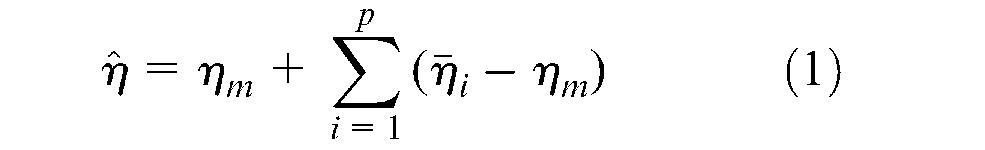
where
Verification experiments along with the prediction error.
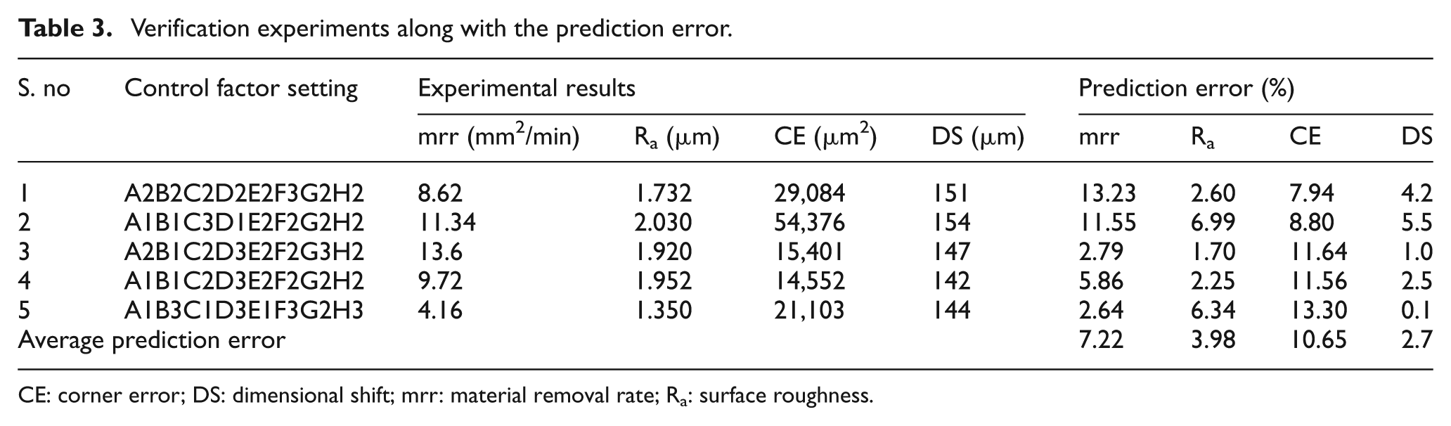
CE: corner error; DS: dimensional shift; mrr: material removal rate; Ra: surface roughness.
The prediction error reported in Table 3 strongly indicates that this model is plausible for prediction.
Parametric analysis through Taguchi methodology
In WEDM, the lower surface roughness (Ra), lower corner error and the higher mrr are the indication of better performance. Therefore, for obtaining optimum machining performance characteristics, “lower is better (LB)” for surface roughness and corner error; “higher is better (HB)” for the mrr, were selected. Analysis of variance (ANOVA) was performed to determine the relative significance of the different factors. Total ANOVA, by considering both machine controllable and uncontrollable factors, and separate ANOVA for machine controllable factors while fixing the uncontrollable factors at level 2 and vice versa, are shown in Tables 4 and 5, respectively.
Total ANOVA.
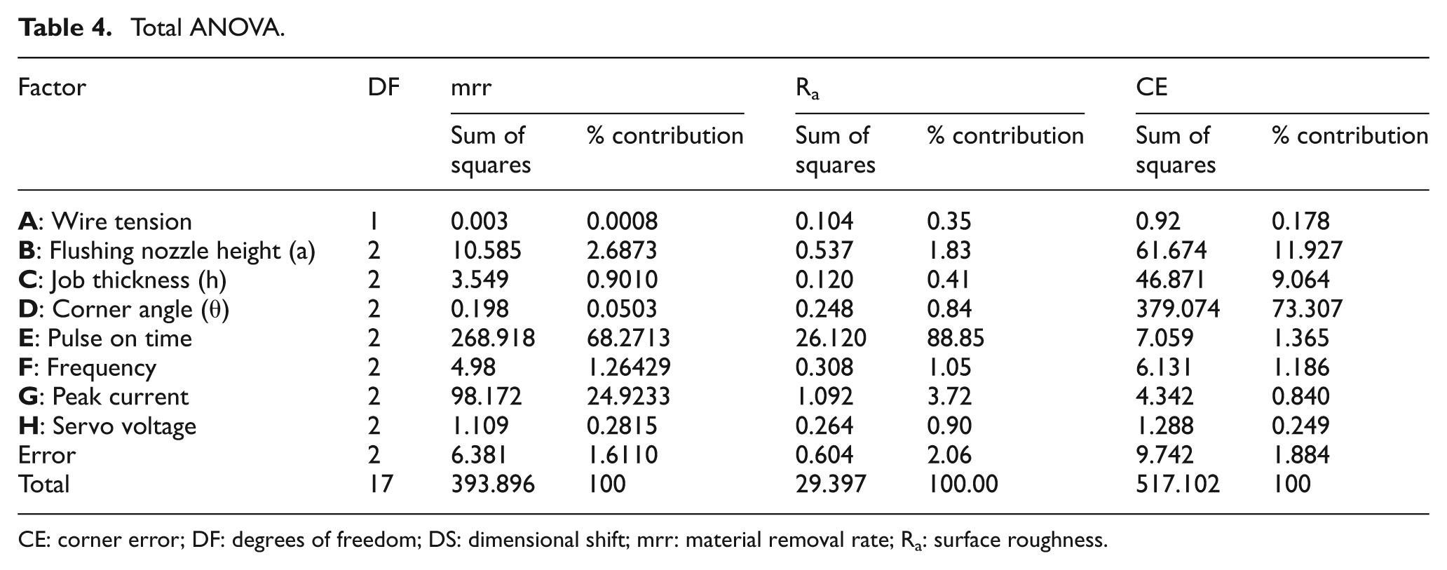
CE: corner error; DF: degrees of freedom; DS: dimensional shift; mrr: material removal rate; Ra: surface roughness.
Separate ANOVA for machine controllable and uncontrollable factors.
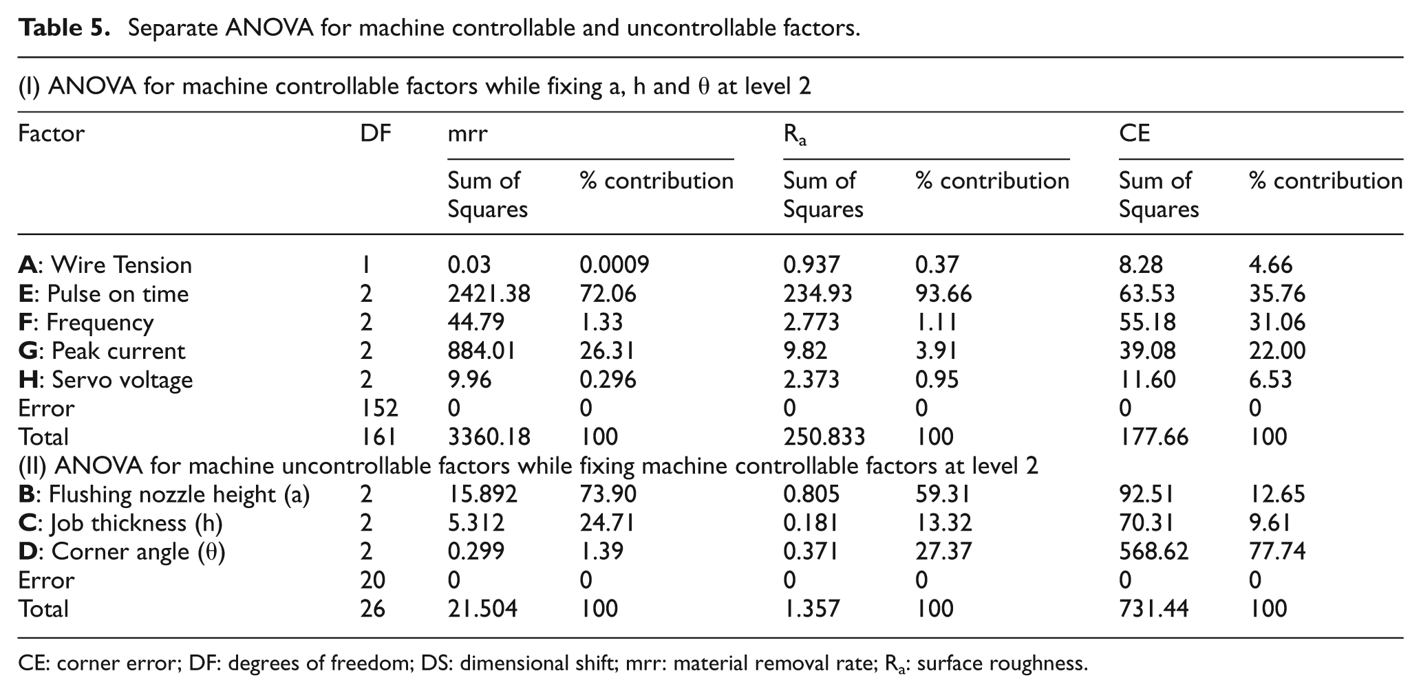
CE: corner error; DF: degrees of freedom; DS: dimensional shift; mrr: material removal rate; Ra: surface roughness.
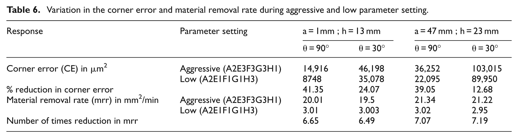
From Table 4, it is observed that the pulse-on time and peak current are the significant factors in determining the mrr and surface roughness. The machine uncontrollable factors, namely corner angle (θ), flushing nozzle height (a) and job thickness (h) are the predominant factors (percentage contribution: 94.3%) in determining the corner error. The machine controllable factors, such as pulse-on time, pulse frequency and peak current are having negligible influence on corner error compared with uncontrollable factors. Therefore, it is obvious that the parameters (machine controllable factors) reduction at the corner will not yield fruitful results in improving corner accuracy, especially during worst working conditions, such as cutting a smaller corner angle on a higher thickness job with higher flushing nozzle height. This is experimentally verified through Table 6. The corner error measurement for aggressive (A2E3F3G3H1) and low (A2E1F1G1H3) parameter settings for flushing nozzle height (a): 47 mm; job thickness (h): 23 mm; corner angle (θ): 30°, is illustrated in Figure 4.
Variation in the corner error and material removal rate during aggressive and low parameter setting.
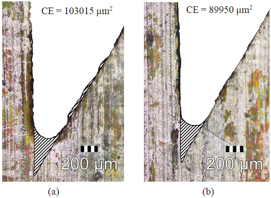
Corner error measurement for aggressive and low parameters setting for a = 47 mm, h = 23 mm and θ = 30°.
From Table 6, it is observed that the percentage reduction in corner error for a = 47 mm, h = 23 mm, θ = 30° is 12.68%, owing to the change of cutting parameters from aggressive to low. Meanwhile the mrr is 7.19 times reduced. It reveals that the cutting parameter modification, from aggressive to low, drastically reduces the mrr, whereas the corner accuracy improvement is meager. Hence, the parameter modification is not an appropriate choice to improve corner accuracy. If a WEDM professional prefers, a parameter modification to improve corner accuracy, as advocated by most of the WEDM manufacturers, is merely wasting time instead of improving corner accuracy. In this circumstance, multi-pass cutting (one rough cut followed by one or more trimming cuts) or a wire path modification at the corner to compensate the wire lag, may yield better corner accuracy.
The dimensional shift is not a true response in determining the productivity of the WEDM process. Thus, the ANOVA test and the factor effects are found to be superfluous. However, the dimensional shift has been predicted and passed to a CNC system as a wire offset value to enhance the dimensional accuracy of the product.
Figure 5 depicts the effect of machine controllable factors on the mrr when fixing uncontrollable factors at a constant level (level 2). Figure 6 illustrates the effects of machine uncontrollable factors on the mrr by keeping machine controllable factors at a constant level (level 2). In a similar fashion, Figures 7 and 8 and Figures 9 and 10 have been plotted for surface roughness and corner error, respectively.
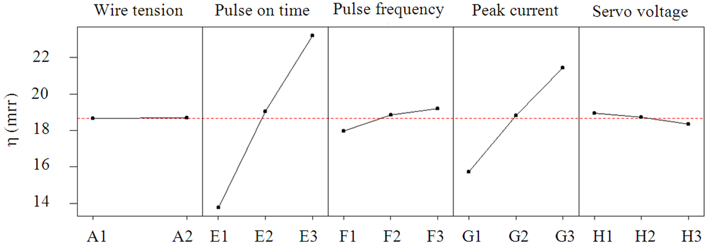
Factors effects for machine controllable factors on the S/N ratio of mrr.
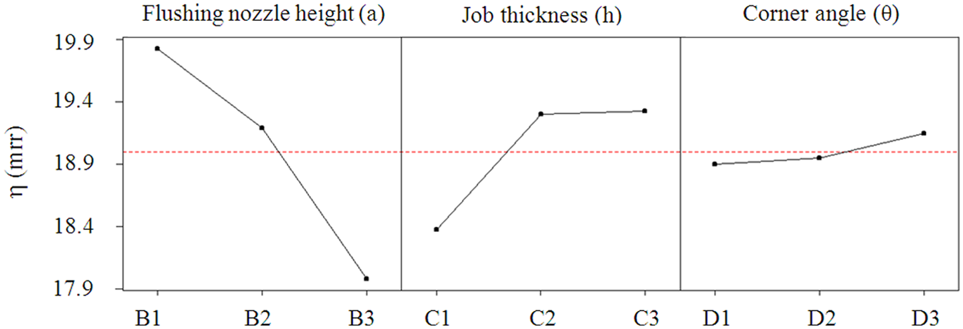
Factors effects for machine uncontrollable factors on S/N ratio of mrr.
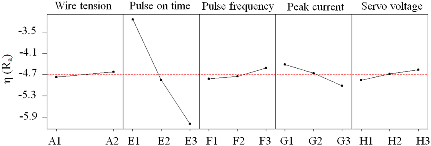
Factors effects for machine controllable factors on S/N ratio of surface roughness (Ra).
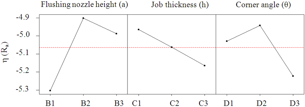
Factors effects for machine uncontrollable factors on S/N ratio of surface roughness (Ra).
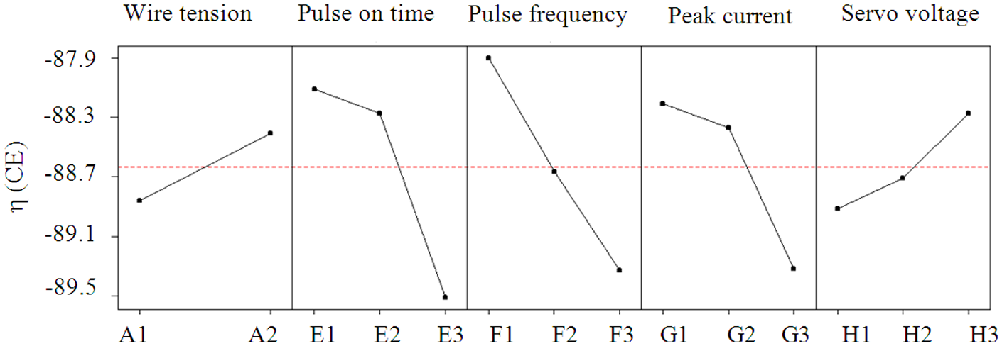
Factors effects for machine controllable factors on S/N ratio of corner error.
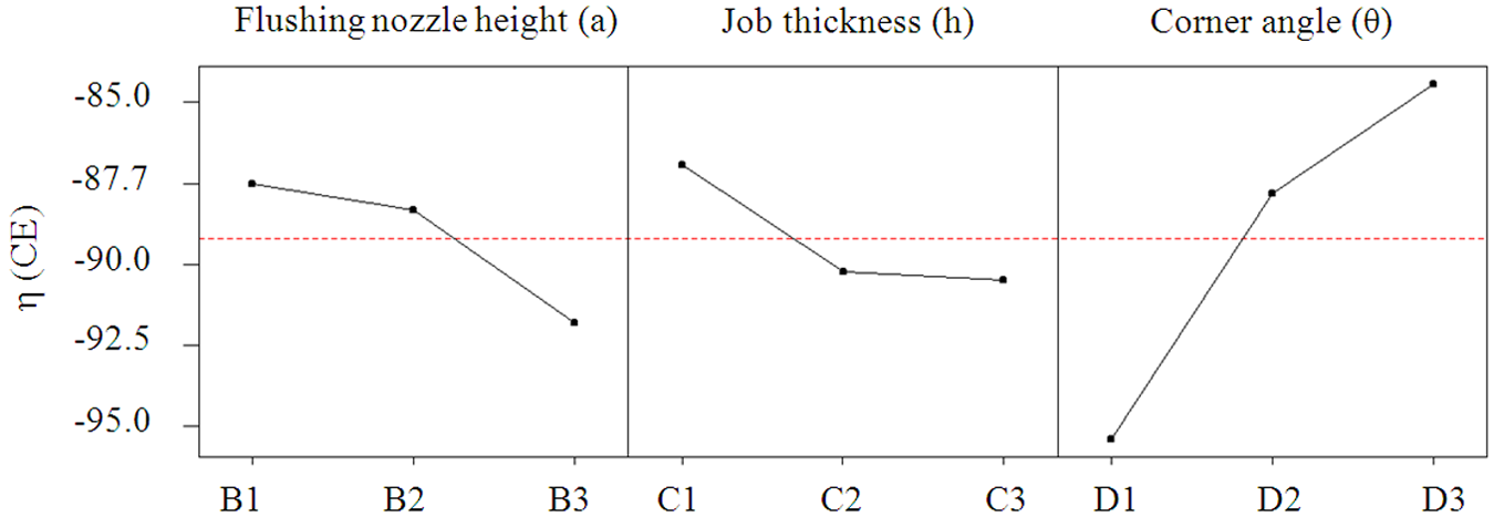
Factors effects for machine uncontrollable factors on S/N ratio of corner error.
The energy content of a single spark discharge is the product of pulse-on time and peak current. An increase in pulse-on time or peak current produces higher energy pulses that can melt and vaporize a higher amount of workpiece material. Therefore, pulse-on time and peak current exhibits an increasing trend with the mrr, as shown in Figure 5. The mrr is almost independent of machine uncontrollable factors, such as flushing nozzle height, job thickness and corner angle. However, from Table 5, it is observed that the flushing nozzle height is the influencing factor among machine uncontrollable factors, which exhibits a decreasing trend with the mrr, as indicated in Figure 6. This is owing to the improper dielectric flushing caused by increasing the flushing nozzle height.
The surface roughness primarily depends upon energy per pulse and the efficiency with which the pulse energy is utilized for creating a crater. The pulse energy utilization efficiency is the ratio between the energy observed by the workpiece to the sum of energy observed by the workpiece and the dielectric medium. The higher energy pulses generated owing to an increase in pulse-on time or peak current produces a greater depth of crater and overcut. Therefore, an increase in pulse-on time or peak current deteriorates the surface finish quality (Ra increases) as illustrated in Figure 7.
From Figure 10, it is observed that the corner accuracy decreases (i.e. corner error increases) with the increase of the flushing nozzle height (‘a’) and job thickness (h), whereas it increases with the increase of corner angle (θ). An increase in the flushing nozzle height (‘a’) produces a higher wire vibration and wire lag. They are the prime causes for corner error. Therefore, an increase in flushing nozzle height, increases the corner error. An increase in job thickness increases the wire span and, hence, the wire lag. This increase in wire lag, promotes the corner error as shown in Figure 10. During ideal conditions (rigid wire with neglecting wire lag, wire vibration and sparking forces), the increase in corner angle diminishes the corner error owing to geometrical constraints. This is visibly shown in Figure 3 and hatched with dots beneath the wire electrode.
Careful examination of Figures 5–10 reveals that the best level of significant factors for mrr, surface roughness and corner error are B1E3G3, E1G1H3 and A2B1D3E1G1, respectively. From this, it is confirmed that the level of significant parameter setting for the mrr, surface roughness and corner error are completely contradictory. Therefore, there is no single parameter setting that could be the optimal choice for all the responses. Hence, there is a requirement to explore a suitable strategy for optimization of this process.
Multi-response optimization of WEDM process
From the previous discussions, it is proved that the corner error is almost independent of machine controllable factors and predominantly influenced by the uncontrollable factors. The percentage of the corner error reduction, observed in Table 6 for higher corner angle (90°), is appreciable owing to parameter reductions at the corner. Therefore, parametric optimization can be performed and the outcome of the optimization can be used to minimize the corner error when cutting higher corner angles. The machine uncontrollable factors, viz. job thickness, flushing nozzle height and corner angle, are decided by the customers and are dependent on product size and shape. So, it is necessary to group machining combinations according to the flushing nozzle height (a), workpiece thickness (h) and the corner angle (θ).
Figures 5, 7 and 9 reveal that the optimal setting for wire tension is level 2 for all the process criteria yields. Therefore, wire tension is considered as a constant factor and kept at the magnitude of 1140 g. The remaining seven control factors can produce 2187 (37 = 2187) machining combinations. This machining combination has been grouped according to flushing nozzle height, job thickness and the corner angle.
Each group has been concurrently optimized using the Pareto optimality approach. The solutions obtained through this approach are non-dominated with respect to one another. In other words, the optimum point is graphically located with respect to its coordinates on mrr (x-axis), surface roughness (y-axis) and corner error (z-axis) axis. The optimum points will have a higher coordinate value in the x-axis and lower coordinate values in the y- and z-axis with respect to other (non-optimal) points. If any two optimal points have the same coordinate value, both will be considered as an optimal point.
The Pareto optimal points for flushing nozzle height at level 2, i.e. a = 24 mm, workpiece thickness (h) 18 mm and the corner angle 60°, are graphed in Figure 11 and visibly marked by filled circles. There are 66 optimal points. Among these, 20 optimal points (taken at regular intervals of corner error for θ = 90°) have been reported in Table 7 as an optimal technology guideline. The pulse frequency is jointly constituted by the pulse-on time and pulse-off time. The pulse-off time is the machine controllable factor that can be directly passed to the WEDM system. Hence, the pulse-off time appeared in Table 7, instead of pulse frequency for ready reference. Similar technology guideline tables for other machining conditions, namely B1C1, B1C2, B1C3, B2C1, B2C3, B3C1, B3C2, and B3C3, can be produced. Table 7 can be used as a handy technology guideline for optimal machining of Monel 400 alloy of 18 mm thickness with the flushing nozzle height a = 24 mm as briefed below.
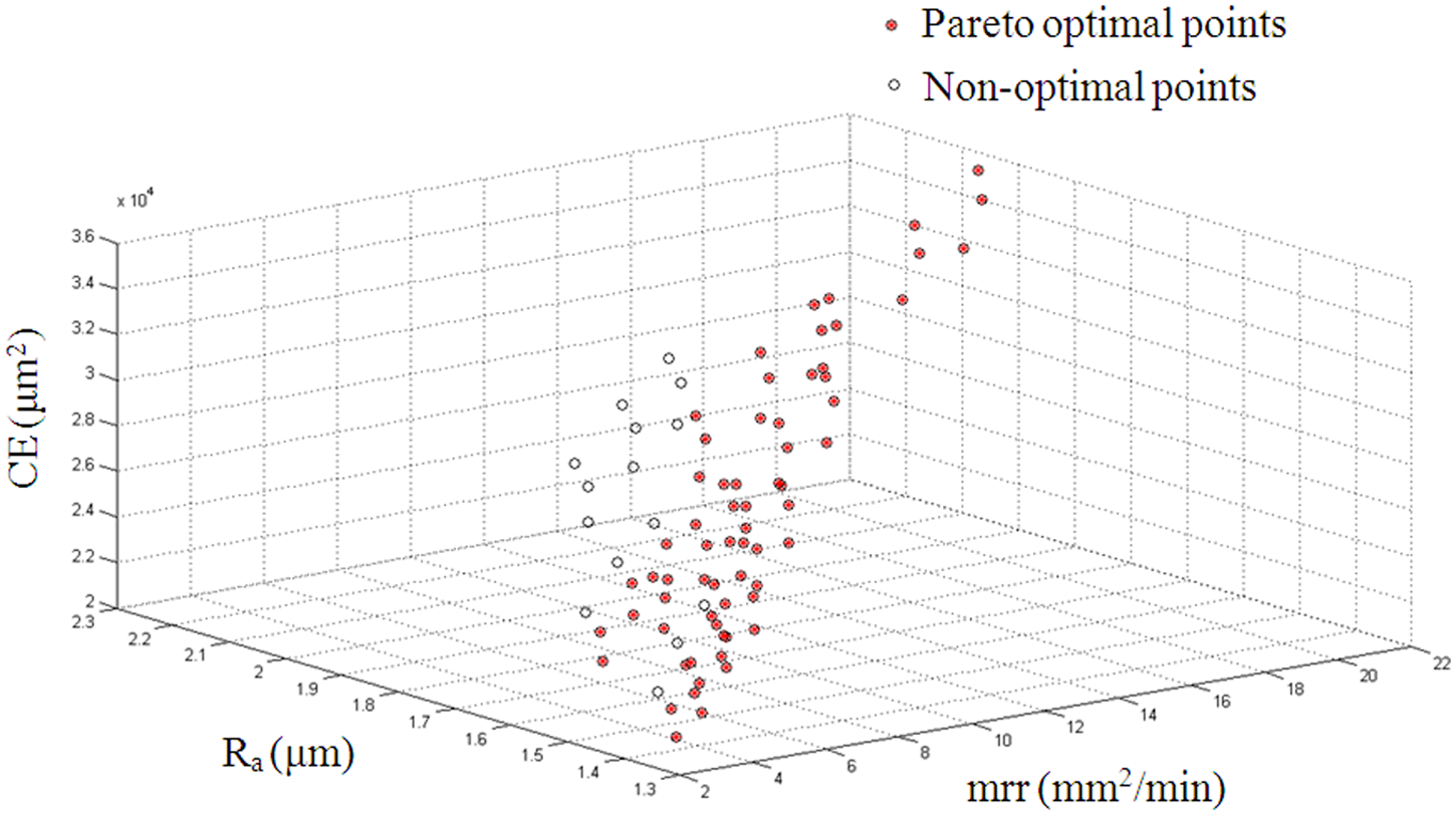
Graphical display for Pareto-optimal points for a = 24 mm, h = 18 mm and θ = 60°.
Technology guideline for job thickness 18 mm with ‘a’ = 24 mm.
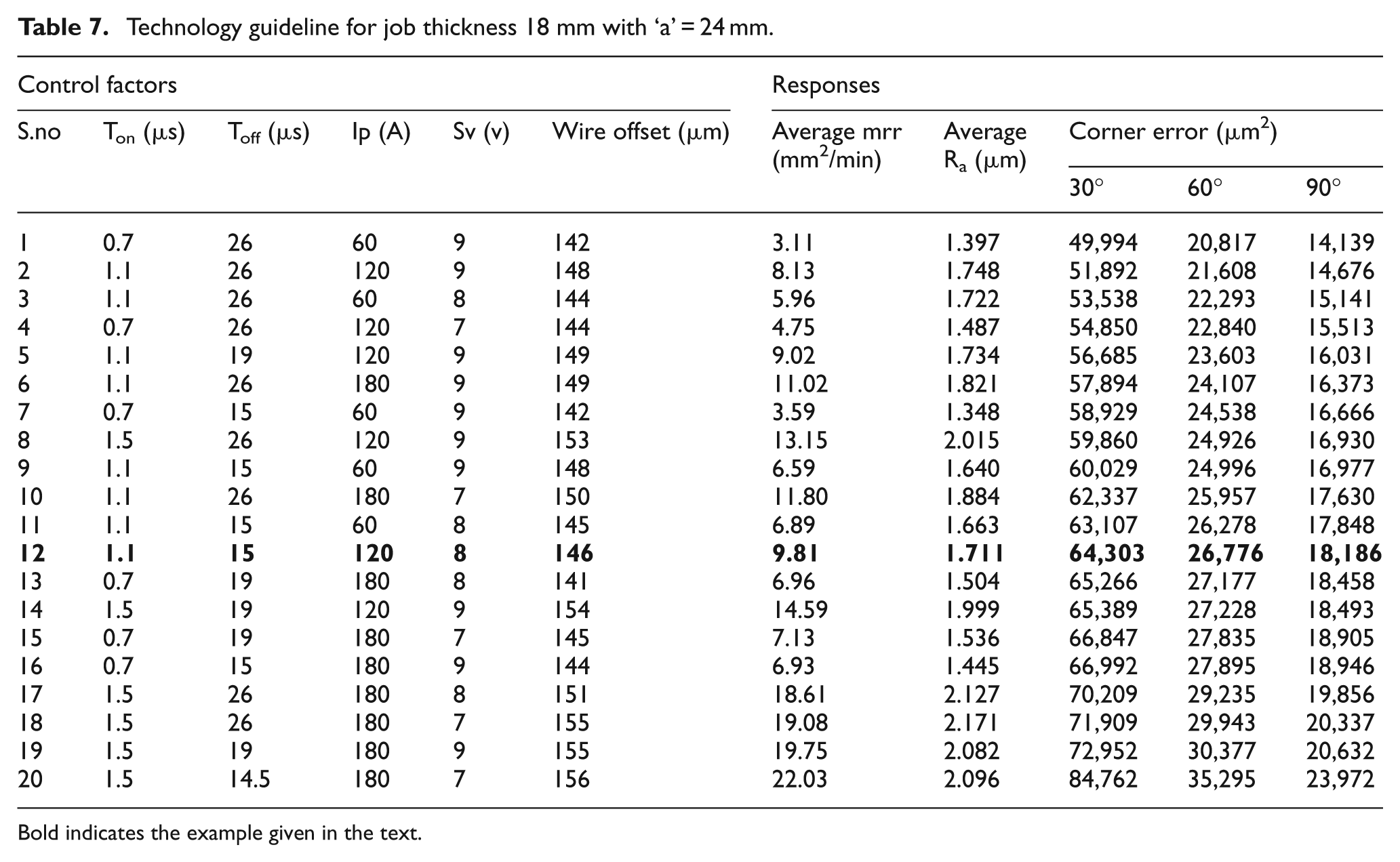
Bold indicates the example given in the text.
For instance, a customer demands a component with Ra ≤ 1.8 µm and corner error ≤ 19,000 µm2 for 90°. The optimal parameter setting for this circumstance can be selected from Table 7 (S.no. 12, in bold) as a pulse-on time of 1.1 µs, pulse-off time of 15 µs, peak current of 120 Å and servo voltage of 8 v yields the mrr of 9.81 mm2/min, surface roughness of 1.711 µm and corner error of 18,186 µm2. The obtained dimensional shift (wire offset), 146 µm, is incorporated in the CNC part program to enhance the dimensional accuracy of the machined part.
Conclusion
In the present research article, die corner accuracy during WEDM of Monel 400 alloy has been reported. The control parameters were categorized as machine controllable factors (sparking factors, such as pulse-on time, peak current, etc.) and uncontrollable factors, and their influence on the responses were studied using Taguchi methodology. The mrr and surface roughness were predominantly influenced by the pulse-on time and peak current. The corner accuracy was almost independent of sparking factors and is chiefly influenced by uncontrollable factors, namely flushing nozzle height, job height and corner angles. The impact of the pulse parameters modification in corner accuracy improvement has been analyzed. Later, the machining combinations were grouped according to the uncontrollable factors and optimized using a Pareto optimization technique. A sample technology table, for job thickness 18 mm and flushing nozzle height 24 mm, has been reported with its industrial usage.
The striking outcome of this experimental result proved that the cutting parameter modification strategy yields poor results in improving corner accuracy during the presence of huge wire lag caused by higher job thickness and the elevated flushing nozzle height. To obtain better corner accuracy, the other strategies, such as multi-pass cutting or wire path modification at the corner, are proposed. The future scope of this work will include the multi-pass cutting to minimize corner error and to improve surface characteristics along with productivity.
Footnotes
Acknowledgements
The corresponding author gratefully acknowledges the management of National Engineering College, K.R.Nagar-628 503, Tamilnadu, India, for deputing him to pursue research under the QIP scheme of AICTE, New Delhi.
Funding
This research received no specific grant from any funding agency in the public, commercial, or not-for-profit sectors.