
Abstract
Welding distortions cause problems in assembly and performance of weldments, including nozzles in pressure vessels. In the present work, a three-dimensional thermo-mechanical finite element model was expanded to study the effect of the welding sequence on welding distortions in a pressurized nozzle. Among different types of distortions, shrinkage and angular distortions have been investigated. Since changes in the welding sequence increase the computational time and complicate the welding process, the effects of the welding sequence in different passes have also been studied. For the case studies, a five-pass shielded metal arc welding with V-joint geometry has been selected. The vessel has a diameter of 2000 mm and a thickness of 8 mm, and the nozzle has a diameter of 100 mm and a thickness of 8 mm. The pressure vessel and nozzles are made of 304 stainless steel material with the same chemical compositions. The finite element and experimental results have been compared, and turned out to be in good agreement. The results showed that welding in four sections with a proper sequence has significant influence on decreasing angular distortions, but the welding sequence is not an effective parameter to reduce the shrinkage type distortions. Moreover, sequencing can be used in some passes to simplify the welding process and also to decrease the process time.
Introduction
Metallurgical welding joints are extensively used in the fabrication industry, including ships, offshore structures, steel bridges and pressure vessels. Among the merits of such welded structures, high joint efficiency, water and air tightness, and low fabrication cost can be counted. However, residual stresses and distortions can occur in the structure owing to localized heating by the welding process and subsequent rapid cooling. 1 Pressure vessels are one of the most commonly used structures that are mainly constructed by welding. During the welding of a nozzle to a pressure vessel, in view of localized and asymmetric heating, distortions occur and cause problems, particularly during the assembly process of the vessel. These distortions occur in different shapes, but shrinkage and angular distortions may be the most significant types in nozzles. In order to decrease welding distortions in nozzles, it is important to accurately predict them. In this regard, the finite element method (FEM) may be a good choice. Recently, some researchers have developed three-dimensional (3D) models to simulate welding, considering detailed welding conditions, but their models focused on residual stresses and different ways to minimize them.1–3 There are some other published researches that have developed finite element (FE) models to predict and decrease welding distortions, but in these works, the studied geometries are either simple or other types of distortions have been investigated.4–7
In the present work, both experimental and numerical investigations are incorporated to study welding shrinkage and angular distortions in nozzles and decrease them through the introduction of a proper welding sequence.
An ABAQUS software package was employed to conduct the thermo-mechanical FE analyses, and a section of the vessel was simulated to decrease the analysis time.
Theoretical aspects
Welding distortions are calculated here taking advantage of the FE method. Similar published works have explained theoretical aspects of welding phenomena extensively,8–11 so in this article they are briefly described.
Thermal analysis
When a volume is surrounded by an optional surface, the heat flow balance is expressed by

where


where
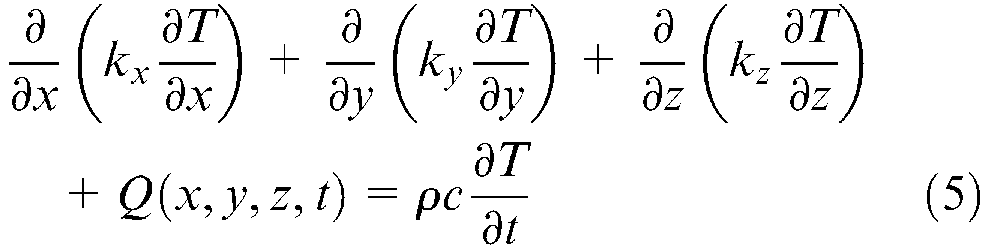
Equation (5) is the main differential equation that explains the thermal part of the phenomena. By applying the initial and boundary conditions described inSattari-Far and Farahani 10 and Akbari and Sattari-Far, 11 general solution of the problem is obtained, which gives temperature distribution in the body.
Mechanical analysis
Equilibrium and elastic–plastic constitutive equations are expressed by equations (6) and (7) respectively


where
Using the full Newton–Raphson method to obtain the incremental stress is explained in Chang and Teng. 12
FE modeling
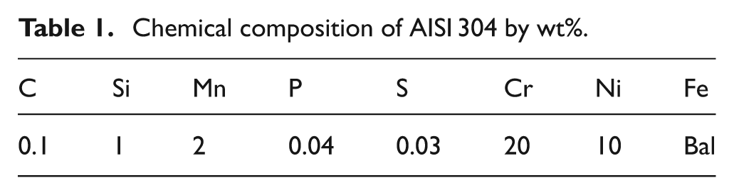
In this study, the welding process has been simulated taking advantage of the FE method using ABAQUS software package. Input files in corporation with user subroutines of DFLUX and FILM were employed to mathematically model the welding process. 13 Uncoupled thermal-mechanical analyses were conducted to simulate the thermo-mechanical phenomena during the welding process. It is to mean that the temperature fields are first determined through a solution of heat transfer equations, regardless of contribution of the negligible thermal work, occurred through expansion, to the heat loss. Subsequently, mechanical analyses were performed to calculate stresses and displacements, by incorporation of the thermal analysis results as thermal load and introduction of thermal expansion coefficient. The material used in this study is AISI type 304 stainless steel, with a chemical composition as given in Table 1 and yield strength of about 300 MPa. Other mechanical and thermo-physical properties of AISI 304 are described in Deng and Murakawa. 14
Chemical composition of AISI 304 by wt%.
In the thermal analysis phase, 3D FE models were provided incorporating 12,000 eight-noded brick elements of type DC3D8 (containing thermal degrees of freedom), after study of the mesh size effect. A schematic view of FE model is shown in Figure 1.
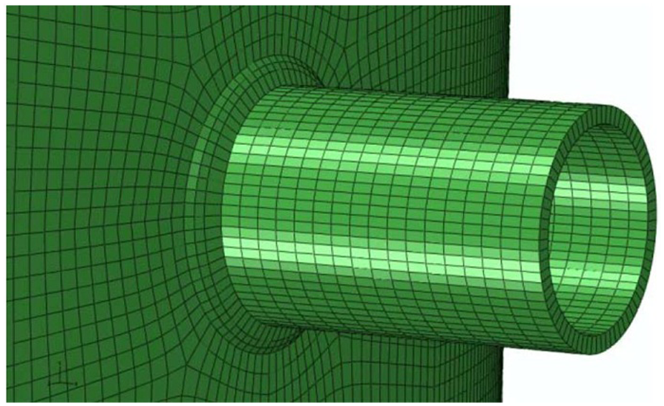
Schematic view of the FE model.
The element birth technique was employed throughout thermal analysis to model weld metal deposition during welding. Five passes were modeled according to the sequences depicted in Figure 2.
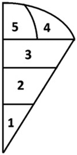
Sequence of passes in welding of the nozzle.
The heat source has been modeled through evenly distributed flux throughout the weld elements using the DFLUX user subroutine in ABAQUS. The heat flux was calculated making use of the following equation

where
For thermal boundary conditions, convection and radiation are the phenomena to be considered. Radiation is dominant for higher temperatures, while convection accounts for the majority of the heat loss in lower temperatures. Nevertheless, it is quite customary to consider a combined convection coefficient that includes radiation effects in higher temperatures, in order to avoid the complexities associated with radiation modeling. Herein, the combined convection coefficient model (proposed by Brickstad and Josefson 15 ) has been widely used by different researchers. Accordingly, this model has been employed in this work taking advantage of the FILM user-subroutine.
In the mechanical analysis, the thermal analysis results (temperature histories) were applied to the model as thermal loads. The FE model here is the same as that of the thermal analysis, except for the element type, which is C3D8 (8-noded brick element), in order to obtain stress fields and distortions. Likewise, MODEL CHANGE keyword was utilized in the code to model weld metal deposition during welding, which is essential to attain correct distortions. For mechanical boundary conditions, four nodes of the vessel were assumed fixed to prevent the part’s movement. Before the main welding, nozzle was welded to the vessel by two tack welds, so, elements that were in the tack weld’s locations were not removed in mechanical analysis to act like the vessel’s body. Here, the plastic properties of the material were included through the application of an isotropic perfect plastic model.
Experimental investigations
Determination of proper dimensions for the experimental test
In this project, the goal was to minimize the distortions associated with a relatively large vessel (Figure 3) with the dimensions provided in Table 2. This vessel was made of rolled plates that were welded in horizontal and vertical directions. After manufacturing the vessel’s shell, some holes were created to install the nozzles and then these holes were beveled by a manual grinding machine to make a V-joint geometry. Nozzles were cut from a tube with the same material as the vessel, and finally were welded to the shell by shielded metal arc welding. In view of the limitations attributed to financial and material shortages, it was not available for the researches to perform experiments on a real size vessel. Accordingly, a study was carried out in order to find the proper dimensions so as to obtain results with the least corresponding errors. In this regard, studies on the height and the section angle of the sample were performed, and finally the proper dimensions were extracted.
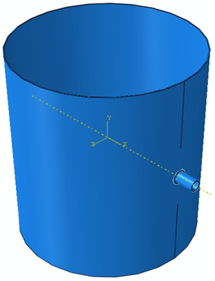
Schematic model of the vessel and it’s nozzle.
Vessel and nozzle’s dimensions.
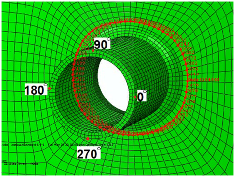
In order to obtain the proper height, parts with heights of 2000, 1000, 700 and 500 mm were modeled. These values were selected according to the availability of test materials. The extracted height must not have imposed errors between the results attained through modeling the full size vessel and the small modeled section, beyond an acceptable limit.
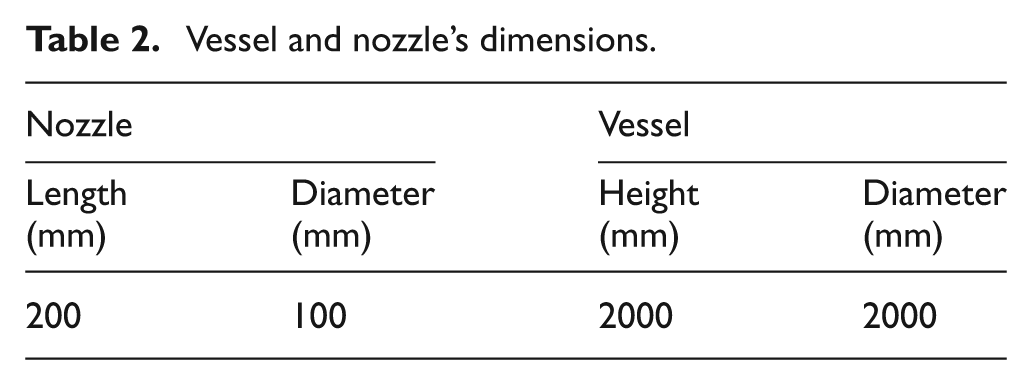
The shrinkage results demonstrate the linear distortions of the nodes on a path 5 mm distant from the weld edge, as illustrated in Figure 4. The nozzle shrinkage results for the four models were depicted in Figure 5. In the latter diagram, the points on the path are presented through their angular distance from the welding start point (0° in Figure 4).
The path 5 mm distant from the weld edge.
The shrinkage distortions in models with different heights.
To examine angular distortions, two points named point 1 and 2 have been considered. Point 1 represents the point on the nozzle tip corresponding to the welding starting point (0° in Figure 4), and point 2 refers to the point on the nozzle tip angularly distanced 270° from point 1. The angular distortions of point 1 in the x direction and point 2 in the y direction have been calculated. Table 3 presents the results of angular distortions as an outcome of angular distortions in x and y directions. In fact, this table represents nozzle’s axis angular distortions.
The angular distortions in models with different heights.
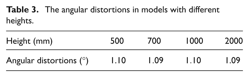
Table 3 shows that changes in model’s height do not affect angular distortions. In view of the attained results (Figure 5 and Table 3), the 700 mm model, while imposing small costs and being available, brings around 10% error in the results, which is in an acceptable range. Therefore, 700 mm was selected as the height of the vessel sample.
The same procedure as above was also carried out in order to come by the proper section angle for the testing sample. In this regard, models with angles of 90°, 45° and 30° were provided alongside the original 360° model (Figure 6). Likewise, shrinkage and angular distortions of the nozzle were studied in this part for the path and points discussed previously.
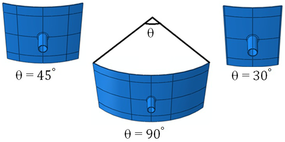
Models with angles of 90°, 45° and 30°.
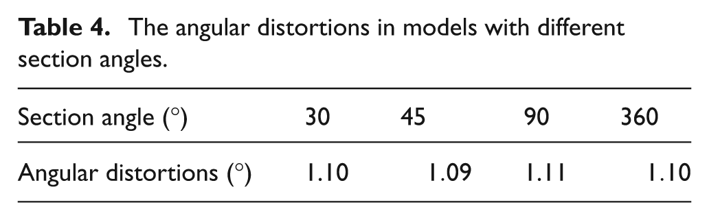
Figure 7 and Table 4 illustrate the results associated with shrinkage and angular distortions of the nozzle. As inferred from the latter figure and table, all of the models have the same behavior, but the 45° section imposes less than 10% in the results; hence selected for experimental studies. Nevertheless, as rolling of a 45° plate confronted problem and in view of the fact that two similar plates were required for the project (for initial model validation and final verification), two 45° samples were provided in a single 90° section in the experimental work. In order to make sure that this double 45° section specimen bore the same results as a single 45° one, it was modeled, as presented in Figure 8, with the results compared with those of a single 45° section. The simulation results revealed that the maximum difference was less than 3%, and provided the confidence for further simulations.
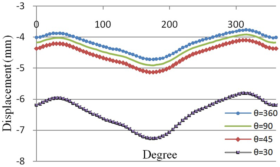
The shrinkage distortions in models with different section angles.
The angular distortions in models with different section angles.
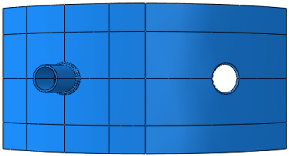
A single 90° section applied in the experimental work.
Verification of welding model
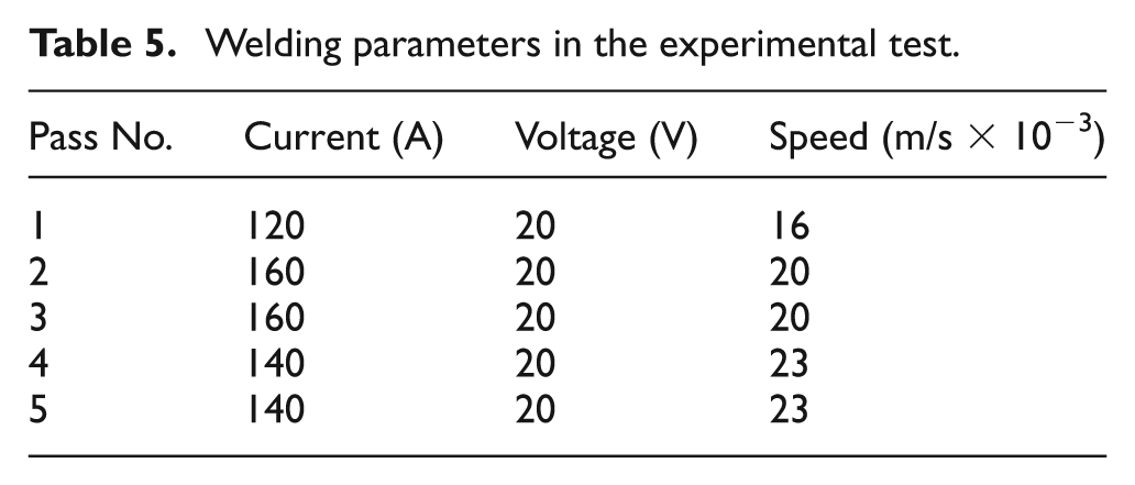
After finding the proper dimensions, an experimental test was performed using an E 308-16 electrode with 2.4 mm diameter. Direct current, with reverse polarity and no sequencing technique were applied during welding, other welding parameters are described in Table 5.
Welding parameters in the experimental test.
The shrinkage and angular distortions were measured twice, before and after welding, and their differences were calculated as welding distortions. Figure 9 shows the experimental measurement in this project.
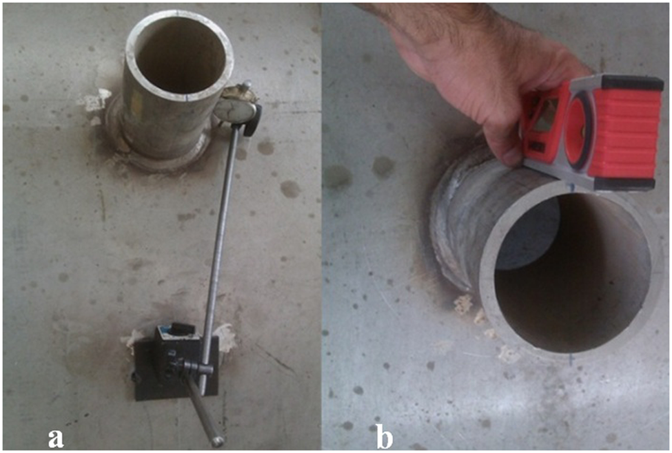
The experimental measurements: (a) measuring shrinkage distortions; (b) measuring angular distortions.
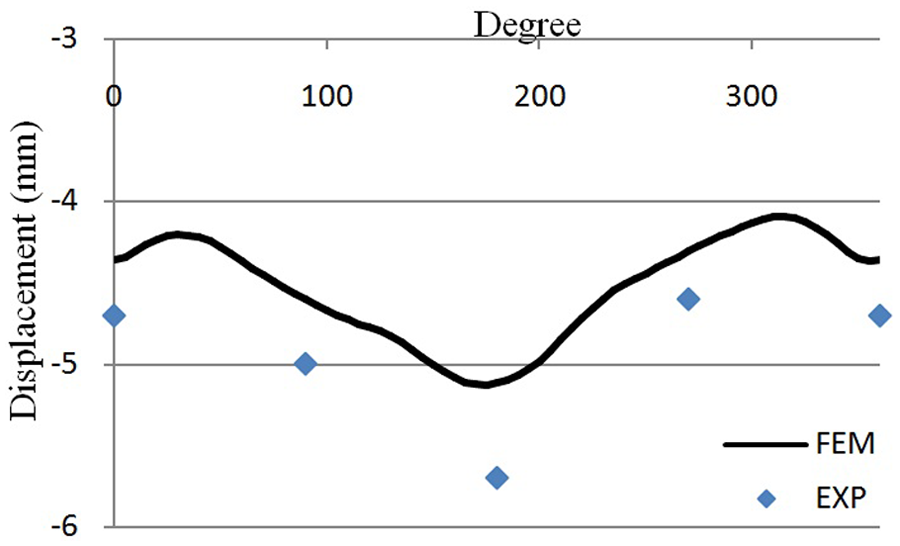
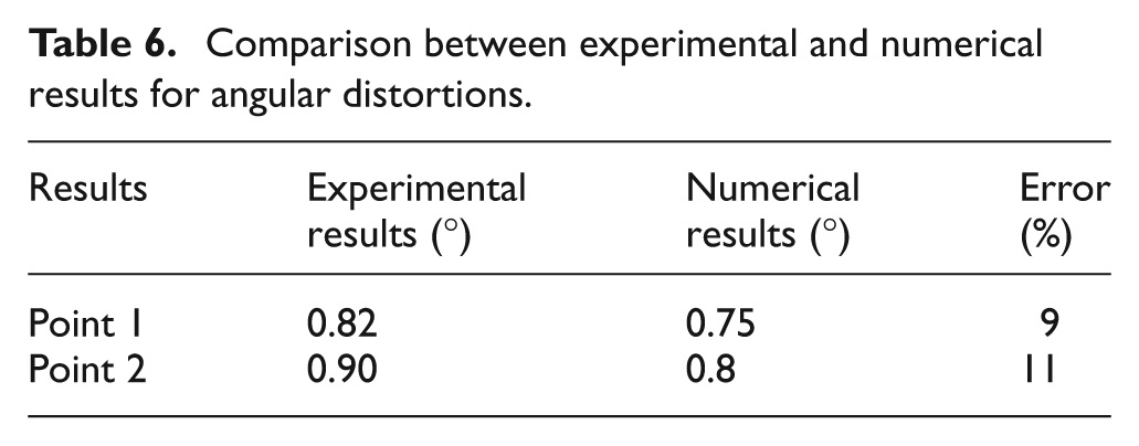
The same processes were modeled by the FE method, and their results were compared with the experimental measurements in Figure 10 and Table 6. They show good agreement between the FE results and experimental measurements, having a deviation of around 10%, and it shows the capability of the FE model to predict distortions in the nozzle welded with different sequences.
Comparison between experimental and numerical results for shrinkage distortions.
Comparison between experimental and numerical results for angular distortions.
Results and discussion
Finding the proper sequence
There are different welding sequences that can be used to decrease distortions; for example welding in two, four or eight sections. Welding nozzles in two sections of 180° is the most common sequence in industry, but four-section sequences are used to create maximum symmetry in temperatures, and are effective in decreasing distortions. Welding nozzles in six or eight sections can be more helpful in decreasing distortions, but as they are time-consuming and costly, they are not common sequences in industry. A total of five different sequences were examined in welding the discussed nozzle, as shown in Figure 11. The case a, in which welding is performed entirely in one section from the starting to the final point, was chosen as the basic case here. This case was used in the experimental investigations as discussed before. All the five sequences were analyzed by FE modeling to calculate the distribution of shrinkage distortions and the maximum angular distortions.
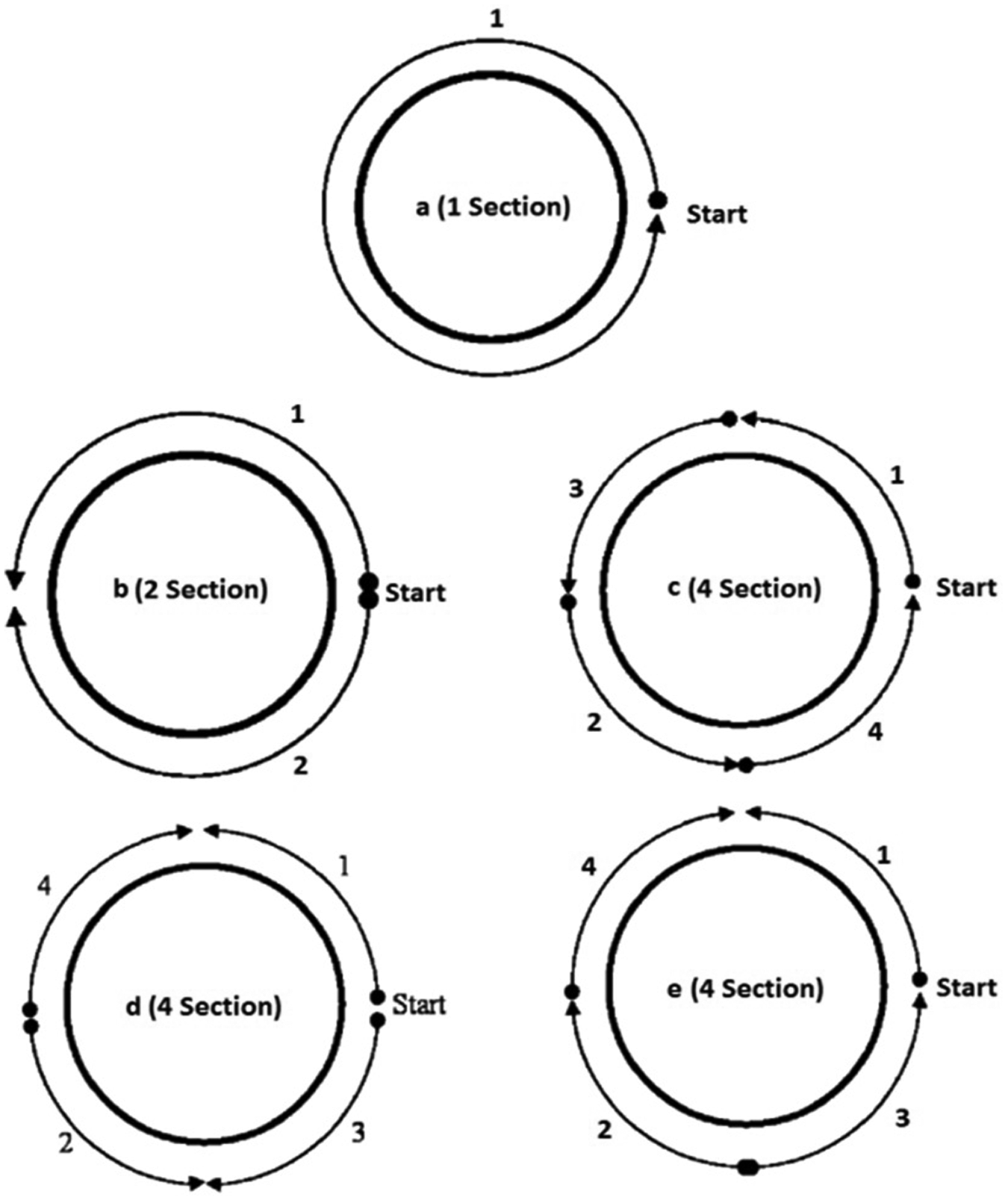
Five sequences for nozzle welding, investigated in this study.
Figure 12 illustrates the comparison between the shrinkage distortions attributed to all the five sequences. This figure shows that the welding sequence does not affect shrinkage distortions remarkably, but in cases c and d, shrinkage distortions are less than the other sequences. Applying sequencing in this case decreases shrinkage distortions around 5%.
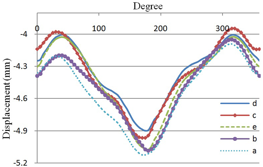
Comparison between the five sequences; shrinkage distortion results.
Figure 13 displays a comparison of the maximum angular distortions (as an outcome of angular distortions in x and y directions) in all the five cases. This figure shows that through increasing welding sections, welding distortions are decreased. In cases c, d and e, welding is conducted in four sections, but in different sequences. The results reveal that minimum distortions occurred in case c, which is lower than case a (without sequence), over 20%.
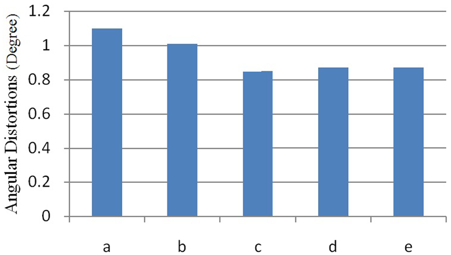
Comparison between the five sequences; angular distortion results.
Influence of welding sequences in different passes
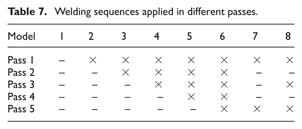
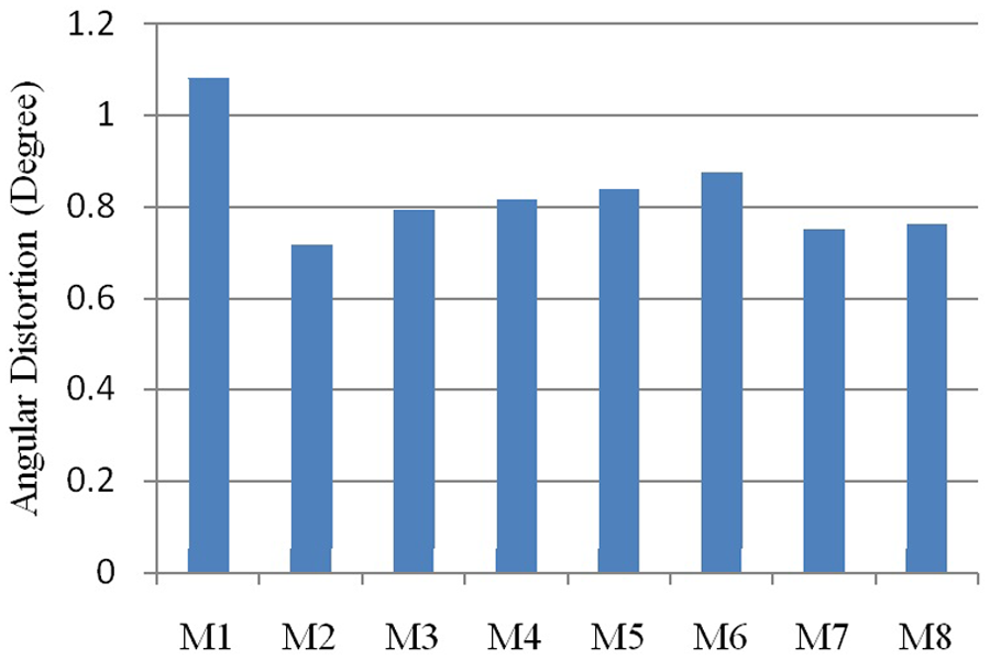
Since applying various welding sequences in different passes may increase the welding time, the effect of welding sequences in different passes was studied. In order to study this subject, an FE model with five passes was prepared and different combinations of case a and c were analyzed as presented in Table 7. In this table, the passes in which sequence c was applied are shown by × mark and passes in which case a was implemented are shown by – mark. Maximum angular distortions of all the eight models are depicted in Figure 14.
Welding sequences applied in different passes.
Five sequences for nozzle welding investigated in this study.
Figure 14 reveals that model 2 is the best combination of sequences to achieve the least distortions. In this model, welding sequence c was only applied in the first pass, and for the other four passes, no welding sequence was implemented. The results show that to achieve the least angular distortions in a nozzle, it is not necessary to apply a welding sequence in all of the passes. The angular distortion of model 2 is around 35% lower than model 1 (without applying sequencing), which is a remarkable value.
Conclusions
In this article, a 3D FE model was developed to predict shrinkage and angular welding distortions in penetration nozzles. In view of the attained results, the 700 mm model with a section angle of 45°, while imposing small costs and being available, brings less than 10% error in the results, which is in an acceptable range. Comparing experimental results with FE results showed that the used computational method was a very effective way to estimate welding distortions. After verification of the FE model, the investigations were focused on welding sequences and their effect on distortions. Based on the studies, the following conclusions were drawn.
Finding a proper welding sequence is one of the most effective methods to decrease angular distortions in penetration nozzles.
Welding a nozzle in four sections can decrease angular distortions over 20%, and with regard to manufacturing costs, this fact can be an applicable sequence in industry.
Application of different welding sequences is not an effective parameter to decrease shrinkage distortions in penetration nozzles.
The effect of welding sequences on angular welding distortions is more obvious in the first pass of weldments.
Footnotes
Funding
This research received no specific grant from any funding agency in the public, commercial, or not-for-profit sectors.