
Abstract
This paper presents an application of an axiomatic design theory-based analytical approach to autobody components assembly in the sustainable manufacturing context. The adjoining edges of autobody and closure steel sheet panels are machined via a computer-controlled laser cutting process. Following the hierarchies of the bill of materials designed in the CATIA V5 environment, the autobody components are assembled manually using the novel τ-stoss technology. The preliminary data obtained from the comparative analysis of the reported LS-DYNA crash simulation of 2 and 3 mm thick τ-stoss technology-based steel front rails shows that a high number of τ-stoss technology-based secondary beams present a preventive material failure at the integration joints. A series of experimental test drives of the τ-stoss technology assembled automobile validated the robustness of the design system and reliability of the τ-stoss technology.
Keywords
Introduction
In today’s global sustainable manufacturing environment, there are myriad manufacturing complexities that significantly affect the design system for low-cost automotive body assembly.1–8 This work presents axiomatic design theory as an applied tool in adjoining the surfaces of autobody and closure components cost-effectively via the novel τ-stoss technology. A design system should satisfy the following two axioms:9–12
the independence axiom (maintain the independence of the functional requirements);
the information axiom (minimise the information content in a design).
The core objectives of the work were set as follows.
To prevent a violation of the independence axiom by eliminating any agents of coupled design, often resulting from a design system in which the functional requirements (nFR) outnumber the design parameters (nDP).
To prevent the high cost-based redundant design system that results from the nDP largely exceeding the nFR.
To achieve an ideal or robust design system by maintaining the information axiom. A robust design ideally takes into consideration the factors and metrics of quality production at low cost within the sustainable manufacturing domain. 13
Applying the axiomatic design theory model
Axiomatic design of a fixed autobody assembly system for identical parts
The objective of achieving an ideal or robust design system for autobody components assembly is basically to reduce variation in the nFR of a system in order to meet customer satisfaction requirements. 13 Maintaining the independence of nFR as well as preventing high manufacturing information content in a design system is practical for identical component parts, an ideal premise to enable reduction in conceptual vulnerabilities. 12 The axiomatic design processes for machining and manually assembling identical autobody component parts are illustrated in the next section.
Axiomatic design equations for τ-stoss autobody assembly
In order to map out the design hierarchy in terms of the high-level minimum set of nFR needed to achieve the desired design, the functional process for assembling the τ-stoss technology-based autobody components into a vehicle requires the manual connection of one component steel sheet’s edges of τ-flaps into respective slits of another of identical material grade. 14 Using a pair of pliers, the τ-flaps in the slits are then slightly twisted to create a temporary interlock at the adjoining surfaces. Once the assemblage exhibits no warping, the twisted τ-flaps are broken off and spot welds are applied at the interlock joints to create the τ-stoss connectivity/assembly. In order to achieve the τ-stoss components assembly, the design range for the primary nFR statements and the plausible nominal or target values, 13 such as zero defects, high surface integrity, warping stiffness, are ideally structured in the mapping described in Figure 1.
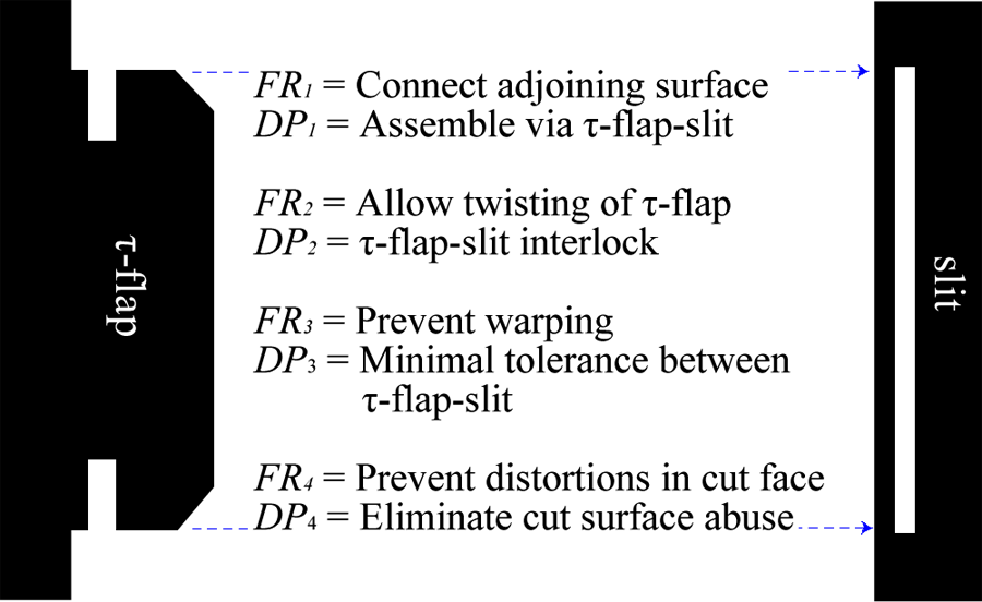
High-level set of nFR and plausible nDP.
The design relationship between nFR and nDP can be expressed in matrix notation form
12
as in equation (1), where the left-hand array is the domain or vector with m functional requirements; the right-hand array, {DP}
p
×1, co-domain is the vector of design parameters with p characteristics; and

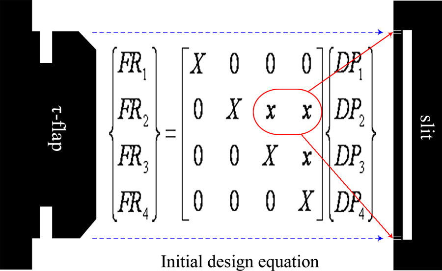
Thus, the nFR statements and respective plausible nDP in Figure 1 may be represented by the initial design equation (2) in which X denotes a strong relationship between a domain and respective co-domain 14
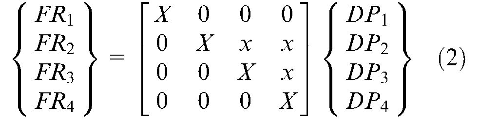
The weak relationship, x, between FR2 and DP2 (Figure 2) denotes the required minimum tolerance of the slit to accommodate and allow twisting of the τ-flap. As this is necessary for the purpose of initial inspection of component alignments, there is no need to decompose FR2. However, the x between FR3 and DP3 is seen as a quality indicator which relates to the level of structural warping. This is therefore not negligible. A violation of FR3 can compromise warping stiffness which may consequently translate into an extreme tilting of a τ-stoss technology assembled lorry due to the centrifugal force along a curve. In this respect, there is a need to further specify design requirements to ensure warping stiffness, leading to material stability. This warrants decomposing FR3 into FR3 n in order to map out the plausible DP3 n (Figure 3).
Weak relationship, x, between FR2 and DP2.
Decomposition of FR3 to achieve material stability.
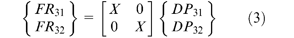
The decomposition analysis in Figure 3 yields the design equation (3)
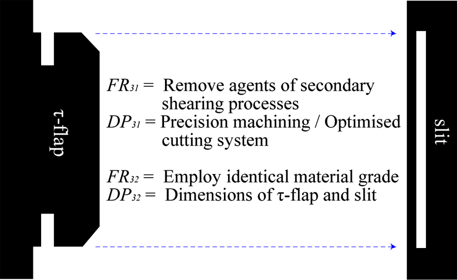
In order to achieve high surface integrity of adjoining edges, FR31 was further decomposed (Figure 4) to identify the specific functional processes required for optimal machining and τ-stoss technology-based components assembly.
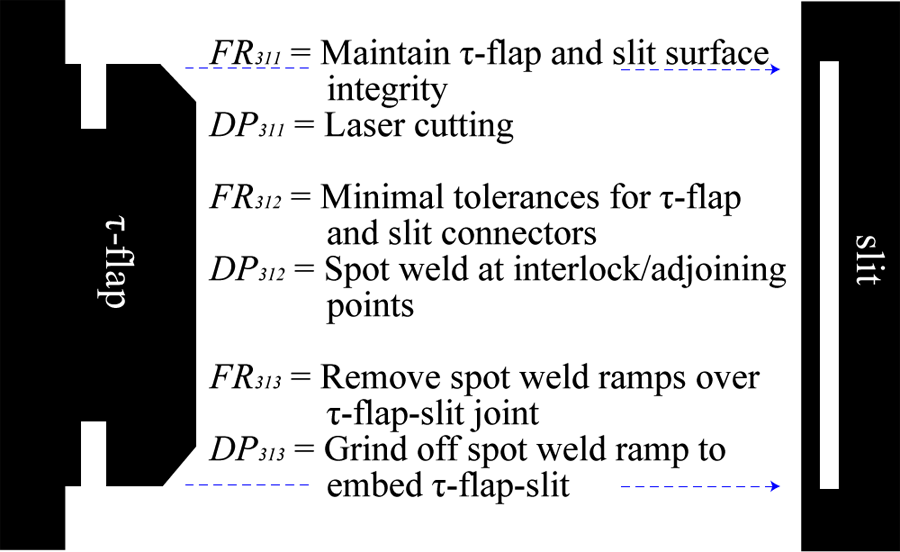
Decomposition of FR31 and plausible DP31 n .
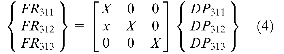
The decomposition of FR31 leads to equation (4)
To satisfy FR32, autobody panels of identical material grade were selected. This was to ensure that the mechanical properties remained practically uniform throughout the machining process and overall body component.
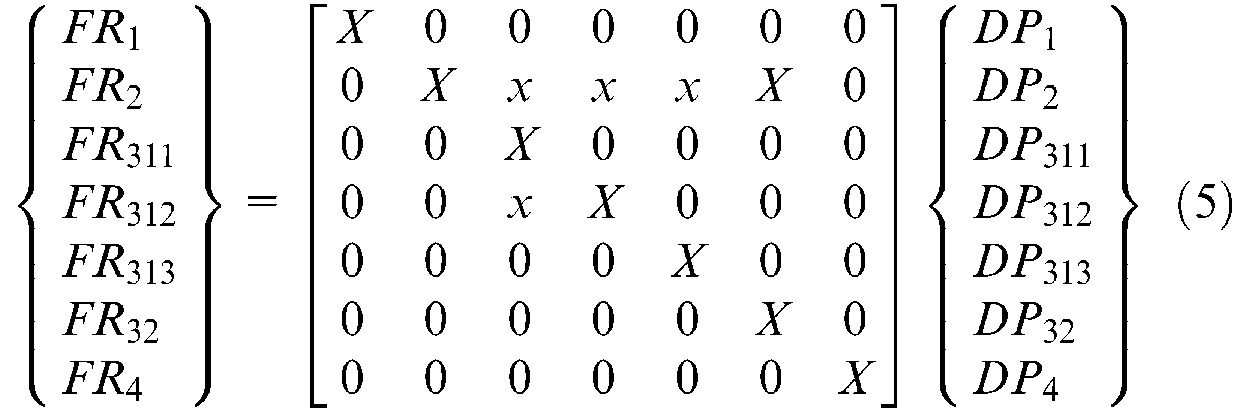
Equations (2) to (4) yield a master decoupled or robust design matrix that may be described by equation (5)
Methods and results
τ-stoss automotive body components assembly
In order to satisfy FR311, a computer-controlled laser cutting system (DP311) was selected as the choice to machine the workpiece. This was the ideal choice to prevent any secondary shear process, usually induced by conventional machining operations, that could potentially lead to draw-ins or burr projections at the cut surfaces of steel sheet. 2 To align matching adjoining component surfaces as well as to follow a step-by-step assembly process, each element of the design was coded with a reference number in CATIA V5. The vehicle design file was converted into a dxf file extension and emailed to the laser cutting service provider. To prevent any complexity in the supply chain, the panels were machined such that they were delivered in flat forms. This is because complex contoured surfaces can compromise space and increase cost for handling and delivery.
An interactive guided mode for assembling the autobody main structures was created within the CATIA V5 environment. This enabled:
a bill of materials (BOM) implosion that directly relates number-coded panels (Figure 5(a), for example) to respective main structures or substructures;
a BOM explosion that breaks each assembly or sub-assembly into its component parts.
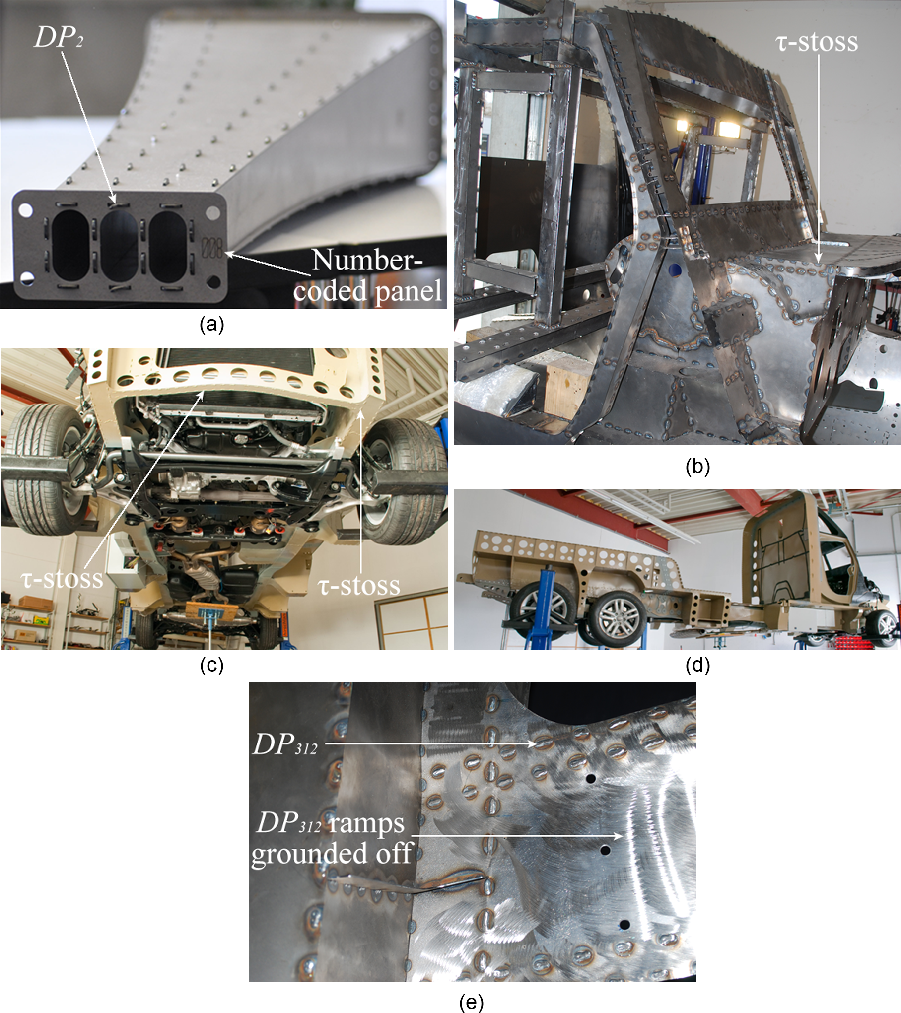
Applying τ-stoss technology leads to high strength in adjoining panels: (a) number-coded panels in front rail, (b) τ-stoss connections at the vehicle front cabin, (c) τ-stoss reinforced chassis, (d) τ-stoss in identical steel grade, and (e) DP312 ramps ground to satisfy FR313.
Referring to the BOM, number-coded autobody panels were picked and joined manually by inserting τ-flaps into respective slits through DP1 and DP2 to satisfy both FR1 and FR2. For example, a single-level BOM displayed the components needed to assemble the front cabin of a vehicle (Figure 5(b)). The τ-flaps were twisted off to create a temporary primary beam interlocking (DP2) element between any two deformable shells, rigid bodies or rigid-deformable structures or subsystems. A spot weld, DP312, serving as a secondary beam, was manually applied to DP2 to form a permanent rigid-body joint called a τ-stoss (Figure 5(c) and Figure 5(d)). This subsequently increased structural stiffness; and where necessary, the DP312 ramps were ground off to embed the τ-stoss (DP313) between the adjoining panels (Figure 5(e)).
Results and discussions
In order to obtain preliminary data on crashworthiness, the authors modelled and conducted a LS-DYNA crash simulation analysis of 2 mm (12.45 kg) and 3 mm (22.79 kg) thick τ-stoss technology-based steel front rails (crash nosecones) travelling at 14.01 m/s to collide against a stationary rigid wall. 14 The deformation history, reported by Flowers and Cheng 14 showed that a high number of τ-stoss assemblies/connections/joints in the 3 mm steel crash nosecone prevented failure at the integration points. To validate robustness and reliability of the nDP that fulfilled all the nFR of the τ-stoss technology assembled autobody, and stability of the vehicle, a series of test drives (Figure 6) were conducted on straight, curvilinear and off-road courses. The ability of a lorry to successfully negotiate a curve is a function of the lorry’s speed, loaded stability and the geometry of the curve. 15 As such, the lower level roots of the hierarchical structure of FR3, for example, ensured stiffness in the vehicle body and thus prevented tilting that could have resulted in a potential rollover of the lorry due to the centrifugal force along the curve.
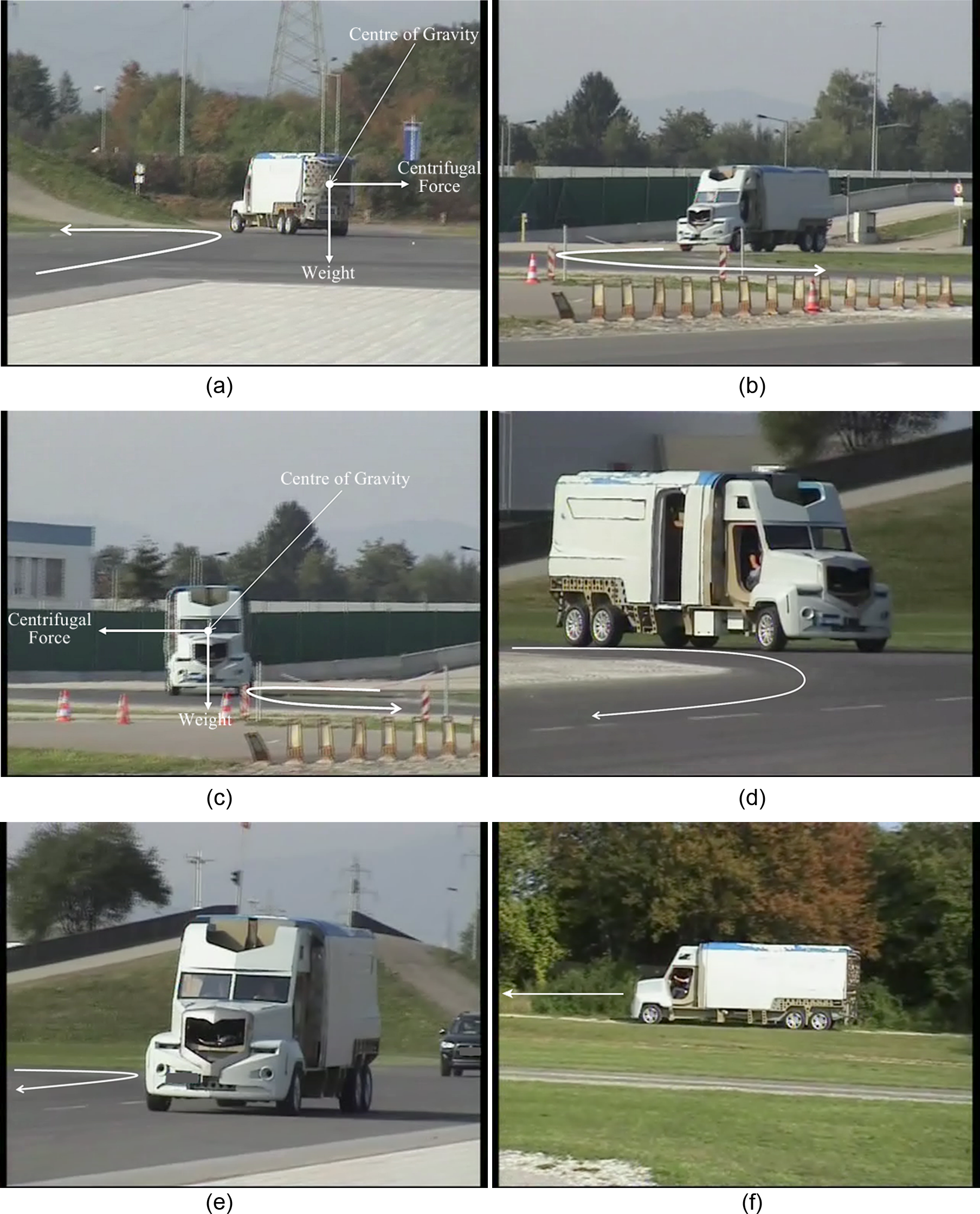
Test drives of τ-stoss technology-based automobile (a) τ-stoss assembled lorry negotiating a curve, (b) vehicle exhibits stability in a curve, (c) warping stiffness prevents body from tilting, (d) achieving all nFR prevents rollover, (e) vehicle is stable while moving in a straight line, and (f) τ-stoss assembled lorry is stable during off-road manoeuvres.
Although the tailor welded blank (TWB) technique offers highly reinforced adjoining surfaces of autobody components of different material grades, 16–18 it will be challenging to design an environmentally friendly, cost-effective, efficient and reliable manufacturing system for the required laser welding operation within a sustainable manufacturing context. This is because the TWB process involves joining different autobody component grades that may be subject to various processes in the manufacturing system, making it virtually impossible to evolve decouplers that could create functional independence to satisfy the various sets of nFR. This may present operational vulnerabilities in the context of noise factors, 13 causing functional processes to deviate from the target values. 12
Contrary to the TWB technology, in situations where steel between 1 and 2.5 mm thick may be used in parts of a vehicle body and closure panels simply to reduce weight, 16 the crash analysis of the τ-stoss front rail shows that autobody steel panels of less than 3 mm in thickness may be susceptible to a high degree of material deformation upon impact. 14
Concluding remarks
The axiomatic design theory-based τ-stoss autobody component assembly clearly eliminates a significantly large number of complexity variables – agents of high manufacturing costs and environmental problems – otherwise present in complex traditional car body assembly operations. This is in line with the fact that the factors and metrics of sustainable manufacturing encompass, among others, delivering customer-centric quality products at low cost without any adverse impact on the environment.5–8 On achieving an accurate setup for the chassis (Figures 5(c) and (d)) without employing any major tool except for a clamp and a welding machine, the τ-stoss technology approach to automotive body components assembling does not only eliminate expensive robots and auxiliary tools, machine downtime, material defects and other related product assembly process-induced manufacturing complexities, but also drastically reduces labour costs as the manual assembling personnel do not necessarily need to be highly or technically qualified except for the auto electrician.
Footnotes
Appendix 1
Acknowledgements
The authors would like to acknowledge the support of Roland Crnogorac, KLK (Stuttgart), Germany.