
Abstract
Cutting tool industries face an enormous challenge in finding the conditions that result in economically viable machining of titanium alloys such as Ti-17. The generation of high thermal and mechanical stresses in cutting tools during machining of titanium alloys accelerates tool wear and this significantly affects tool life, productivity and product quality. The application of advanced coatings on cutting tools has become an important way to improve the tool performance when machining titanium alloys. Recently, nano-structured TiAlSiN coatings have attracted increasing attention as an alternative to traditional TiN coatings, mainly due to its superior oxidation resistance at elevated temperatures and improved mechanical properties, which are ideal for machining titanium alloys. Very little attention has been given to the investigation of primary machining operations such as bandsawing. In this investigation, tungsten carbide-tipped bandsaw teeth were coated with TiAlSiN coating. The coating was characterized for structural, chemical and mechanical properties. Machining tests were carried out on Ti-17 alloy in a modified lathe using uncoated and TiAlSiN-coated bandsaw teeth. Forces were measured during the cutting tests and the specific cutting energy was calculated using the obtained force and material removal rate data. Wear modes and mechanisms in the bandsaw teeth were investigated using a scanning electron microscope and energy dispersive X-ray analysis. The results show that a TiAlSiN-coated bandsaw tooth performed better than an uncoated bandsaw tooth in terms of wear and specific cutting energy.
Introduction
The appealing properties of titanium alloys such as their excellent strength to weight ratio, fracture resistance, corrosion resistance, low density and ability to retain high strength levels at elevated temperatures has resulted in numerous industrial applications particularly in the aerospace industry.1–3 However, it is a significant challenge to machine these alloys in an economic manner and in fact they are classified as difficult-to-cut materials. Their low thermal conductivity (86% lower than that of steel) causes the machining heat to be concentrated at the tool’s cutting edge. Furthermore, at the high temperatures generated during machining, titanium alloys have a strong chemical affinity with most of the tool materials. This leads to strong adhesion of workpiece material on the tool edge. In addition, the ability of titanium alloys to maintain high strength levels even at elevated temperatures results in excessive stress on the cutting tool. These unique machining characteristics of titanium alloys generate higher cutting forces and temperatures in the cutting tools resulting in accelerated tool wear, plastic deformation, premature tool failure etc. which also affects the workpiece surface finish and surface integrity. 4
Tungsten carbide is still considered to be the best tool material for machining titanium alloys based on the tool performance, tool cost and machined surface quality. 5 Typical wear and failure modes in Tungsten carbide tools observed during machining titanium alloys are flank wear, crater wear, chipping, notching and catastrophic tool failure. The mechanisms of tool wear are mostly attributed to adhesion, attrition and diffusion.6–10 In general, the machining of titanium alloys with carbide tools is carried out at low cutting speeds that range from 30 to 100 m/min due to rapid tool wear 11 and the consequence of this is a low productivity level. The current trend is to apply advanced coatings on carbide tools. The coating enhances the hardness of the tool surface resulting in an increased wear resistance. The low coefficient of friction of the coating reduces the adhesion of the workpiece material on the tool. Furthermore, the coating acts as both a thermal and a chemical barrier, which reduce the oxidation and diffusion of tool materials. Therefore, with coated carbide tools, higher cutting speeds can be used to machine titanium alloys leading to higher productivity levels.
In the last few decades, titanium-based binary and ternary coatings such as TiN, TiCN, TiAlN etc. have been successfully applied to cutting tools in order to enhance their performance and lifetime. However, in harsh cutting environments such as machining difficult-to-cut materials, high-speed machining, dry machining, etc., these coatings cannot always offer the beneficial effects of hot hardness, oxidation resistance and chemical stability. More recently, advanced nano-structured coatings such as quaternary TiAlSiN, has attracted a lot of research interest as it can combine superior hardness, oxidation resistance, thermal stability and toughness properties.12–18 Several studies have confirmed the beneficial effect of a TiAlSiN coating compared with traditional coatings in tribological wear tests19,20 and in practical machining applications (e.g. turning, milling and drilling).21–24
While considerable attention has been paid to secondary machining operations (e.g. turning, milling, drilling etc.), very little and in some cases no attention has been paid to primary machining operations (e.g. bandsawing). There is an extensive literature on bandsawing and it is a well understood machining operation.25–27 The characteristic features of material removal in a bandsawing operation are a result of a cutting edge with a limited sharpness (5 to 15 µm) and the removed layer of material being very small (5 to 50 µm). Furthermore, the chips formed during a bandsawing operation have to be accommodated in the gullet and ejected at the end of the cut. This situation can lead to an inefficient metal removal operation as a result of the combined effect of piling up, discontinuous chip formation and ploughing action in contrast to most single-point cutting operations (e.g. turning). Most of the bandsawing studies reported in the literature have been focused on the machining of steel workpieces using bimetal high-speed steel bandsaws. Very little information is currently available in the public domain on the bandsawing of titanium alloys. 28 Therefore, more scientific data is needed to allow the machining characteristics of titanium alloys to be ascertained. This will assist in minimizing the cost per cut when cutting titanium alloys with bandsaws. The aim of the current investigation is to evaluate the effect of an advanced nano-structured TiAlSiN coating on a carbide-tipped bandsaw on its performance when machining titanium alloy.
Experimental procedure
Workpiece material
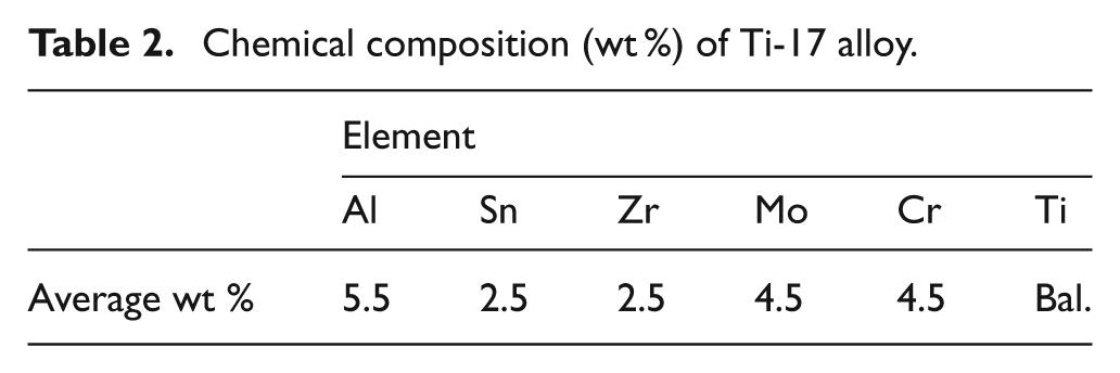
Beta-rich alpha-beta Ti-17 alloy was considered as the workpiece material for this investigation as it is widely employed in aeroengines. Relevant properties of Ti-17 alloy are shown in Table 1. 29 The chemical composition of the workpiece material was obtained using energy dispersive X-ray (EDX) spectroscopy and the results are presented in Table 2.
Mechanical properties of Ti-17 alloy.
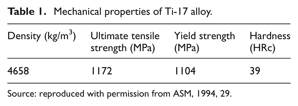
Source: reproduced with permission from ASM, 1994, 29.
Chemical composition (wt %) of Ti-17 alloy.
Cutting tool
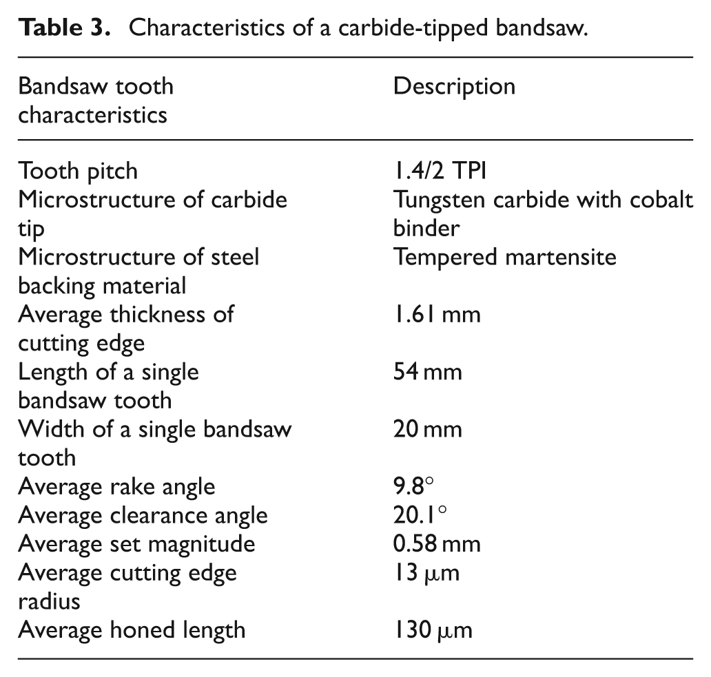
Tungsten carbide-tipped bandsaw teeth were used for the machining tests. A picture of the bandsaw tooth geometry is presented in Figure 1. It should be noted that the bandsaw teeth were honed to create a small flat on the clearance side. The geometric features of bandsaw teeth used in the machining tests were characterized and they are presented in Table 3. A number of the bandsaw teeth were coated with a TiAlSiN coating using an arc evaporation system at a deposition temperature of approximately 450 °C.
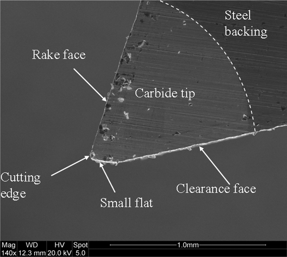
Bandsaw tooth geometry.
Characteristics of a carbide-tipped bandsaw.
Coating characterization
Coating thickness, surface morphology and fractured cross-sectional microstructure were assessed using a scanning electron microscope (SEM) (FEI Quanta 200 ESEM with tungsten filament). The chemical composition of the coating was analysed using an Oxford Instruments EDX spectrometer fitted to the SEM. The crystal structure of the coating was determined using the glancing angle X-ray diffraction (GAXRD) technique with an angle of incidence of 2°. A Cu-Kα radiation source was operated at 40 kV and 40 mA to generate X-rays with a wavelength of 0.15405 nm. Nanoindentation tests on the coating were performed using a Hysitron Triboindenter fitted with a Berkovich indenter (tip radius of 100 nm). The maximum indentation depth was less than 10% of the coating thickness to avoid any effects from the substrate. Adhesion of the coating was evaluated qualitatively using a Rockwell C indenter under a load of 1471 N. Scratch tests were also carried out with a loading rate of 100 N/min and an indenter transverse speed of 10 mm/min.
Cutting test procedure
Full product bandsaw testing is complex, expensive and time-consuming. In the current work, the performance of uncoated and TiAlSiN-coated bandsaw teeth was evaluated using a single tooth time compression technique, which used a single bandsaw tooth instead of the complete bandsaw blade. 30 A modified lathe machine was used as the machining setup and four sections of workpieces were attached in the chuck to simulate the interrupted cutting action in bandsawing. The width of cut for all the tests was set to be approximately 1 mm, which is less than the average tooth tip thickness (Table 3). In addition, a depth of cut or feed of 10 µm and a cutting speed of 40 m/min under a flood cooling condition were chosen for the tests. The authors have previously established that the selected machining parameters maximize bandsaw tool life. 28 Cutting forces were measured during the tests using a Kistler dynamometer and associated electronic equipment. The wear modes, wear mechanisms and wear length in the bandsaw teeth were investigated using the SEM.
Results and discussions
Coating characteristics
EDX spectroscopic analysis showed that the atomic percentage of the elements in the TiAlSiN coating was very close to the stoichiometric value (Figure 2). The atomic percentage of Ti was highest, whereas Si was the lowest (5.37 at %). It has been reported in the literature that the best properties of a TiAlSiN coating can be achieved when the Si content is in the range 5–12 at %.14,15,19,21,31
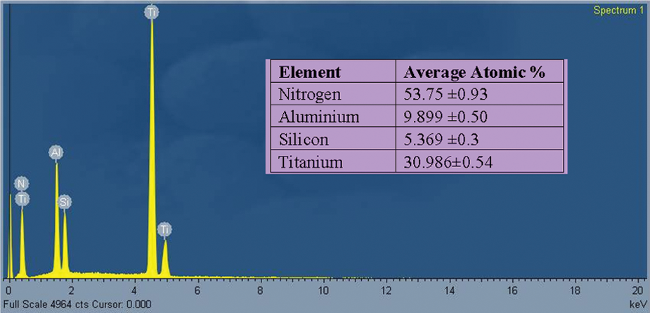
EDX spectrum of elemental composition in TiAlSiN coating
The GAXRD pattern of the TiAlSiN coating presented in Figure 3 reveals that the coating exhibits a single-phase face centred cubic structure, which is very similar to the structure of the TiN coating. Several peaks are observed that have different directions with the preferred orientation being in the {200} plane. No peak associated with the {111} plane can be observed, although the preferred orientation in a pure TiN coating is generally seen in that direction. Many researchers have suggested that the change in preferred orientation to {200} in a TiAlSiN coating is a result of a reduction in grain size.12–15 No peaks associated with the AlN phase can be observed, which is probably due to the low Al content in the coating. The diffraction pattern also contains a number of peaks from the tungsten carbide substrate. There are, however, no signals from other crystals, such as Si x N y or titanium silicide, suggesting that Si is present as an amorphous phase in the Si or Si x N y matrix. It is believed that some of the Ti atoms in the TiN lattice are replaced by Al and Si atoms forming a solid solution phase or Si atoms are partially segregated to form an amorphous Si3N4 phase.12,14 Peak broadening can be observed in the diffraction patterns, which in general indicates a reduction in grain size or the development of residual stresses in the lattice.13,21,22 The average grain size of the crystallites in the coating was calculated to be approximately 8 nm, which is in agreement with the work reported in the literature on TiAlSiN coatings deposited by cathodic arc evaporation.16,17,20
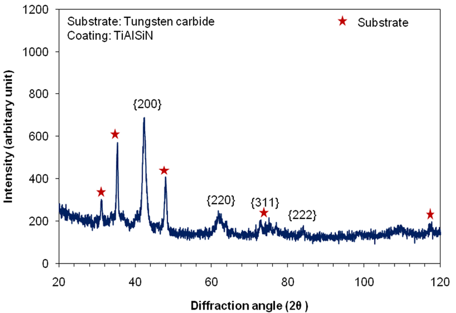
X-ray diffraction pattern of TiAlSiN coating
The surface morphology of the coating exhibits micro-pores and droplets, which are characteristic of cathodic arc evaporation processes (Figure 4(a)). The cross-sectional microstructure presented in Figure 4(b) demonstrates that the TiAlSiN coating was deposited as a single-layer coating with a dense and non-columnar microstructure. This is believed to be the result of grain refinement due to the incorporation of Si in the coating.14,20 The smaller grain size found in the GAXRD results also supports the possibility of grain refinement in the coating. The thickness of the TiAlSiN coating was calculated to be approximately 2 µm using the image analysis software supplied with the SEM.
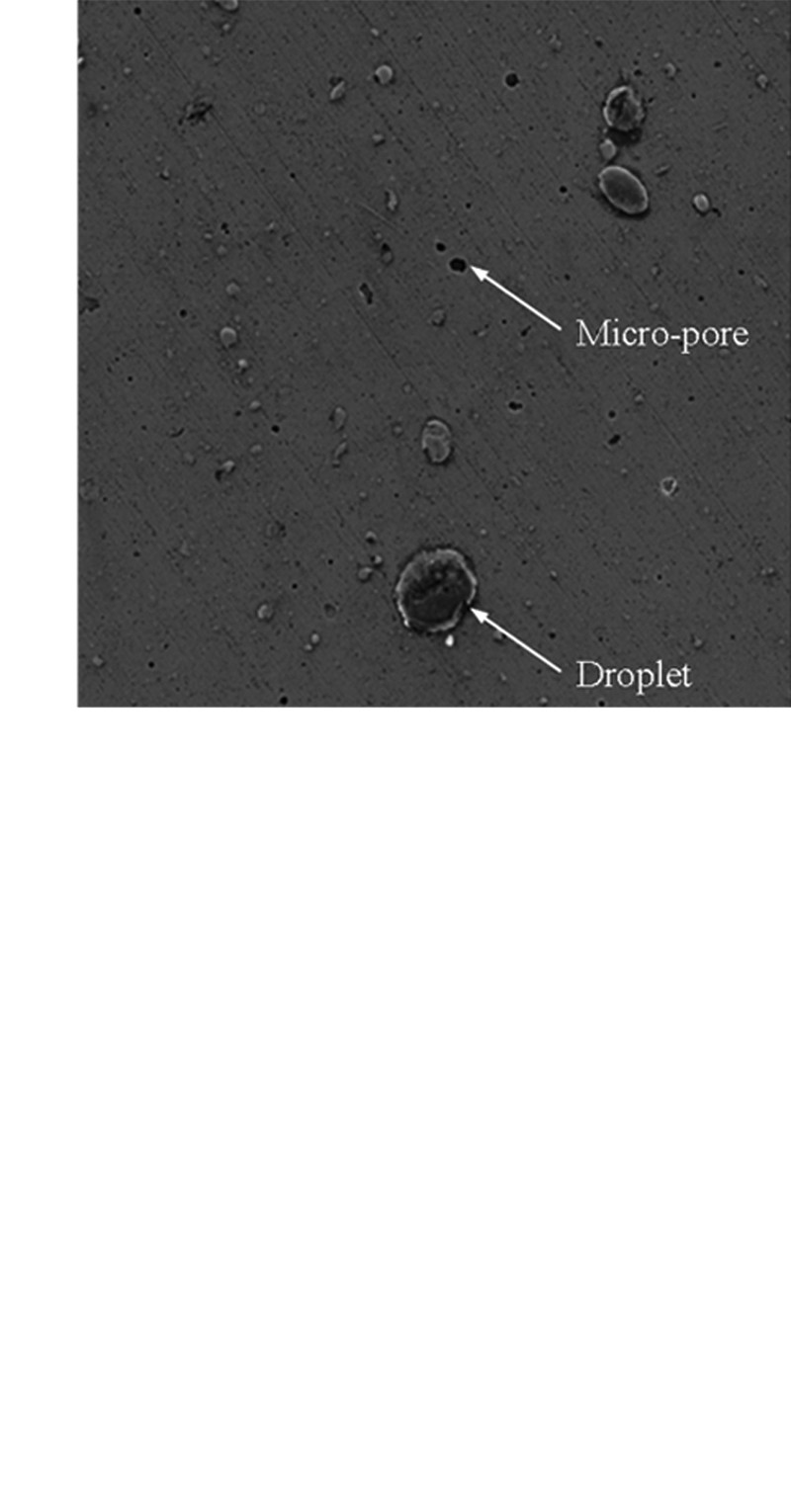
SEM images of TiAlSiN coating (a) surface morphology, and (b) fractured microstructure.
The hardness and modulus of the coatings were found to be 35.84 ± 9 and 348.87 ± 56 respectively. Similar values have been reported in the literature for TiAlSiN coatings deposited on tungsten carbide substrates using the cathodic arc evaporation technique.19,20 A high hardness level is generally attributed to being the result of the presence of nano-sized crystallites in the coating. The hindrance of dislocation movements and the absence of dislocation at small grain sizes can result in higher hardness values. 15 Solid solution hardening due to the dissolution of Al and Si atoms in the TiN crystallites could also be responsible for high hardness values.14,17 Furthermore, the grain boundary strengthening (also known as the Hall–Patch effect) created by a strong cohesive energy at interphase boundaries would lead to a high value of hardness in the coating.20,22
The Rockwell C indentation tests performed on the coating revealed very small cracks with no delamination of the coating around the indentation (Figure 5(a)). This indicates that the coating is tough and is well adhered to the substrate. The higher critical load (∼ 68 N) for coating failure found in the scratch test also supports the finding of the Rockwell C test. Also, the lack of any evidence of brittle fracture around the scratch track emphasises the good toughness of the coating (Figure 5(b)).
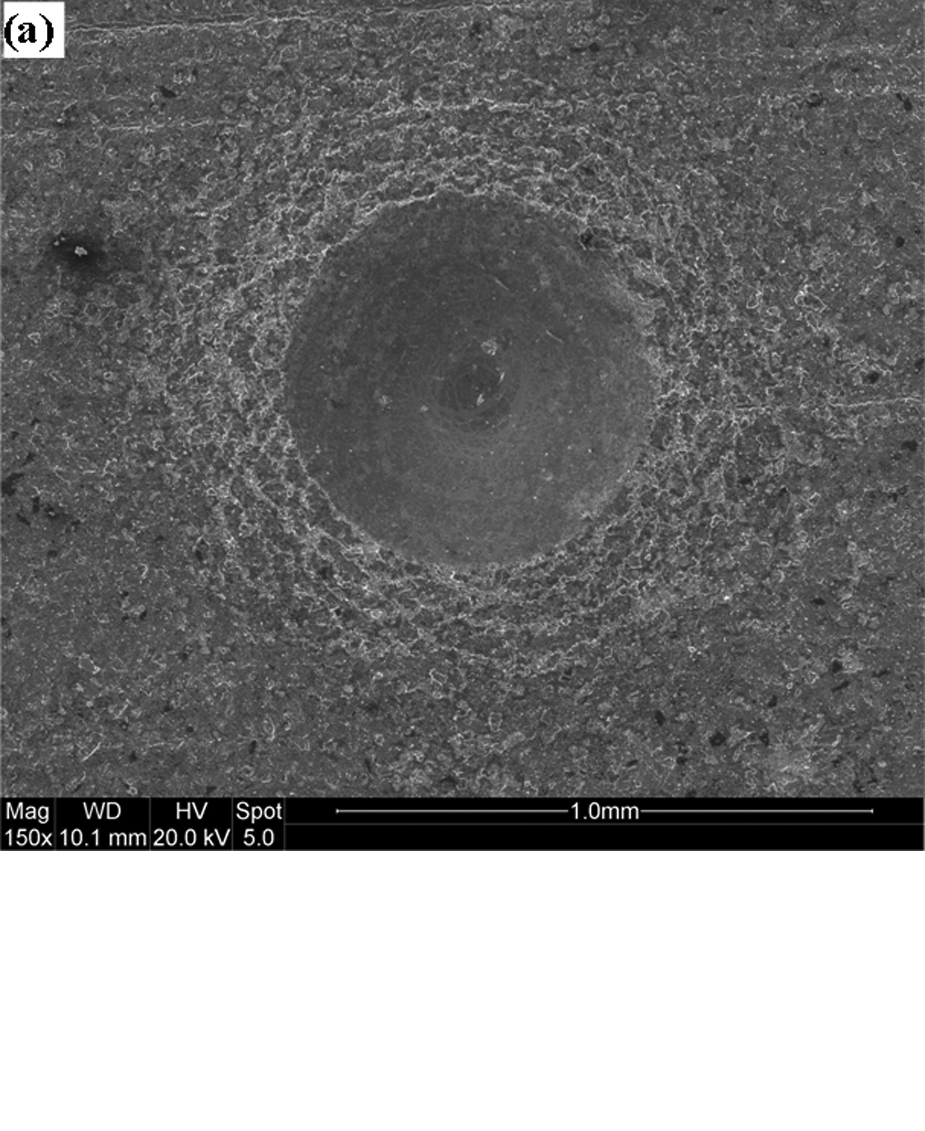
Micrographs of (a) Rockwell C indentation, and (b) scratch track generated in the coating.
Wear and failure modes in bandsaw teeth
In order to determine the wear and failure modes and to compare the condition of the uncoated and TiAlSiN-coated bandsaw teeth, the machining test was periodically interrupted and finally stopped after cutting 5700 m. Figures 6(a) and (b) show magnified corners of the bandsaw cutting edges. From these figures corner wear and flank wear are identified as the principal wear modes in bandsaw teeth. The maximum wear appears at the corner of the cutting edge that was engaged with the workpiece and gradually decreases across the thickness of the cutting edge. This could be due to the engagement of the cutting edge at an angle with the workpiece which is a consequence of the set geometry (set and twist angles) of the bandsaw tooth. Furthermore, the width of cut (1 mm) was smaller than the thickness of the cutting edge (1.6 mm).
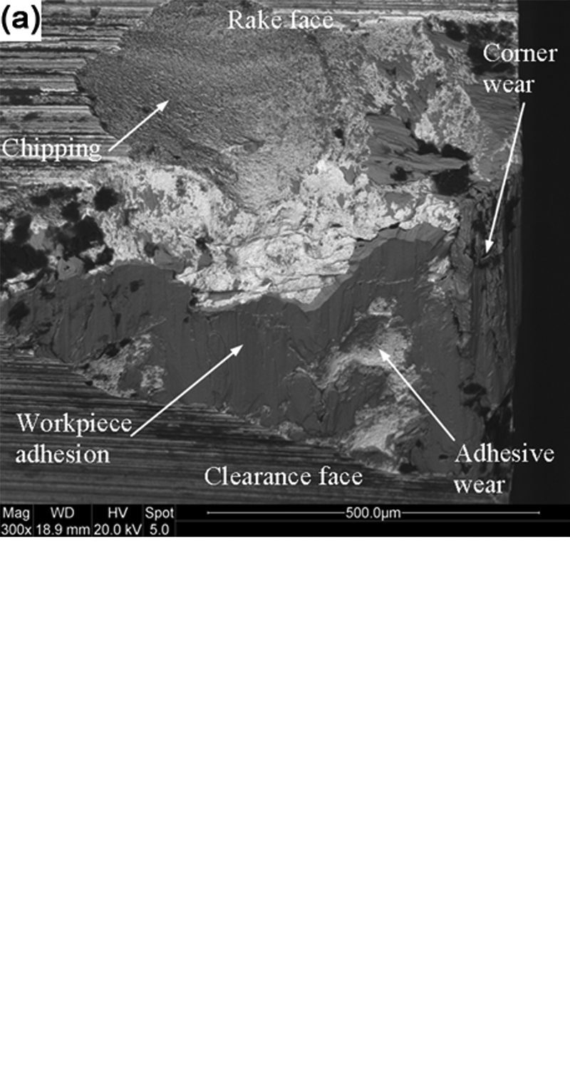
Magnified images of the corner of bandsaw teeth after 38,000 cuts (a) uncoated edge, and (b) TiAlSiN-coated edge.
A higher load at the corner would generate a higher stress level and temperature. This could reduce the yield strength of the tool material and result in an accelerated wear at the corner. 4 It is evident that the cutting edge in the uncoated tooth is completely damaged with non-uniform wear extending in both rake and clearance faces along with severe corner wear. On the other hand, the cutting edge in the coated tooth is still intact after completion of the machining test with uniform wear on the flank face only and less severe wear at the corner. The corner wear length in the uncoated tooth at the end of the machining tests is approximately three times higher than the wear length in the coated tooth (Figure 7).
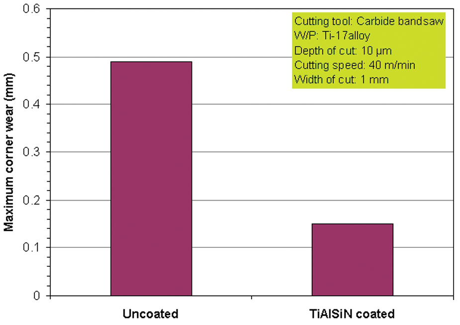
The comparison of durability between the uncoated and TiAlSiN-coated bandsaw teeth in terms of corner wear.
Chipping on the rake face is observed as the main failure mode in both the uncoated and TiAlSiN-coated teeth. However, the extent of chipping is much higher in the uncoated tooth causing a catastrophic failure of this tooth. Cyclic mechanical and thermal loading due to the periodic engagement and disengagement of the tooth with the workpiece during machining are generally cited as the reasons for the creation of the chipping phenomenon.4,6,9,10 The brittle characteristic of the carbide material could also be a contributing factor for the occurrence of chipping.
Another failure mode in the form of a microcrack can be observed in the bandsaw cutting edge shown in Figure 8. The interrupted cutting condition and the generation of high temperatures during the bandsawing test could be responsible for the generation of cracks. After the generation of initial cracks, they could further extend into the carbide tip with prolonged machining and finally lead to chipping of the edge. However, it must be stated that chipping can take place without the formation of cracks. 10
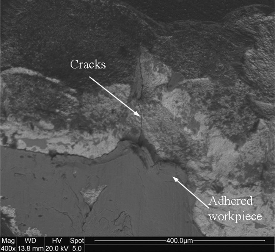
Bandsaw cutting edge showing cracks.
Therefore, it can be concluded that wear and failure in the bandsaw teeth are caused due to the high stress and temperature generated during machining the titanium alloy. The TiAlSiN coating can reduce chipping, cracking etc. and result in more controlled and stable flank wear.
Wear mechanisms in bandsaw teeth
The SEM images in Figures 6(a) and (b) exhibit clear evidence of the workpiece material adhering to the cutting edge. The high temperature and stress generated during machining caused the welding of the workpiece material to the cutting edge. The process also led to the modification of the cutting edge. 32 The amount of workpiece material adhering to the bandsaw could affect the cutting force. When the adhered layer attained a critical size it was detached from the cutting edge along with tool material and was removed with the flowing chip. This process increases the wear and also encourages the chipping of the bandsaw cutting edge.
Attrition is also identified as another dominant wear mechanism for the cutting edge of the bandsaw. Attrition is defined as the process of removing particles or grains of tool material by adherent chip or workpiece.6,10 The uneven wear on the worn cutting edge is evidence that fragments of the tool have been plucked away by the adhering workpiece material or flowing chip (Figure 9). The attrition wear process causes a gradual increase of wear in the cutting edges.
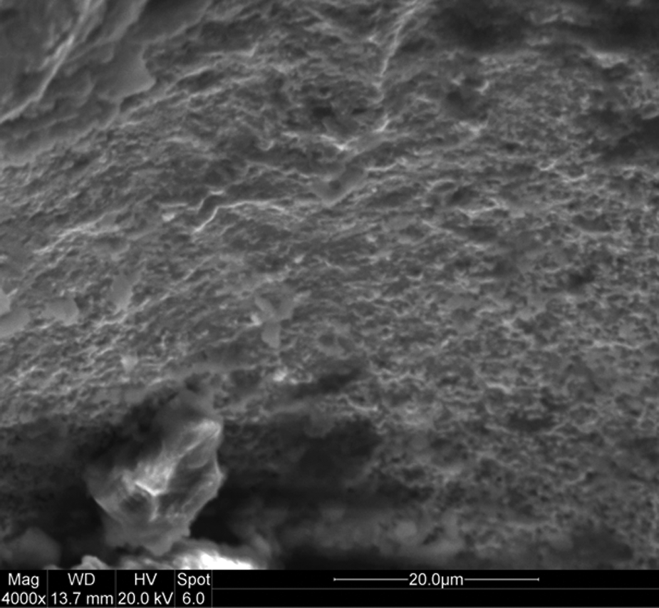
SEM micrograph of bandsaw cutting edge showing attrition wear.
In addition to adhesion and attrition, diffusion wear was identified by the elemental analysis of the workpiece material adhered to the worn tool. The SEM images of the analysed area and the corresponding EDX spectrum are shown in Figure 10. The presence of carbon (C) and cobalt (Co) in the adhered material indicates that diffusion of the elements from the carbide tool into the workpiece material took place at the tool–chip interface, therefore confirming diffusive wear. The high stress and temperature at the tool workpiece contact point created a favourable environment for the diffusion of tool elements. Similar results have been reported in the literature for the situation of machining titanium alloy with carbide tools.5,6,33 Diffusion in tungsten carbide can start at a temperature as low as 400 °C. 8 The machining of a titanium alloy using carbide tools, even under moderate cutting conditions, can generate temperatures at the tool edge that exceed 400 °C. In the event of diffusion, the loss of C and Co from the carbide tool results in a weakened tooth which accelerates wear. However, no sign of diffusion of the heavier element (tungsten) is evident in the EDX spectra. This could be an indication of mild diffusion process as moderate cutting speed and low feed per tooth were used in the bandsawing tests.
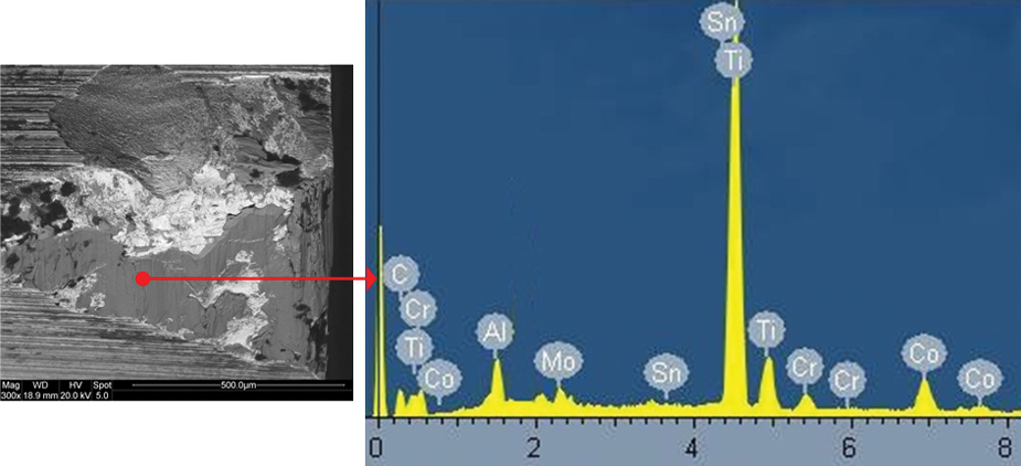
EDX spectrum of workpiece material adhering on the bandsaw cutting edge providing evidence of elemental diffusion.
In contrast with the observed behaviour created by the uncoated bandsaw tooth, the removal of coating mainly from the flank face can be identified as the initial wear mechanism for the TiAlSiN-coated bandsaw tooth. This could be due to the interaction between the coating and the machined workpiece. The removal of the coating takes place in a gradual manner exposing the substrate without any flaking or premature delamination of the coating. Subsequently, the exposed substrate is subjected to adhesion, attrition and diffusion wear phenomena. However, the remaining coating on the rake and flank face acts as a barrier to slow down the progression of further wear. The quantity of adhering workpiece material can be seen to be higher on the uncoated tooth compared with that for the TiAlSiN-coated tooth (refer to Figure 6) possibly due to the high heat resistance, chemical resistance and lower friction characteristics of the coating. Hence, the coating provides continuous resistance against wear, leading to a much more predictable tool life, reduced risk of unexpected failure and extended tool life.
Specific cutting energy
The specific cutting energy (Esp) parameter is a measure of the energy required to remove a unit volume of workpiece material and it thus is a reflection of the efficiency of the cutting process. Moreover, Esp can be used to correlate various stages of tool wear to the performance of the bandsaw teeth, as it is more sensitive to low depths of cut, which is the case in bandsawing operations. 34 Figure 11 shows the variation of Esp with the length of cut produced. The Esp value was calculated with the data associated with cutting force and material removal rate. For both uncoated and coated bandsaw teeth, Esp values increase with the length of cut due to progressive wear in the cutting edges. The tool wear and degradation result in modification of the cutting edge (i.e. blunting, higher edge radius), which increases the cutting force and hence produces a higher Esp. 25 Moreover, the contact length between the clearance face and machined workpiece increases due to the flank wear. This results in increased friction and hence a higher cutting force/Esp.
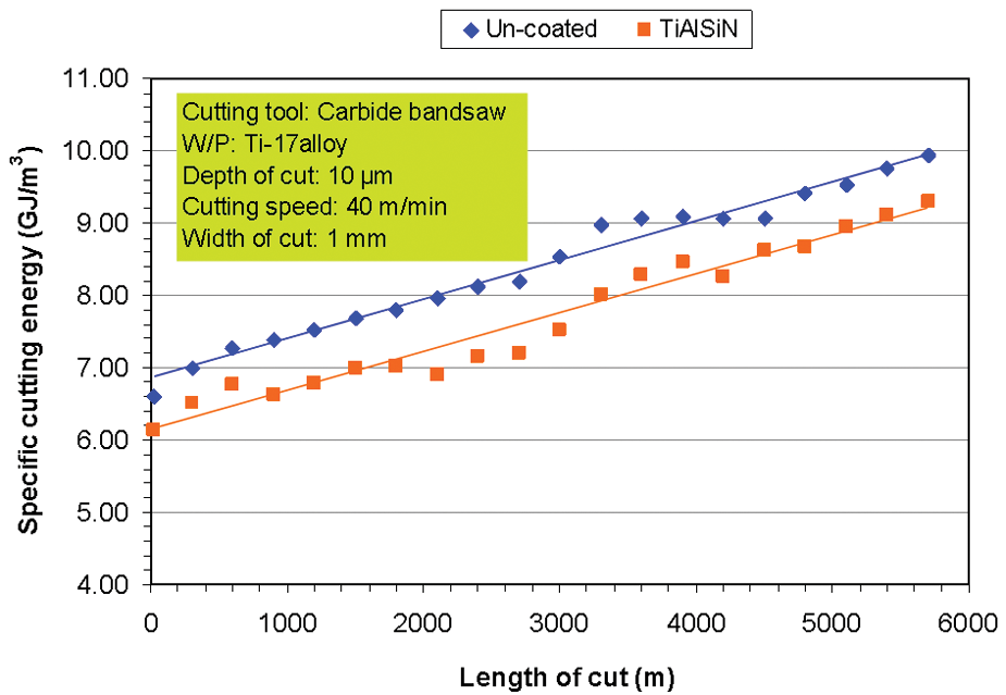
Comparison of specific cutting energy (Esp) as a function of the length of cut for the uncoated and TiAlSiN-coated bandsaw teeth.
At the new condition of the uncoated tooth, the Esp value was measured to be 6.2 GJ/m3 and reached a maximum value of 10 GJ/m3 at the end of the machining test. However, the Esp values for the coated tooth always remain lower than that for the uncoated tooth. This could be a result of the fact that the coating limited wear and degradation of the cutting edges due to its high hardness, high oxidation resistance and low coefficient of friction.
It should also be noted that a small cyclic trend can be observed in the Esp values as a function of the length of cut. This could be due to the periodic adherence and removal of workpiece material on the flank face. The modification of the cutting edge due to the adhering workpiece material causes the force/Esp to increase; 32 however, the Esp value subsequently decreases once the original tooth geometry is restored through the removal of the adhering workpiece material during machining.
Conclusions
The following conclusions can be drawn based on the cutting tests conducted with uncoated and TiAlSiN-coated bandsaw teeth on Ti-17 alloy.
A crystalline TiAlSiN coating was deposited on the bandsaw cutting edge with a dense microstructure, high hardness and good adhesion to the bandsaw teeth.
The coated bandsaw tooth performed better than the uncoated tooth in that it maintained the structural integrity of the cutting edge unlike the rapid degradation observed for the uncoated cutting edge.
Flank wear, corner wear, chipping and cracking were identified as the principal wear and failure modes which controlled the life of carbide-tipped bandsaw teeth.
The dominant wear mechanisms were adhesion and attrition at the bandsaw cutting edge. Diffusion wear mechanism was also identified by EDX analysis.
No well defined built-up edge was observed for either the uncoated or the coated teeth. However, the quantity of the adhering workpiece material was found to be higher on the uncoated tooth compared to the coated tooth.
The coated tooth indicated a better machinability characteristic as evidenced by lower specific cutting energy in the coated tooth.
Footnotes
The authors would like to thank Northumbria University and SNA Europe for supporting this research.