
Abstract
To enhance CFRP-aluminum alloy thin plate joint strength, this study proposes a novel hybrid riveting method. It involves 3D-printing multi-row micro-metal rivets on aluminum substrate, embedding them into carbon fiber fabric, and co-curing via vacuum-assisted resin transfer molding to form a joint integrating mechanical interlocking and adhesive bonding. Single-factor experiments with rivet row number (0, 1, 2, 3) as the variable evaluated mechanical performance and failure mechanisms. The single-row configuration achieved 7.54 MPa lap shear strength, 650.2% and 408.7% higher than adhesive-only (1.01 MPa) and surface-treated adhesive (1.43 MPa) groups, respectively. Strength showed a non-linear trend (1 > 3 > 2), while elongation increased with row number. Failure analysis revealed interfacial debonding for rivet-free specimens and aluminum substrate fracture for riveted ones. The non-linear strength behavior stems from multi-row rivet bridging and localized bending. This technique significantly improves CFRP-aluminum bonding.
Keywords
Introduction
CFRP composites have emerged as viable lightweight solutions for structural applications owing to their high specific strength and stiffness. By partially replacing metallic components with lightweight CFRP, weight reductions of 30–40% can be achieved.1,2 In recent years, the use of CFRP in industrial sectors has grown significantly, with hybrid polymer-metal structures demonstrating considerable potential for reducing energy consumption and emissions.3–5 Consequently, achieving reliable connections between dissimilar materials and metal components has garnered increasing attention. Since McLaren produced the first carbon fiber composite monocoque for Formula One racing cars in 1981, the application of composite materials in the automotive industry has gradually expanded.6,7 Lightweighting of automobiles has become a major research and development focus, with the vehicle body, which represents a substantial portion of the total weight, being a primary target for weight reduction. In line with this goal, multi-material composite body structures have emerged as a new trend in automotive body technology. 8 Among various material combinations, the lightweight pairing of aluminum alloys and CFRP is in high demand across fields such as automotive and aerospace engineering.9,10 Accordingly, development of efficient joining techniques for aluminum and carbon fiber composites has become an active area of research.
Currently, the joining of dissimilar materials, such as CFRP and aluminum alloys, primarily relies on three conventional techniques: adhesive bonding, mechanical fastening, and fusion welding. Mechanical fastening includes bolting and riveting. Bolted connections offer advantages such as high load-bearing capacity, broad material adaptability, detachability, and efficient load transfer.11,12 Traditional riveting is unsuitable for composite materials, leading to the development of self-piercing riveting (SPR), which benefits from ease of automation and relatively high joining efficiency.13–16 However, mechanical fastening requires additional parts, increases weight, and introduces holes into the substrates, resulting in stress concentrations that can compromise joint longevity and strength.17,18 Fusion welding can be categorized into thermal, friction, and induction welding based on the heat source. Laser welding provides concentrated energy, high efficiency, good flexibility, suitability for various joint configurations, and minimal defects.19,20 However, it involves high costs and significant heat input, which can damage the CFRP matrix and cause the formation of voids. Friction lap welding is suitable for large cross-sections and multiple welding positions, offering low cost and strong environmental adaptability, although it suffers from relatively low efficiency and sensitivity to temperature. 21 Induction welding, meanwhile, is less effective for joining thicker components because of the reduction in the effective bonding area as the workpiece thickness increases. 22 Adhesive bonding can avoid stress concentration, 23 extend fatigue life, reduce the number of fasteners, lower structural weight, and provide good sealing performance and material compatibility. However, its drawbacks include low peel strength, limited load-bearing capacity, poor environmental resistance,24,25 non-detachability, the need for surface pretreatment,26,27 long curing times, and residual stresses caused by differences in coefficients of thermal expansion.
To address the various defects in the aforementioned connections, researchers have proposed various solutions. For instance, Du K et al. 28 suggested preparing honeycomb-like porous oxide films through anodic oxidation to reduce the surface energy of aluminum alloy surfaces, making PA6 more easily wettable on the surface of aluminum alloys. The maximum tensile shear strength and fracture energy reached 8.24 MPa and 9.27 kJ m−2, respectively. Akpinar et al. conducted extensive studies on various surface modifications for carbon fibers and fiber fabrics used in adhesive systems, including chemical treatment, electrochemical oxidation, silanization, and adsorption modification with the cationic surfactant.29–33 Anodic oxidation etching and nano-doped epoxy pre-coating were also applied to AA2024-T3 aluminum alloy substrates. The results demonstrated that such treatments significantly improved fiber-matrix interfacial bonding and the mechanical performance of bonded joints, with improvements in joint flexural properties, shear strength, and failure load reaching 23%–30%, 4%–126%, and 5%–41%, respectively. In particular, the combined strategy of electrochemical oxidation and silanization, as well as carbon nanotube doping, achieved performance enhancements ranging from 126% to 177%. Zhang et al. 34 proposed optimizing welding parameters to suppress the formation of micro-pores due to insufficient material flow. The defect rate of the joint was 8.03%, which enhanced the resistance to crack propagation and increased the shear strength of the joint. The maximum lap shear strength of the optimized joint was 32.9 MPa, accounting for 63.1% of the strength of the CFRP substrate.
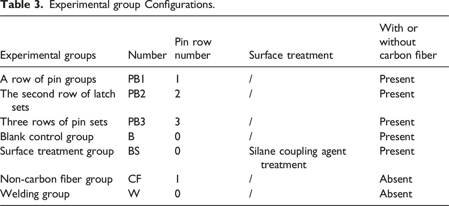
Recent advancements in hybrid connection technology have focused on integrating the advantages of diverse methodologies to achieve synergistic enhancements, thereby realizing outcomes characterized by the “1 + 1 > 2” effect. Techniques such as adhesive riveting and adhesive-welding hybrids have demonstrated superior mechanical performance and durability compared to single-method joints in several studies. Liu et al. 35 investigated the performance and failure mechanisms of self-piercing riveted hybrid joints between CFRP and 5754 aluminum alloy and found that joints with 0°/90° ply orientations performed best, with primary failure modes being adhesive layer and interlock structure failure. Cong et al. 36 proposed a LV-SPR technique, which can increase the shear strength of the joint by 13.5%. Su et al. 37 evaluated the HH-BR technique. The results showed that when connecting CFRP materials with aluminum alloys, this technology had lower strength loss and better energy absorption capacity compared with the H-BR and SPR joints. Wang et al. 38 directly applied ultrasonic vibration to the adhesive, whereby high-frequency impacts were transmitted to the bonding interface, resulting in a 17.2% increase in the bonding strength of the CFRP/nickel joint and inducing a cohesive failure mode. This outcome indicates that the interfacial bonding strength surpassed the interlaminar shear strength of the CFRP substrate. Ohashi R et al. 39 developed a novel riveting process that integrates friction stir spot welding (FSSW) with filler material, resulting in a bell-shaped rivet design that significantly enlarges the rivet head diameter and enhances the interlocking effect of Ti-6Al-4V rivets. Tensile shear tests revealed that both the stir zone produced by filler-assisted FSSW and the flared rivet influence fracture behavior, thereby elucidating the advantages of combining filler-based FSSW with riveting technology. Bao et al. 40 proposed a novel joining method based on metal tapered pins, where pins fabricated on the metal surface are embedded into the CFRP to achieve high-strength mechanical interlocking, avoiding fiber damage caused by conventional drilling, and systematically analyzed the influence of pin height, area fraction, and material on the joint performance. Qin et al. 41 introduced a novel hybrid connection technique that integrates through-thickness reinforcement (TTR) with induction welding. The study examined the influence of micro-pin geometric parameters on the formation and load-bearing performance of hybrid joints. In comparison to welded joints without interlocking structures, 42 the proposed technique achieved enhancements in ultimate strength and energy absorption by 159% and 1758%, respectively. Herein, we propose a novel mechanical-adhesive hybrid joining technique, termed bonded-pin hybrid joining, which is systematically investigated for its performance in joining dissimilar materials and analyzed for its advantages and limitations compared to conventional methods. This study focuses on the feasibility of this technique and the factors influencing its performance, using the number of pin rows as a key variable, with experimental groups designed from 0 to 3 rows of pins, along with control groups involving surface treatment (silane coupling agent) and the absence of carbon fiber. Through single-lap tensile tests, failure mode analysis, and performance comparison with traditional joining techniques, this study comprehensively evaluated the mechanical properties and strengthening mechanisms of this hybrid joining technology, providing an innovative solution for high-performance joining of CFRP/metal lightweight structures.
This technique involves directly 3D printing a regularly arranged array of micro pins on an aluminum plate and embedding them between layers of carbon fiber fabric, constructing a composite joint interface that integrates mechanical interlocking and chemical adhesion. This design avoids substrate damage and the introduction of additional parts associated with traditional mechanical joining, while significantly enhancing the peel and shear resistance of the adhesive bond through physical anchoring.
Experimental methods
Experimental materials
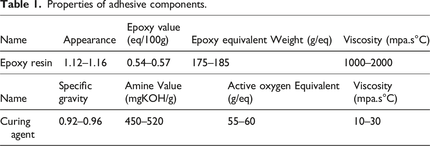
Properties of adhesive components.
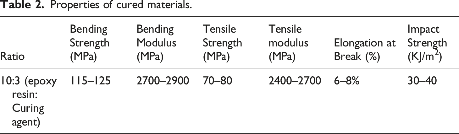
Properties of cured materials.
Fabrication of metal pin-plates
Metal pin-plates featuring single, double, triple and no rows of micro pins were fabricated using a Zhongrui Tech iSLM420DN fully automated powder circulation metal 3D printing system. The pins are cylindrical solid structures, each having a diameter of 2 mm and a height of 3 mm. The center-to-center spacing between adjacent pins is 10 mm. High-purity aluminum (A1000-AM) powder was used as the raw material, and the structures were produced using selective laser melting (SLM). The aluminum alloy specimens fabricated via 3D printing exhibit a Young’s modulus comparable to that of conventional 6061-T6 aluminum alloy, approximately in the range of 68-70 GPa. The configuration of the fabricated pin plates is shown in Figure 1. (a) The 3D printing equipment; (b) Single-row pin specimen; (c) Double-row pin specimen; (d) Triple-row pin specimen.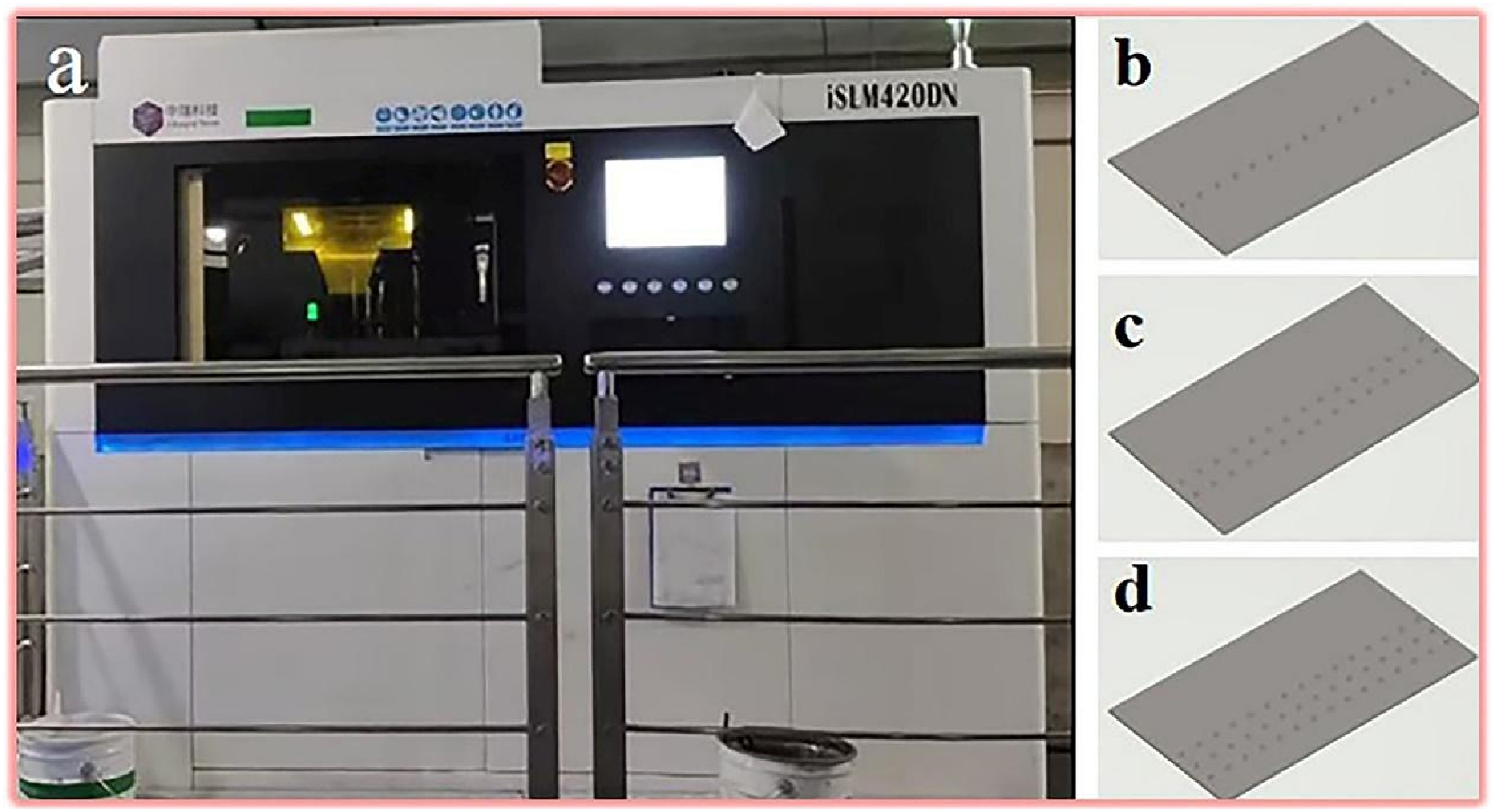
Experimental design
Experimental group Configurations.
Preparation process of the mixed joint.
Fabrication of hybrid joints
First, seven layers of carbon fiber fabric were accurately laid up on the metal pin plate, ensuring that the pins were fully embedded between the fabric layers. The assembled pin plate and carbon fiber fabric were then placed in a custom mold to form a lap shear configuration with an overlap area of 20 mm × 50 mm. The bonding area is consistent with the overlapping area, approximately 20 mm × 50 mm. As illustrated in Figure 4, the hybrid joint was fabricated using the vacuum-assisted resin transfer molding (VARTM) process. After sealing the mold, the CFRP was pre-assembled with the prefabricated aluminum plate embedded with metallic pins, which were inserted into the pores of the CFRP. The assembly was then placed into the mold, and the system was evacuated to a vacuum of −0.1 MPa for 30 minutes to ensure thorough removal of entrapped air. Under continuous vacuum conditions, thoroughly mixed epoxy resin was infused into the mold. Due to the negative pressure, the resin efficiently impregnated the carbon fiber fabric, the surrounding areas of the metallic pins, and the overlap interface. Following resin infusion, the assembly was maintained under vacuum and cured at room temperature for 24 hours. A post-curing process was subsequently conducted at 80°C for 2 hours to yield the hybrid mechanical-adhesive joint specimen. Finally, the specimens were cut and machined to prepare single-lap shear test samples. Upon curing, measurements conducted via electron microscopy indicate that the adhesive layer exhibits an actual thickness of approximately 0.2 mm. Adhesive layer thickness is controlled through the combined use of jig fixtures for dimensional limitation and uniform pressure application to expel excess adhesive (Figure 3). Schematic of the experimental specimen with one rows of pins (PB1) preparation process of the mixed joint. Pin/carbon fiber laying effect.
Joint strength testing and fracture surface observation
All joint specimens were subjected to single-shear testing using a Jinan Tianchen electronic universal testing machine to evaluate their mechanical properties. The crosshead displacement rate was maintained at 5 mm/min throughout the testing process. Each experimental group underwent six repeated tests to ensure statistical reliability of the data. A schematic illustration of the tensile test setup is presented in Figure 5. Schematic diagram of the tensile machine.
During the testing process, load-displacement data were acquired in real time at a sampling frequency of 1 Hz and continuously monitored until the specimen failed completely. The lap shear strength (τ) of the joint was calculated in accordance with equation (1).
The strain (ε) of the joint was calculated using equation (2).
Following fracture, the morphology of the specimen’s fracture surface was examined using a high-resolution charge-coupled device (CCD) microscope. The failure mode—such as interfacial failure, cohesive failure, or matrix failure—was determined based on the observed morphological characteristics, enabling a systematic analysis of the failure mechanisms under various connection configurations.
Discussion
Joint strength analysis
Figure 6(a) shows the stress-strain curves of each specimen group, and Figure 6(b) summarizes the corresponding average joint strengths. The mechanical test results revealed a clear performance hierarchy: the PB1 group (single-row pins) exhibited the most superior mechanical performance, achieving an average lap shear strength of 7.54 MPa, followed by the PB3 (three-row pins) and PB2 (two-row pins) groups, with strengths of 6.52 MPa and 5.04 MPa, respectively. In stark contrast, the pure adhesive groups without pins (Groups B and BS) and the fiber-free control group (Group CF) showed significantly lower strengths, measuring only 1.01, 1.43, and 0.52 MPa, respectively. This considerable disparity confirms that a mechanical interlocking structure is essential for enhancing the load-bearing capacity of joints. In summary, the groups were ranked in descending order of average lap shear strength as follows: PB1 > PB3 > PB2 > BS > B > CF. This sequence reveals a key observation: the joint strength does not increase linearly with the number of pins but instead exhibits a distinct non-monotonic trend. This indicates that the spatial arrangement of the pins and the resulting stress distribution are more critical than the pin count. The single-row pin configuration (PB1) exhibited optimal performance, which can be attributed to its more direct load transfer path and reduced stress concentration. In contrast, multi-row pin configurations may lead to reduced efficiency and performance fluctuations owing to the potential uneven load distribution among pin rows or the induction of local bending deformation. Therefore, simply increasing the number of pins does not guarantee enhanced performance; optimizing the configuration and spatial distribution of pins is more critical for achieving high-performance connections. (a) Combined strain and stress diagram; (b) Bar chart of average strength.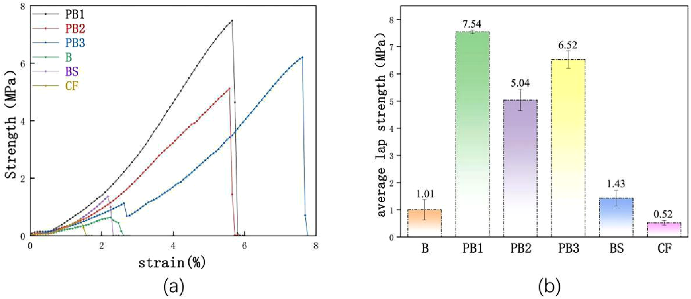
Failure mode analysis
Based on observations from digital cameras, this study systematically analyzed the fracture morphology of the joints after strength testing was performed. The typical failure modes are shown in Figure 7, where Figure 7(a)–(f) display the specific failure characteristics of each specimen group, reflecting the differences in failure mechanisms among different joint configurations. Optical images of failure mode morphologies for: (a) B, (b) PB1, (c) PB2, (d) PB3, (e) BS, (f) CF.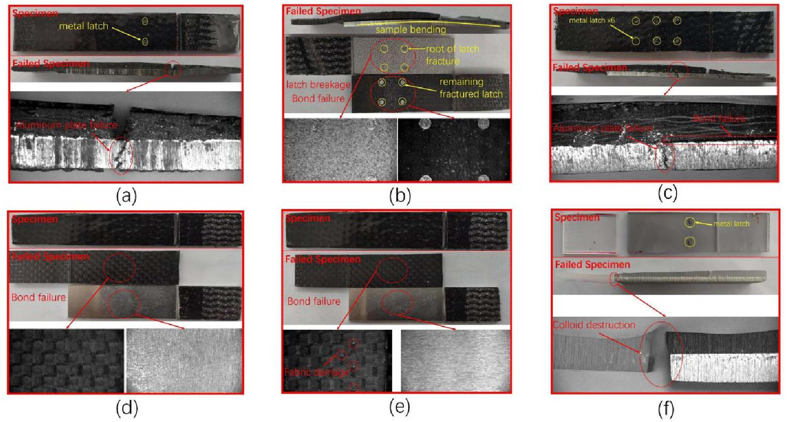
As shown in Figure 7(a), Group B (pure adhesive bonding) exhibited typical interfacial failure characteristics, where the aluminum plate and carbon fiber-reinforced polymer (CFRP) were completely separated, with no noticeable substrate damage observed in the interfacial regions. This indicates that the weak point of this joining method is the adhesive interface. In contrast, although Group BS (Figure 7(e)) also demonstrated interfacial failure, distinct resin residues and fiber tear marks were visible on the carbon fiber surface, proving that the silane coupling agent treatment effectively enhanced the interfacial bonding performance of the treated fiber.
Among the specimens incorporating mechanical interlocking structures, both Group PB1 (Figure 7(b)) and Group PB3 (Figure 7(d)) experienced fractures in the aluminum substrate, indicating that the joint strength exceeded the inherent strength of the aluminum plate, fully demonstrating the advantage of hybrid joining. Notably, although substrate failure occurred in Group PB3, it was accompanied by partial debonding of the adhesive layer, reflecting the complexity of the stress distribution in the three-row pin configuration. In contrast, Group PB2 (Figure 7(c)) primarily failed through pin fracture, accompanied by significant bending deformation, suggesting that the uneven load distribution in this configuration led to stress concentration, thereby limiting the full realization of joint performance.
Furthermore, Group CF (Figure 7(f)) exhibited typical cohesive failure within the adhesive layer, with the fracture surface completely propagating through the adhesive, indicating that the intrinsic strength of the adhesive was the limiting factor in this configuration.
A comprehensive analysis revealed a clear correlation between joint performance and failure mode: groups that experienced substrate failure (PB1 and PB3) demonstrated the best joint performance, whereas groups that failed through interfacial failure (B and BS) or pin fracture (PB2) exhibited relatively limited strength. These findings are consistent with the strength test data and elucidate the working mechanism of the hybrid mechanical-adhesive joining technique. These findings provide important guidance for the optimal design of high-performance joints: the stress distribution should be optimized through a rational pin arrangement to avoid local stress concentration and ensure effective load transfer.
Influence of pin row number on joint performance
As shown in Figure 8(a) and the failure mode analysis, the joint strength did not follow the anticipated linearly increasing trend with the number of pin rows. The lap shear strength ranking was as follows: PB1 > PB3 > PB2 > B (Figure 8(a)). Meanwhile, the fracture elongation shows an approximately linear increase with the number of pin rows (Figure 8(b)). Although the lap shear strength of PB3 was lower than that of PB1, its fracture elongation was significantly improved, indicating that increasing the number of pin rows effectively enhanced the joint toughness. (a) Comparative tensile strength; (b) Comparative elongation performance.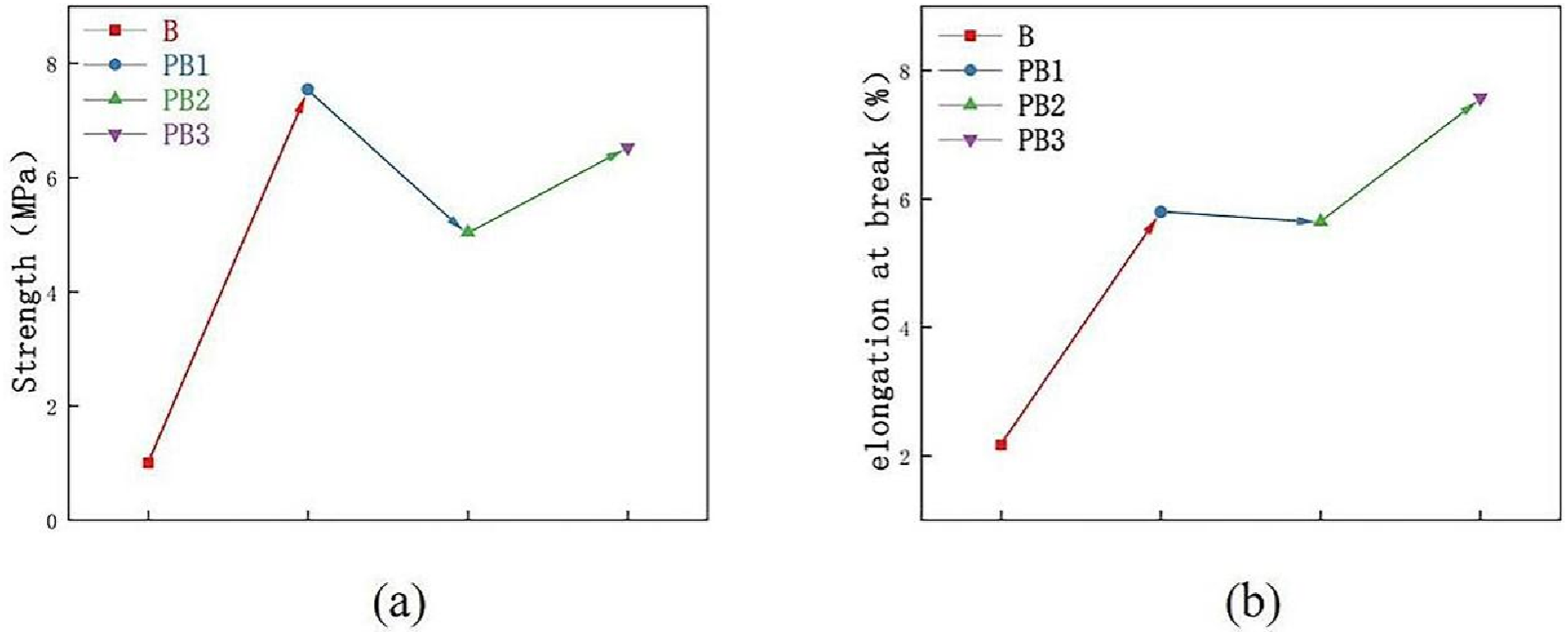
In situ observations during tensile testing revealed distinct deformation behaviors. The PB1 specimens exhibited minimal deformation before failure, which is characteristic of brittle fractures. The PB2 specimens exhibited outward bending of the metal layer, leading to progressive interfacial failure from the edges and eventual pin fracture (Figure 9(a)). The PB3 specimens, while also displaying metal layer bending, demonstrated bilateral deformation and ultimately failed owing to substrate fracture near the bottom row of the pins (Figure 9(b)). Schematic illustrations of the tensile testing process for (a) PB2 and (b) PB3.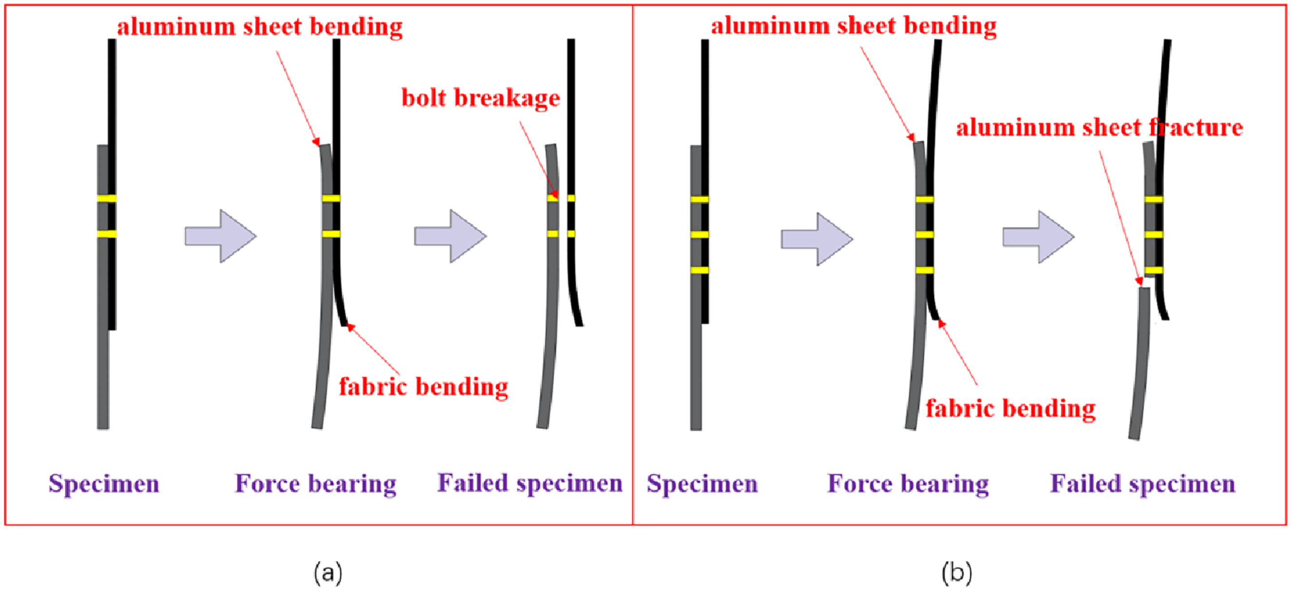
These phenomena can be explained by the “bridging effect,” which has been extensively studied in Zpin reinforcement technology. Pingkarawat et al.43,44 demonstrated through double cantilever beam tests that Z-pins enhance delamination toughness through elastic deformation, interfacial debonding, and pull-out mechanisms, which consume strain energy and create a bridging zone ahead of the crack tip that generates traction forces, as shown in Figure 10. In this study, the multiple pin rows in the PB2 and PB3 groups established a similar bridging mechanism. However, owing to the larger volume and higher load-bearing capacity of the metal pins compared those with of Z-pins, the resulting traction forces induce bending deformation in the metal layer, consequently reducing the joint strength. Among these, PB3 exhibited a stronger bridging effect than PB2, resulting in better strength performance, although it was still inferior to PB1, which lacked significant bridging. In conclusion, within the range of 1-3 pin rows, increasing the number of pin rows does not significantly enhance the joint strength but effectively improves toughness. Schematic diagram of failure of the Z-shaped pin by bonding and pulling out the extended crack.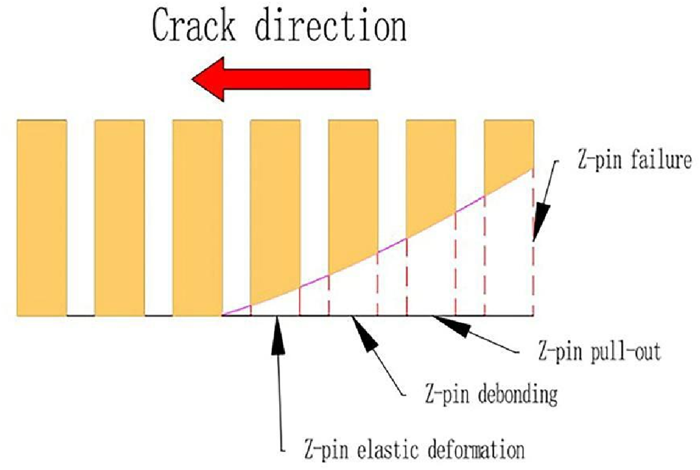
Performance comparison with other joining techniques
Lap shear strength of different joining methods.
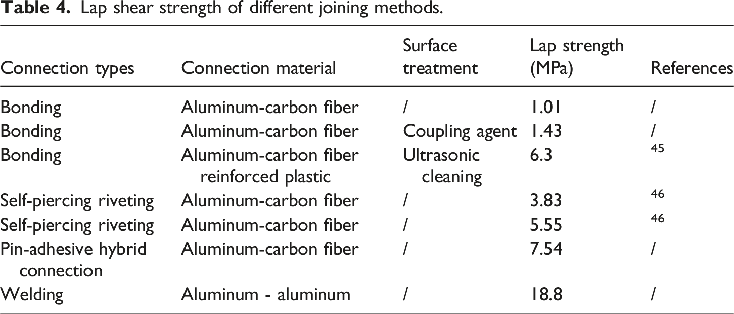
Currently, SPR is a widely used mechanical fastening technique that offers an ultimate lap shear strength of 3.83 MPa for aluminum–CFRP connections. Wang et al. 45 proposed a PC-SPR process for joining CFRP and aluminum alloy, which can increase the shear strength of lap joints to 5.55 MPa. In contrast, the bonded-pin hybrid technique developed in this study achieved a maximum joint strength of 7.54 MPa, representing an improvement of 97.2% over the conventional SPR and 35.9% over the PC-SPR process. In terms of surface treatment for enhanced joint performance, Zhang et al. 46 constructed a hierarchical porous structure on an aluminum substrate through anodic oxidation at different temperatures, combined with polishing and resin transfer molding treatment of the CFRP, ultimately achieving a lap shear strength of 23.4 MPa, which is a 268.9% increase over the untreated group. This result confirms that surface modification can significantly improve the adhesive performance. In the present study, the strength of the untreated group without pins (Label B) was 1.01 MPa, whereas that of the silane-coupled group (Label BS) reached 1.43 MPa, corresponding to an increase of 42.1%. Notably, with the application of the bonded-pin hybrid technique, the joint strength increased significantly to 7.54 MPa, reflecting a 650.2% improvement compared to Group B. This demonstrates that the contribution of mechanical anchoring far exceeds that of surface treatment alone.
In summary, without relying on complex surface treatments, the proposed bonded-pin hybrid joining technique exhibited superior performance compared with conventional riveting and some modified adhesive methods, indicating its promising potential for engineering applications. A performance comparison of the various joining methods is shown in Figure 11. Comparative lap shear performance of different joint types.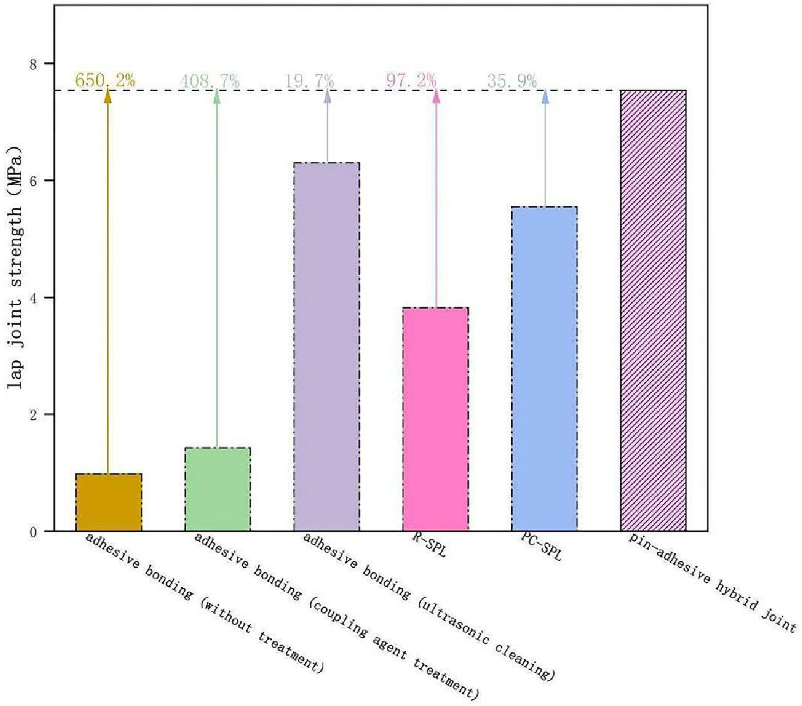
Practicality assessment the connection module
The bonded-pin hybrid joining technique can be utilized as a “prefabricated connection module” in practical applications. The core design concept involves using the non-bonded edge of the pin-integrated aluminum plate as a welding interface for integration with other metal components after completing the bonded-pin hybrid joint, thereby enabling the efficient assembly of the overall structure (Figure 12). Compared with traditional joining methods, this modular design demonstrates significant engineering advantages: the connection modules can be prefabricated and stored, and then directly deployed during actual assembly to rapidly achieve reliable connections between CFRP and metal components. This approach not only ensures connection quality but also substantially improves the assembly efficiency. Schematic diagram of overall welding.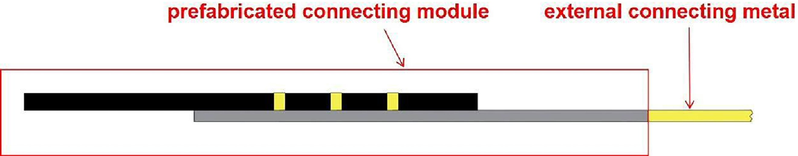
To validate the practical effectiveness of this hybrid connection module within an integrated structure, aluminum-aluminum welding comparative experiments (Label W) were conducted, as shown in Figure 6. The experimental results indicate that the average lap shear strength of the welded joint reaches 18.8 MPa, representing an increase of approximately 249.3% compared to the 7.54 MPa observed in the adhesive-pin hybrid joint, thereby demonstrating a significant enhancement in mechanical performance. This significant difference clearly indicates that, under the current design, the bonded-pin joint area remains a relatively weak link in the overall connection chain, with considerable room for performance improvement.
Based on these findings, the following optimizations are recommended: first, optimizing the spatial arrangement of pins through asymmetric or inclined configurations to improve stress distribution and reduce local bending moment concentration; second, combining mechanical joining with surface treatment technologies to achieve synergistic enhancement through interfacial modification; finally, a systematic investigation of fatigue performance and long-term durability under dynamic loading conditions to comprehensively evaluate the engineering applicability of this connection module. Through these multidimensional improvements, the comprehensive performance and engineering application value of this joining technology are expected to be enhanced.
Conclusion
This study proposes and validates a hybrid bonded-pin technique that utilizes 3D-printed metal pins to enhance the joints between CFRP and aluminum alloys. The systematic experimental investigation yielded the following conclusions:
In comparison with conventional adhesive bonding and riveting, the key advantage of this bonding process lies in integrating the mechanical reinforcement unit (i.e., the pin) with the molding of CFRP. As a result, the joint exhibits a dual bonding mechanism: adhesive bonding coupled with mechanical interlocking. Specifically, the resin layer provides interfacial adhesive strength, while the metallic conical pin bears shear loads. These two components work synergistically to enhance the joint’s damage resistance. The process retains the merits of adhesive bonding, such as absence of stress concentration and process simplicity, while compensating for the low strength of resin adhesion through the mechanical interlocking of metallic pins. Simultaneously, it avoids fiber damage to CFRP typically induced by traditional mechanical fastening methods, thereby achieving high-strength and low-damage bonding of dissimilar materials.
The single-pin-row configuration achieved an average lap shear strength of 7.54 MPa, representing increases of 650.2% over pure adhesive joints and 408.7% over surface-treated adhesive joints. Compared with self-piercing riveting technologies, strength improvements of 97.2% (conventional) and 35.9% (post-curing) were observed.
The joint performance exhibits a nonlinear dependence on the pin rows. The strength followed the order of 1-row > 3-row > 2-row, which was attributed to the bridging effect and local bending in the multi-row configurations. Meanwhile, the fracture elongation increased with the number of pin rows, indicating an enhanced energy absorption capacity.
Failure modes transition from interfacial failure in pure adhesive joints to substrate failure or pin fracture in hybrid ones. The prevalence of aluminum substrate failure in the 1-row and 3-row configurations confirmed that the joint strength exceeded the base material capacity.
The technology demonstrates modular implementation potential, where the pin-aluminum component can be directly welded to other metal structures, facilitating the integrated manufacturing of multi-material systems.
The present experiment did not involve comprehensive pretreatment procedures for the CFRP and aluminum alloy plates, leaving considerable room for enhancement. Improvements may include applying anodic oxidation to the aluminum alloy in advance, abrading the overlapping area of CFRP prior to bonding, and polishing the overlapping zone bidirectionally at a 45°angle using 120-grit sandpaper. Such measures would increase surface roughness, enhance adhesion at the bonding interface, eliminate the influence of the smooth surface layer formed after prepreg curing, and consequently improve the connection strength of the hybrid joint.
Supplemental material
Supplemental Material - The performance and influence mechanism of lap joints in carbon fiber reinforced polymer plastic/aluminum alloy hybrid structures reinforced by 3D-printed pins and adhesive bonding
Supplemental Material for The performance and influence mechanism of lap joints in carbon fiber reinforced polymer plastic/aluminum alloy hybrid structures reinforced by 3D-printed pins and adhesive bonding by Yongsheng Su, Zaien Wu, Fangtao Ruan, Huajun Feng, Yajie Sun in Journal of Thermoplastic Composite Materials
Footnotes
Author contributions
Yongsheng Su: Writing-review & editing, Validation, Supervision, Funding acquisition. Zaien Wu: Writing-original draft, Validation, Software, Methodology, Investigation, Formal analysis, Data curation, Conceptualization. Fangtao Ruan: Writing – review & editing, Supervision. Huajun Feng and Yajie Sun: Conduct of partial experiments and data analysis.
Funding
The authors disclosed receipt of the following financial support for the research, authorship, and/or publication of this article: This work is supported by the Open Research Project of Anhui Provincial Key Laboratory of Intelligent Car Wire-controlled Chassis System (QCKJJ202503), Research and application of key technologies for 3D design and manufacturing of automotive parts (HX-2025-07-031), the Key Research and Development Plan of Anhui Province (2022a05020006), Research and application of key technologies for automotive parts manufacturing execution system (HX-2025-05-034), New era education quality project of Anhui Province (2024shsjsfkc020), Undergraduate Teaching Quality Improvement Program Project of Anhui Polytechnic University (2023xmskk12, 2025xqhz01), Graduate Quality Engineering Program of Anhui Polytechnic University (2023yzl015), and Training program of innovation and entrepreneurship for college students of National level and Anhui Province (202410363012).
Data Availability Statement
Data will be made available on request.
Supplemental material
Supplemental material for this article is available online.