
Abstract
This review comprehensively explores the mechanical and microstructural properties of polymer gears fabricated using Fused Deposition Modeling (FDM), a widely used additive manufacturing technique. The paper discusses various thermoplastic polymers including PLA, ABS, PETG, Nylon, POM, and PEEK as well as their reinforced and composite counterparts. Emphasis is placed on how printing parameters (e.g., raster angle, infill density, temperature, and layer height etc.) influence gear performance, wear resistance, and dimensional accuracy. Recent advances in fiber and particle-reinforced composites, including biochar, carbon fiber, glass fiber, and metal-filled polymers, are critically examined to assess their potential for enhancing the strength, fatigue life, and thermal behavior of FDM-printed gears. Manufacturing methods such as injection molding and machining are also compared with FDM to evaluate gear accuracy and load-bearing capacity. The review identifies key challenges including moisture absorption, warpage, and print anisotropy, service temperature and highlights the importance of post-processing treatments and hybrid material strategies. By consolidating findings across recent experimental studies, this article provides insights for material selection, parameter optimization, and future research directions for developing durable, high-performance polymer gears for power transmission applications.
Keywords
Introduction
Additive Manufacturing (AM), commonly known as 3D printing, is a technique used to produce three-dimensional objects by depositing material layer by layer. The appeal of AM lies in its design flexibility, lower material waste, and faster production cycles. 1 Its capacity to fabricate intricate structures and tailor-made products efficiently has led to its widespread adoption. 2 Today, AM is being actively implemented across numerous fields such as aerospace, automotive, construction, healthcare, pharmaceuticals, and sports. 3
Gears are essential mechanical elements in power transmission systems. 4 Several Additive Manufacturing (AM) techniques are widely employed to produce gears of various sizes and geometries using materials such as plastics, metals, ceramics, and composites. Common AM methods include Stereolithography (SLA), which uses liquid resins; Fused Deposition Modelling (FDM) or Fused Filament Fabrication (FFF), which are solid filament-based processes; and Selective Laser Sintering (SLS), which relies on powdered materials. In this study, Fused Deposition Modeling (FDM) and Fused Filament Fabrication (FFF) refer to the same material-extrusion additive manufacturing technique; to maintain clarity and uniformity, FDM is adopted as the standard terminology throughout the manuscript. A growing trend in gear production is the replacement of metal gears with plastic alternatives, driven by advances in materials and manufacturing processes. In specific sectors like automotive and aerospace, polymer gears offer distinct benefits over their metallic counterparts. These include lower production costs, reduced weight and inertia, higher efficiency, quieter operation, shock and vibration absorption due to elastic compliance, and the ability to function with minimal or no lubrication. 5
FDM is favored for its simplicity, cost-effectiveness, and reliable accuracy in prototyping. During the process, a filament made of thermoplastic is heated and extruded through the printer’s nozzle, then deposited layer by layer onto a heated build platform to form the desired object. 6 According to existing research, extensive efforts have been made to improve the mechanical strength and overall quality of FDM-produced parts by refining several key process parameters. Proper process parameters optimization is essential to produce high-quality components with minimal defects.3,7
This article aims to present a thorough literature review on the mechanical and microstructural properties of parts manufactured using 3D printing via FDM of various polymers. The polymer composite (virgin polymer + additives/reinforcements) filaments are also included in the scope of this work. The focus is on effect of process parameters, description of processing challenges, limitations, and future trends. Also, provides a comprehensive guide for engineers and designers to select the appropriate materials for their specific applications based on the material behaviour under various loading conditions. Research gaps and areas of future research are also suggested for current researchers. The effect of process parameters, defects and failure mechanisms are also discussed along with their mitigation techniques.
The Figure 1 shows a structured overview of the key aspects involved in the design and analysis of polymer gears. It highlights three main areas: Polymer Materials (including thermoplastics, composites, metal-infused polymers, and blends), Gear Tooth Profile, and Manufacturing Methods (injection moulding, FDM, and machining). It also outlines detailed Performance Analysis components such as stress, fatigue, wear, thermal, and lubrication analysis, as well as finite element methods and gear life prediction. The diagram serves as a roadmap for understanding the interdisciplinary factors affecting polymer gear performance. Overview of key factors in polymer gear development.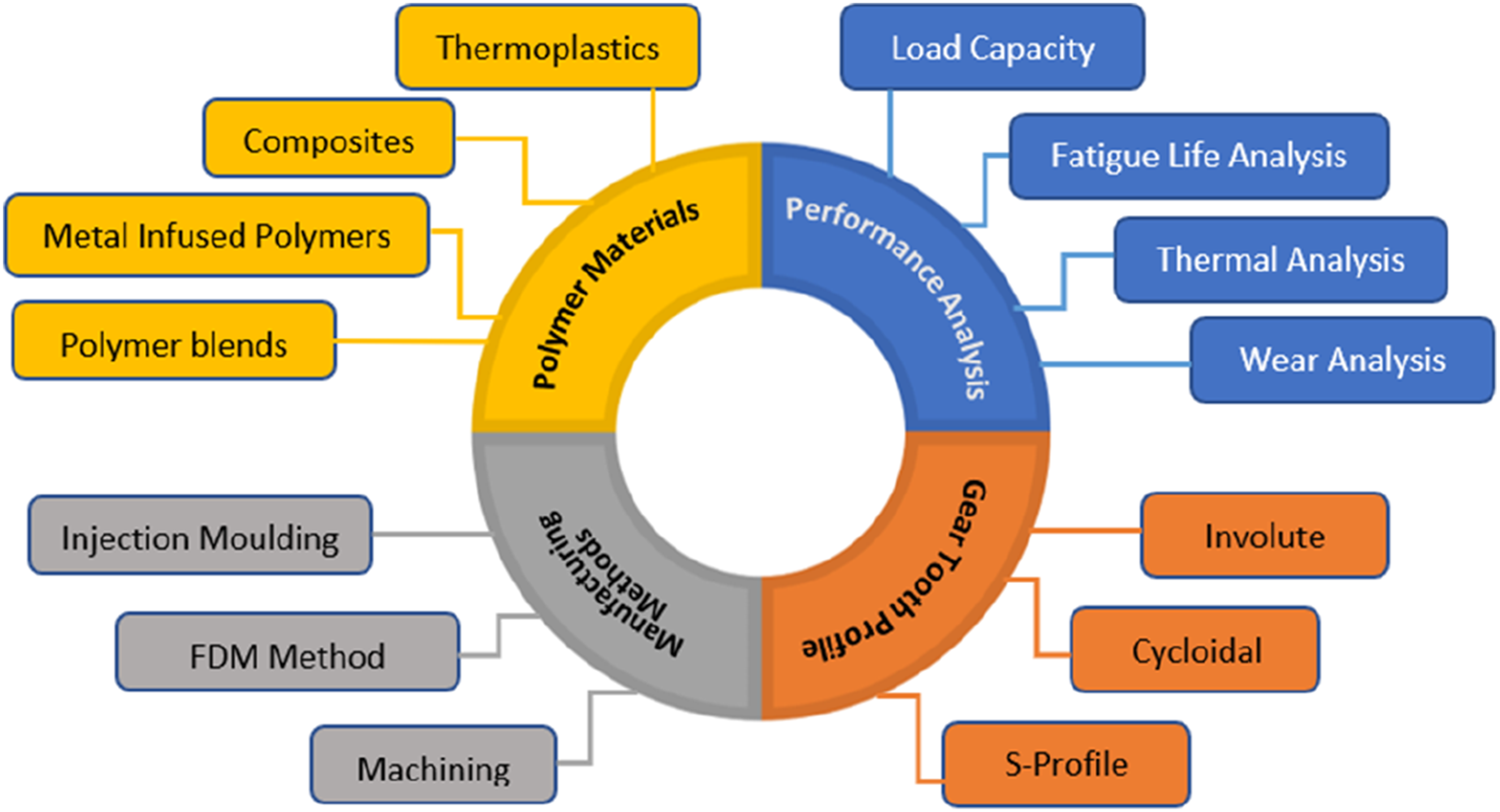
Polymer materials for gears
Thermoplastics
The materials used are classified as plastomers, specifically thermoplastics, which become soft and workable when heated above their processing temperature. This thermal behavior allows the material to be shaped while in a pliable state and then solidified upon cooling. Thermoplastics can exhibit different molecular structures: they may be amorphous, featuring a random arrangement of polymer chains or semi-crystalline, where some degree of molecular alignment exists. The selection of materials for fabricating test gears was based on their suitability for the intended functional applications. 8
PLA
Polylactic acid (PLA) is a thermoplastic polymer derived from renewable sources such as corn starch and sugarcane. Despite being relatively brittle and having lower mechanical strength compared to other engineering plastics, PLA is among the most commonly used materials in 3D printing because of its good printability and decent dimensional accuracy6,9 As a biodegradable, recyclable, and compostable material, PLA has gained attention in various industries.5,10,11 In comparison with nylon-based filaments, PLA provides improved dimensional stability, reduced thermal contraction, and lower sensitivity to moisture during FDM fabrication, leading to more accurate and repeatable gear tooth geometries. PLA can be processed without pre-drying and retains stable mechanical behavior under normal ambient conditions, whereas the hygroscopic nature of nylon often results in moisture-induced porosity, warpage, and weakened interlayer bonding. While nylon exhibits superior toughness, fatigue endurance, and resistance to elevated temperatures, PLA is better suited for low load polymer gear applications that prioritize geometric accuracy, manufacturing simplicity, and process reliability. 12 However, its mechanical properties are influenced by extrusion temperature; higher temperatures (up to around 220°C) can improve strength, although they may also introduce dimensional inconsistencies due to increased fluidity. 7 PLA gears provide moderate load-carrying capacity but suffer from low ductility, making them prone to brittle tooth-root fracture. Elevated friction levels contribute to increased wear, and limited heat resistance further constrains their application, confining PLA gears to low-load or prototyping purposes. 13
Polyamides (PA, Nylon)
Polyamide (PA), commonly known as Nylon, is a strong and durable filament material used in Fused Deposition Modeling (FDM). It exhibits reduced moisture absorption compared to earlier formulations, although it still retains some hygroscopic characteristics that can impact its mechanical performance if not properly stored.14,15 Nylon is highly regarded for its toughness, flexibility, and excellent chemical resistance, making it a preferred choice for a range of industrial applications. 16 Among various Nylon types used in FDM—such as Nylon 6 (PA6), Nylon 12 (PA12), and Nylon 66 (PA66)—Nylon 6 is particularly popular due to its suitability for producing functional parts and prototypes that require strength and resilience. 7 Specific grades like Nylon 618 and Nylon 645 have also shown strong performance, with Nylon 618 outperforming PA66 produced via injection molding under low to medium torque conditions.17,18 To ensure optimal results, especially in minimizing warping and ensuring good layer adhesion, it is essential to configure printing parameters according to the equipment manufacturer’s guidelines. 14 PA6 demonstrates strong potential for FDM-based polymer gears owing to its excellent tribological performance, high fatigue endurance, and impact toughness, although moisture absorption and directional shrinkage effects must be addressed in gear design.5,18
Polyacetal (POM, Delrin)
Delrin 100 NC010, a commercially available grade of POM-H (polyoxymethylene homopolymer), is a high-viscosity acetal material commonly used in power transmission applications due to its excellent wear resistance and high fatigue strength. 19 This thermoplastic is particularly valued in the production of polymer gears where mechanical durability is essential. However, POM materials, especially the homopolymer type, are prone to geometric instability. As a result, achieving precise dimensional accuracy requires careful control throughout the injection molding process. 20
Polycarbonate (PC)
Polycarbonate (PC), while possessing excellent thermal stability, mechanical strength, and optical clarity, is not frequently used in Fused Deposition Modeling (FDM). Despite its desirable properties, the application of PC in 3D printing is limited due to several challenges, including high melt viscosity, low surface hardness, notch sensitivity, and limited chemical functionality. Additionally, its strong hydrophobic nature further restricts its usability in certain environments and gear applications. 7
Polyoxymethylene (POM)
Polyoxymethylene (POM), also referred to as acetal, polyacetal, or polyformaldehyde, is an engineering thermoplastic valued for its high stiffness, hardness, low friction, dimensional stability, and strong chemical resistance to fuels and solvents. It is commonly utilized in injection molding, extrusion, and machining processes due to these favorable properties.21,22 However, the use of POM in additive manufacturing via Fused Deposition Modeling (FDM) faces significant challenges. These mainly stem from the material’s tendency to shrink during solidification, combined with its low coefficient of friction, which results in poor adhesion to the build platform, leading to issues such as delamination and warping. 21 Its semi-crystalline structure and excellent wear resistance further contribute to its broad industrial applications. Careful control of printing parameters, such as extrusion temperature and cooling rates, is necessary to minimize warping and achieve accurate tooth profiles in additive manufacturing.
Polyetheretherketone (PEEK)
Polyetheretherketone (PEEK) is a high-performance, semi-crystalline thermoplastic widely recognized for its exceptional mechanical strength, wear resistance, chemical stability, and ability to retain dimensional accuracy at elevated temperatures. With a continuous service temperature capability of up to approximately 260°C, PEEK is well suited for demanding gear applications in harsh thermal and chemical environments. 8 However, high-strength plastics such as PEEK are more prone to damage types like pitting and tooth fracture on gear flanks. 23 Despite these advantages, the Fused Deposition Modeling (FDM) of PEEK presents challenges due to its high melting temperature and viscosity, necessitating elevated processing temperatures (nozzle temperatures between 350 and 440°C, bed temperatures of 100–150°C, and chamber temperatures of 90–160°C). Additionally, PEEK’s rapid crystallization during printing induces thermal stresses, often resulting in warping, poor interlayer adhesion, and thermal cracking of the printed parts.24,25 The mechanical performance and fracture behavior of 3D-printed PEEK and its composites are strongly influenced by processing conditions and defects such as porosity and cracks. Careful optimization of parameters like nozzle temperature, extrusion angle, polymer viscosity, and crystallinity can significantly enhance the fracture resistance and overall quality of PEEK-based components. 26 Although FDM processing of PEEK is challenging, optimized printing conditions enable the fabrication of gears with superior strength and long-term reliability for power-transmission applications.
Acrylonitrile Butadiene Styrene (ABS)
ABS is a widely used polymer in consumer products due to its affordability and availability. Compared to PEEK, both Polyetherimide (PEI) and ABS exhibit lower resistance to abrasive wear, with ABS showing the poorest wear resistance among them. 8 The superior wear resistance of ABS gears compared to PLA can be attributed to the ductile and tough nature of ABS, arising from its rubber-modified amorphous polymer structure in which butadiene phase enhances energy dissipation and crack resistance during sliding contact, thereby reducing material removal. Conversely, the relatively brittle behavior of PLA promotes micro-crack formation and surface fragmentation under repeated contact stresses. Additionally, improved interlayer bonding and plastic deformation capability in FDM-printed ABS contribute to lower wear rates and enhanced surface durability, better thermal stability.27,28 As a petroleum-derived material, ABS is more challenging to produce than PLA but offers greater strength.9,29 ABS filaments, such as those produced by Stratasys®, are known for their high rigidity, good impact resistance at low temperatures, effective insulating properties, and satisfactory resistance to strain and abrasion, making ABS a preferred material for FDM applications. 7 Using ABS, PLA, and nylon polymers, Mourya et al. experimentally examined the tribological performance of textured journal bearings (TJBs) made using FDM. According to their examination of the response surface approach, PLA showed more wear resistance at particular texture settings, whereas ABS had the greatest impact on tribological response and had good wear resistance under ideal circumstances. 30 Their findings also indicate that printing parameters, specifically line width and layer thickness, have a significant impact on the wear performance of FDM-printed ABS and PLA. Over a wider processing window, ABS exhibits more stable and higher wear resistance than PLA. 31 ABS is commonly selected for moderate-speed and moderate-load gear applications where a balance between mechanical performance and manufacturability is required. Although PLA gears often exhibit better dimensional accuracy, ABS and nylon gears show superior wear and fatigue resistance under higher loads, indicating that moisture sensitivity, ductility, and interlayer bonding significantly influence performance beyond material type alone.
PETG
Polyethylene Terephthalate Glycol (PETG) is a lightweight material known for its excellent dimensional stability. 15 It surpasses both PLA and ABS in terms of strength, although it is more challenging to process compared to PLA. PETG offers greater ductility and toughness than PLA and ABS, thanks to its high elongation at break, which makes it both hard and flexible attributes that contribute to its strong wear resistance. 9 PETG is often preferred over PLA and ABS due to its superior heat resistance, durability, and UV resistance. Additionally, PETG exhibits more flexibility compared to the other two materials. 32 The high strength of both Nylon and PETG makes them suitable candidates for manufacturing robust FDM-printed gears. However, the printing process for these materials is more complex, making them less accessible for users without professional experience. 29 PETG typically melts at temperatures ranging from 230 to 250°C. 32
Polypropylene (PP)
Polypropylene (PP) filaments have gained popularity in FDM printing thanks to their favorable properties, such as excellent chemical resistance, low density, and outstanding fatigue resistance. Despite these advantages, PP also presents some challenges, including a high coefficient of friction and significant shrinkage, which can compromise dimensional stability. Additionally, it exhibits low impact resistance at subzero temperatures and a high coefficient of friction under dry shear conditions. 7 PP is generally not recommended for functional or high-load gears.
Polyethylene Terephthalate (PET)
Polyethylene terephthalate (PET) is a thermoplastic polyester known for its durability, chemical resistance, thermal stability, and cost-effectiveness. Although PET is infrequently utilized in Fused Deposition Modeling (FDM), its mechanical properties make it suitable for producing lightweight 3D models of gears primarily used for visualization and analytical purposes. 7
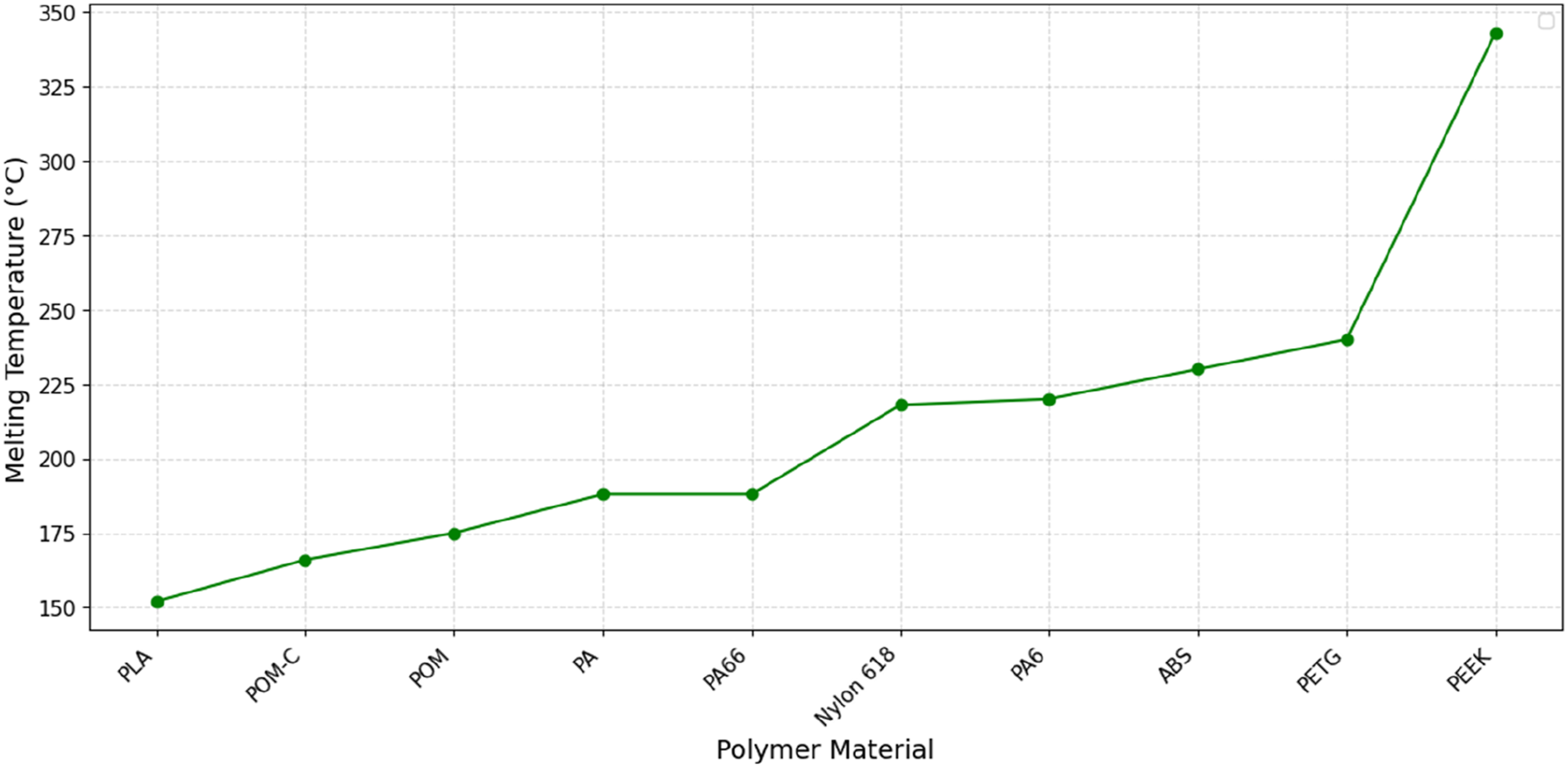
The bar chart in Figure 2 shows the tensile strength (in MPa) of various thermoplastic materials used in FDM 3D printing, particularly for polymer gear applications. PEEK has the highest tensile strength at 91.8 MPa, followed closely by PA6 (90.0 MPa) and PA66 (85.0 MPa) making them suitable for high-load gear applications. Lower tensile strength materials like PLA+TCP (29.5 MPa), ABS (30.2 MPa) may be better suited for light-duty gears or prototyping. The line graph in Figure 3 illustrates the melting temperatures of various polymer materials used in FDM 3D printing. Among the materials shown, PLA has the lowest melting point (∼152°C), making it easy to print but less suitable for high-temperature applications. As we move to engineering-grade polymers like PA (Nylon), PETG, and POM, melting temperatures rise moderately (∼170–250°C), indicating improved thermal resistance. PEEK, a high-performance thermoplastic, shows the highest melting point (∼343°C), which enables excellent mechanical properties at elevated temperatures but requires specialized high-temp printers. Tensile strength of materials across various polymer materials. Melting temperature of various polymer materials.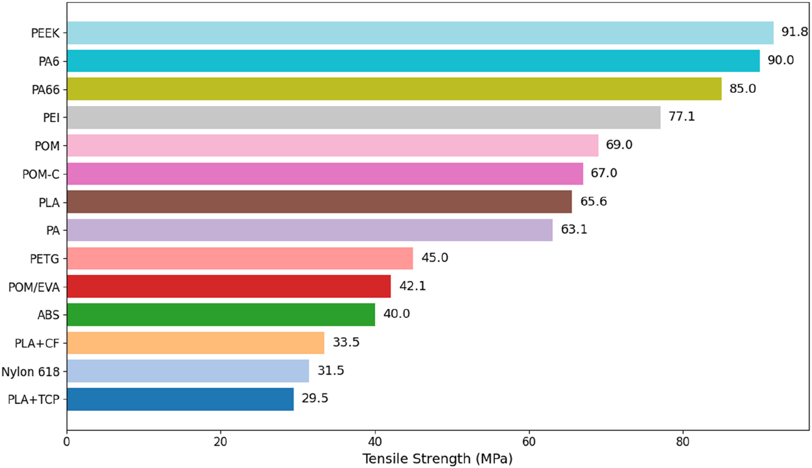
Composites
Hybrid polymer gears consist of a polymer matrix combined with a metal insert, which enhances their thermal performance, wear resistance, and overall service life. Despite their potential, there is a lack of comprehensive experimental studies addressing the behavior of hybrid polymer gears under different operational conditions. 14 To improve the mechanical properties of FDM-printed polymer parts, researchers have explored fiber reinforcement, using both synthetic and natural fibers as strengthening agents. 2 Recent advances in gear design have increasingly emphasized polymer composite gears, aiming to narrow the gap in fatigue and wear resistance between polymer and metal gears while preserving the advantages of polymer materials. The development possibilities for polymer composite gears are extensive, given the wide range of fiber and matrix material combinations available. 33 Reinforced polymer gears demonstrate superior strength-to-weight ratios and enhanced thermal stability, leading to improvements in vibration damping, resistance to cyclic fatigue, frictional contact, and wear behavior. When designing polymer-based gears, it is important to consider factors such as flexural and bending strength, ultimate tensile strength, thermal expansion and shrinkage, moisture absorption, as well as potential exposure to UV radiation and chemicals. 4
Fiber-Reinforced Polymers (FRP)
Reinforced polymers are well-suited for structural and load-bearing applications due to their high mechanical strength and thermal resistance. Short fiber-reinforced polymers enable the economical production of complex-shaped parts through injection molding. 34 For fiber-reinforced polymer composites (FRPC) to be effectively processed by additive manufacturing, several key criteria must be met: appropriate selection of reinforcement types and matrix materials, strong fiber-to-matrix adhesion, uniform fiber distribution, correct fiber alignment, robust interlayer bonding, and minimal porosity. 35 Different types of fibers offer unique benefits—glass fibers are known for their high chemical resistance, corrosion resistance, thermal stability, and tensile strength; carbon fibers provide exceptional tensile strength, low density, and excellent electrical resistivity; while aramid fibers are valued for their remarkable strength, high modulus, lightweight properties, and heat resistance. 36 Short-fiber-reinforced thermoplastic composites, which are frequently used in FDM procedures, are the main topic of this section. Since continuous and hybrid fiber reinforcement systems have different processing paths and performance outcomes than short-fiber composites, they are only briefly discussed.
Glass Fiber
Increasing the amount of glass fiber reinforcement leads to a rise in the glass transition temperature and improves interlayer bonding, though it may reduce hardness due to fiber clumping. 37 B. Mojskerc et al. studied the fatigue and wear behavior of polymer composite gears reinforced with E-glass fibers. These fibers were vacuum infused with bioepoxy resin and cured in an autoclave. Compared to carbon fiber reinforced polymers (CFRP), E-glass fibers provide advantages such as electrical insulation and superior corrosion resistance, preventing galvanic corrosion when in contact with metals. As a result, E-glass fiber composites are promising for applications in electric powertrains, chemical plants, and wastewater treatment systems. 33 However, the thermal performance of glass fiber composites can be influenced by factors such as composite composition, fiber orientation, choice of polymer matrix, and critically, the FDM processing parameters. 38 Mahdi et al. introduced a novel series of ABS-based gears reinforced with varying amounts of milled E-glass fibers. GF composites also offer better dimensional stability and reduced creep, making them suitable for moderate-to-high load and moderate-speed gear applications.
Carbon fiber
Estera V. et al. explored the fracture behavior of additively manufactured notched specimens composed of PLA and carbon fiber-reinforced PLA using a localized energy-based approach. 6 Similarly, M. Hribersek et al. produced gears using carbon-reinforced polyamide through additive manufacturing, comparing their performance to conventional polymer gears. Their study included machine-cut PA66 reinforced with 20% carbon fibers. 4 Carbon fiber has gained considerable attention due to its low weight, excellent mechanical strength, and high thermal stability across a wide temperature range. However, its non-biodegradable nature presents environmental challenges, necessitating responsible disposal practices. 38 Y. Hu et al. assessed the wear and damage characteristics of carbon fiber/polyamide filaments used in FDM printing of continuous fiber laminates, noting the formation of abrasion grooves and visible damage to the carbon fibers within the filament structure. 39 J. Galos et al. utilized a continuous carbon fiber–nylon (PA6) filament, provided by Markforged®, to evaluate the electrical conductivity of 3D-printed filaments and laminates created using FDM technology.40,41 CF-PLA gears are well suited for low-to-moderate duty applications that demand high stiffness and dimensional stability. While higher fiber fractions (≈15–20 wt%) increase rigidity and geometric accuracy, they adversely affect ductility and interlayer bonding, leading to an increased susceptibility to brittle tooth-root cracking and delamination under repeated loading. 4
Aramid fiber
K. Sandeep Varma et al. employed Aramid fiber-reinforced Polyethylene Terephthalate Glycol (PETG-KF) as the printing material using an X1E Fused Deposition Modeling (FDM) 3D printer. Their research centered on enhancing mechanical performance by carefully selecting process parameters and conducting systematic experimental evaluations. 42 The incorporation of aramid fibers enhances tooth-root strength and reduces the risk of catastrophic fracture under cyclic loading, while maintaining relatively low weight. Aramid-fiber composites enhance wear resistance and dimensional stability, making them suitable for moderate-to-high load gears, but reduced interlayer bonding and print complexity require careful optimization of fiber content and printing parameters.
Natural fiber
Natural fibre-reinforced composites are gaining increasing attention for applications in various sectors through technologies like FDM. Their thermal performance depends on several factors, including fibre type and content, chemical treatment methods, matrix material, and specific FDM processing conditions. Careful selection and optimization of these parameters can significantly enhance the thermal behavior of printed composites. A wide range of natural fibres such as kenaf, sugar palm, oil palm, pinecone, rice husk, wood dust, bamboo, sugarcane bagasse, and jute—have been successfully used in FDM research. 38 Biochar, a carbon-rich substance obtained through the pyrolysis of organic waste, has emerged as a promising additive for FDM-based 3D printing. As a renewable and environmentally friendly material, biochar offers both sustainability benefits and distinct material characteristics. Its integration into polymer composites is being explored as a means to improve eco-efficiency in additive manufacturing. In their study, P. Anerao et al. investigated the mechanical behavior of PLA-based biocomposites reinforced with varying amounts of biochar. They also analyzed how different FDM process parameters influenced the final properties of these composites. 2
Cellulose, starch, and chitosan are some of the well-known natural polymers with special properties like biodegradability, biocompatibility, and renewability, making them especially useful in replacing a petroleum-based material class. Nevertheless, it may be challenging to process natural polymers for 3D printing due to their intrinsic properties. Normally, these materials demonstrate low thermal stability and poor mechanical performance, hence making their processing quite a challenge. 43 Natural fibres like hemp, jute, flax, and bamboo have been shown to improve tensile strength, modulus, and flexural properties when incorporated into thermoplastics like PLA, ABS, and PP. 43 However, ensuring long-term durability of these materials, especially in outdoor environments, demands rigorous testing under simulated conditions including UV exposure, humidity, and temperature cycles. These insights can contribute to the development of robust composites suitable for use in infrastructure and automotive sectors. 44 Moreover, the filler loading ratio plays a crucial role in the mechanical performance of natural fibre-reinforced filaments and their 3D printability. For instance, filler content between 10 and 20% for PLA, and up to 30% for polymers like PCL and PP, has been found optimal for achieving suitable filament strength without causing nozzle clogging or defects during printing. 45 While these fibers can enhance dimensional stability and reduce material cost, their relatively lower strength, potential moisture absorption, and limited thermal resistance restrict their use in high-load or high-speed gear applications.
Metal infused polymers
Metal-filled filaments offer enhanced mechanical properties that set them apart from conventional thermoplastic filaments, in addition to providing a visually striking metallic finish. The incorporation of metal particles into the polymer matrix contributes significantly to the improved strength, rigidity, and overall durability of the printed parts. These advantages make such filaments particularly suitable for producing durable functional prototypes, small-scale industrial components, and mechanically demanding parts where longevity is essential. Despite these benefits, metal-infused filaments tend to be more abrasive compared to standard materials, which can lead to accelerated wear on printer components, especially the nozzle, due to the hardness of embedded particles. 46 G. Figueroa Romero and colleagues developed a composite material consisting of PLA and tricalcium phosphate (TCP), designed for use in additive manufacturing. This material enables the rapid fabrication of scaffolds with customized geometries, making it particularly suitable for biomedical applications. 11 M. Moradi et al. utilized FDM 3D printing to process a magnetic smart filament composed of PLA infused with iron particles. To accommodate the unique properties of this material, the printer setup was modified to enable the application of a magnetic field during the printing process. Compared to conventional PLA, this iron-filled filament exhibits a higher melting point and reduced dimensional precision. While it is more cost-effective, its abrasive nature necessitates the use of wear-resistant nozzles. 47 However, incorporating these fillers can make the material more brittle and weaken interlayer bonding during FDM printing, which may cause tooth-root fractures or delamination under repeated loading. Careful selection of filler type, concentration, and printing parameters is therefore crucial to produce reliable gears for light-to-moderate duty applications. The selection of the metal inserts was based on important factors related to gear applications, such as increased load-bearing capacity and wear resistance, improved thermal conductivity for heat dissipation, chemical and thermal compatibility with the polymer matrix, and allowable printability without excessive nozzle wear or unstable processing.
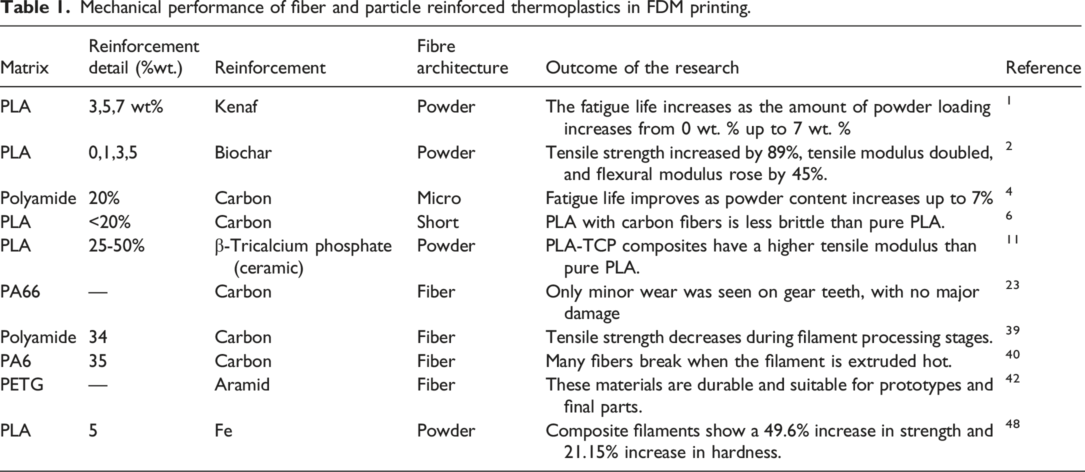
Mechanical performance of fiber and particle reinforced thermoplastics in FDM printing.
Post-processing treatments
Alexandra et al. explored the use of thermoplastic polymers including PLA, ABS, and PLA that underwent heat treatment at 75°C for 3 hours in the production of gears. The heat-treated PLA gears maintained a surface profile similar to that of untreated PLA, though a slight improvement in wear resistance was observed. 27 A.S.H. Md Yasir et al. studied the effects of thermal treatment on the mechanical properties and dimensional accuracy of carbon fiber-reinforced high-temperature PLA parts. Their tests involved heating at 70°C, 100°C, and 130°C for periods of 30, 60, and 90 minutes. However, the results did not clearly indicate a relationship between the treatment parameters and improvements in mechanical performance. 49 Similarly, M. Shbanah et al. applied heat treatment to PLA prints at 55°C, 65°C, and 80°C for 5 hours, followed by stabilization at 20°C for 15 hours. This process resulted in a 35% increase in tensile strength and reduced porosity, with no deformation detected in the test specimens. 50
Polymer blends
Polymer blending enables the combination of desirable attributes from different materials, potentially enhancing the overall performance of the final product. Polyethylene (PE), known for its affordability and broad applicability in sectors such as packaging, agriculture, and healthcare, is one of the most commonly used plastics. However, its widespread usage has led to increased plastic waste. A. Karaki et al. developed a printable blend by combining low-density polyethylene (LDPE) with expanded polystyrene (EPS) and incorporating styrene-ethylene-butylene-styrene (SEBS) rubber as a compatibilizer. Their results demonstrated that the compatibilized blends exhibited improved printability compared to the individual components. 51 Similarly, M. Galeja et al. examined the potential of blending polyoxymethylene (POM) with 2.5%, 5.0%, and 7.5% by weight of ethylene-vinyl acetate (EVA) for fused deposition modelling (FDM) applications. Although the inclusion of EVA reduced the stiffness and strength of the POM matrix, it significantly enhanced the ductility, resulting in an increase in toughness by over 50%. 22 Additionally, I. Tamasag et al. explored the effect of in-process heat treatment on the mechanical behavior of PLA during FDM printing. They applied localized hot air at 80°C during the fabrication process and observed an increase in tensile strength of up to 12.5% due to the applied thermal treatment. 52
This section reviewed the properties and challenges of various polymers and composite materials used in FDM 3D printing, highlighting common thermoplastics like PLA, Nylon, ABS, PETG, POM, and high-performance polymers such as PEEK and PEI. Reinforcement with synthetic fibers (glass, carbon, aramid) and natural fibers significantly enhances mechanical strength, thermal stability, and wear resistance, though issues like moisture absorption, warpage, and nozzle abrasion persist. Heat treatments and optimized printing parameters improve material performance, yet processing high-viscosity and natural polymers remains challenging. Despite advances in hybrid polymer-metal gears and bio-based composites, experimental data on long-term durability, environmental impacts, and process optimization under varied operational conditions remain limited. Future research should focus on developing sustainable composite filaments with enhanced printability, investigating the effects of multi-material hybridization, and establishing standardized testing for mechanical and thermal performance in real-world applications.
Gear design and analysis
Gear geometry
The involute gear profile is widely favored due to several advantages: it generates less vibration and ensures consistent axle loads because the normal force at the contact point remains nearly constant in direction and magnitude. This profile is also tolerant to small changes in gear center distance and supports the use of straight-flank cutter tools (racks). Adjusting the position of the cutter increases the tooth root thickness, enhancing bending. However, this design has some limitations, such as reduced tip thickness and a lower contact ratio.18,53 Studies on FDM-fabricated PLA, ABS, and high-performance thermoplastic gears show that involute profiles enable stable meshing, consistent load transfer, and satisfactory wear behavior. The constant pressure angle of involute gears also minimizes the effect of profile inaccuracies arising from raster deposition and interlayer bonding, making them well suited for additively manufactured polymer gears.9,54
Compared to the involute profile, the cycloidal profile offers several benefits: it provides stronger teeth due to a wider root, making it easier to produce through casting or for smaller gears. It experiences lower Hertzian contact stresses because its contact surfaces are convex–concave (epicycloid–hypocycloid), unlike the involute’s convex–convex surfaces. Additionally, cycloidal gears avoid tooth undercutting, allowing for fewer teeth and higher gear ratios. When the generating diameters are half the pitch diameter, the hypocycloid forms a straight radial line, simplifying manufacturing. 53 Cycloidal tooth geometries exhibit a higher sensitivity to dimensional deviations and printing resolution, which necessitates precise control of FDM process parameters to accurately reproduce the intended profile. Consequently, FDM-manufactured cycloidal gears are more appropriate for low-speed applications where high positional accuracy and controlled operating conditions are required.
S-gears were designed as an alternative to involute gears, particularly for applications where severe scuffing occurs on the addendum and dedendum. These modern gears feature a curved contact path, starting and ending with a forced convex–concave interaction. This convex–concave contact notably reduces the load during meshing, resulting in significantly longer gear lifespan. The continuous and smoothly varying curvature of S-gear tooth profiles lends itself well to layer-wise fabrication in FDM. Nevertheless, precise realization of the S-shaped geometry depends on sufficient printing resolution and careful optimization of raster orientation. 19 The functional behavior of polymer gears is governed by the combined effects of tooth geometry and the low stiffness, viscoelastic response, and process-induced anisotropy associated with FDM fabrication. The relatively compliant nature of polymers leads to increased tooth deformation under load, while viscoelastic characteristics influence stress evolution and wear during cyclic operation. Moreover, direction-dependent interlayer bonding controls tooth-root strength, rendering both gear geometry and build orientation critical for effective and reliable load transmission. 55 Previous studies predominantly favor involute gear profiles for additively manufactured polymer gears because of their robustness to minor geometric inaccuracies, while cycloidal and S-gear profiles are more sensitive to printing resolution and dimensional deviations. This sensitivity largely explains the limited use of non-involute profiles in FDM gear research despite their theoretical benefits.
Dimensional tolerances in FDM-manufactured polymer gears
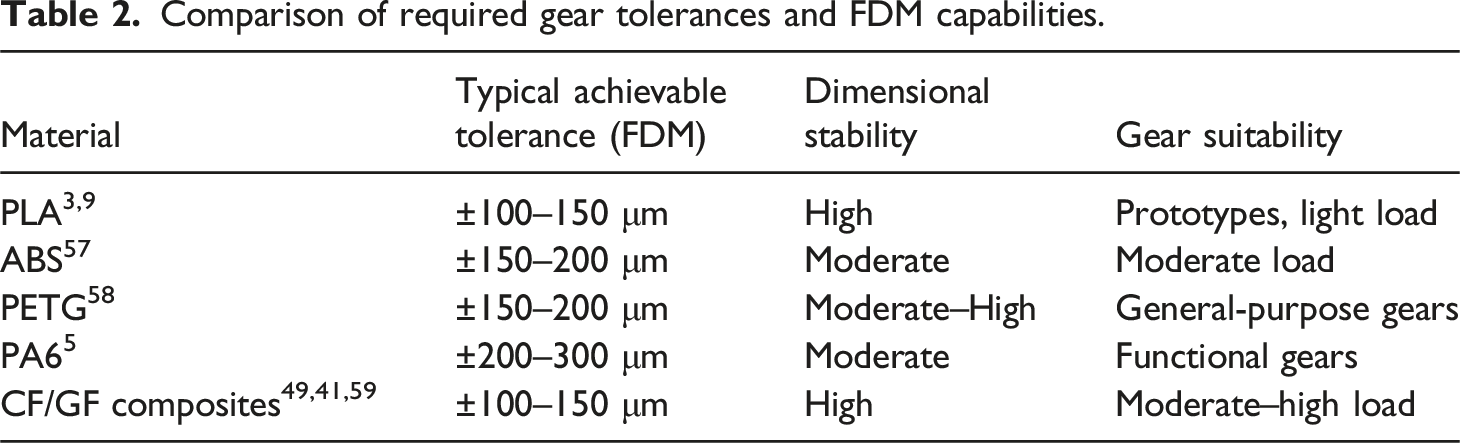
Dimensional accuracy plays a critical role in gear performance, as inaccuracies in tooth profile, pitch, and backlash directly influence load sharing, vibration, and wear behavior. Traditional polymer gears generally demand tight dimensional tolerances, typically on the order of ±20–50 μm, depending on gear module and functional requirements. In contrast, achieving this level of precision through Fused Deposition Modeling (FDM) is challenging because of the inherent layer-by-layer fabrication process, thermal contraction during cooling, and material-induced anisotropy.
In practical applications, gears produced using FDM typically exhibit dimensional accuracies on the order of ±100–300 μm, which is generally sufficient for light-to-moderate duty gear systems. Polymers including PLA, PETG, and ABS tend to provide greater dimensional consistency and more uniform tooth geometry, while nylon-based materials often show increased dimensional variation as a result of moisture sensitivity and higher shrinkage during processing. 56
Filament diameter plays a significant role in dimensional accuracy, as smaller filaments such as 1.75 mm allow more precise material flow control and improved geometric fidelity compared to 2.85 mm filaments. In addition, the use of fiber-reinforced polymers particularly those containing carbon or glass fibers can increase material stiffness and minimize thermal distortion, thereby improving the dimensional stability of FDM-printed gears. Nevertheless, high fiber loadings may degrade surface quality and weaken interlayer adhesion, which can ultimately limit the attainable accuracy of the printed components.5,49
Comparison of required gear tolerances and FDM capabilities.
Manufacturing methods
Injection molding
Polymer gears made from PA6 were manufactured using injection molding with a single-cavity mold. Their geometry was assessed using the Wenzel LH54 gear-measuring machine, and the gears were classified as quality grade Q10 according to ISO 1328. The injection pressure was maintained at 60 MPa, and the mold temperature was set to 70°C. 18 Achieving high-quality gear grades requires careful attention to the tooth profile geometry. Since material shrinkage is less pronounced at the tooth tip compared to the root, the final profile can deviate significantly from the ideal involute shape if the mold design is inadequate. The extent of shrinkage largely depends on the material and processing conditions. Furthermore, maintaining lead quality is crucial because excessive lead deviations cause uneven load distribution across the tooth face, resulting in stress concentrations. 20
P. Zengeya et al. produced HDPE gears through injection molding and found that gear tooth wear and failure were influenced by the mold temperature used during manufacturing. Gears molded at lower temperatures demonstrated better wear resistance under higher loads (3 Nm and 4 Nm) but were more prone to failure due to material flow issues compared to those molded at higher temperatures. 60 D. Schubert et al. fabricated PA66 spur gears via injection molding and studied how process design can offset mold design effects on the gears’ geometric, microstructural, mechanical, and tribological properties. 61 Most polymer gears are made from semi-crystalline materials, which solidify rapidly upon contact with the mold, often resulting in an amorphous surface layer with inferior mechanical properties. Therefore, both manufacturing accuracy and material structure significantly affect the durability and performance of polymer gears. 62
3D printing
The FDM process involves several key parameters that influence the quality of the final printed part. This section provides an overview of these FDM parameters essential for producing high-quality parts. The printing pattern defines the nozzle’s path during printing and affects the strength and surface quality of the part. Layer thickness controls how thick each printed layer is, impacting the resolution and overall strength; thicker layers generally improve bonding between layers, boosting part durability. The raster angle, or the direction of the infill pattern, plays a key role in determining mechanical properties such as tensile strength and stiffness.
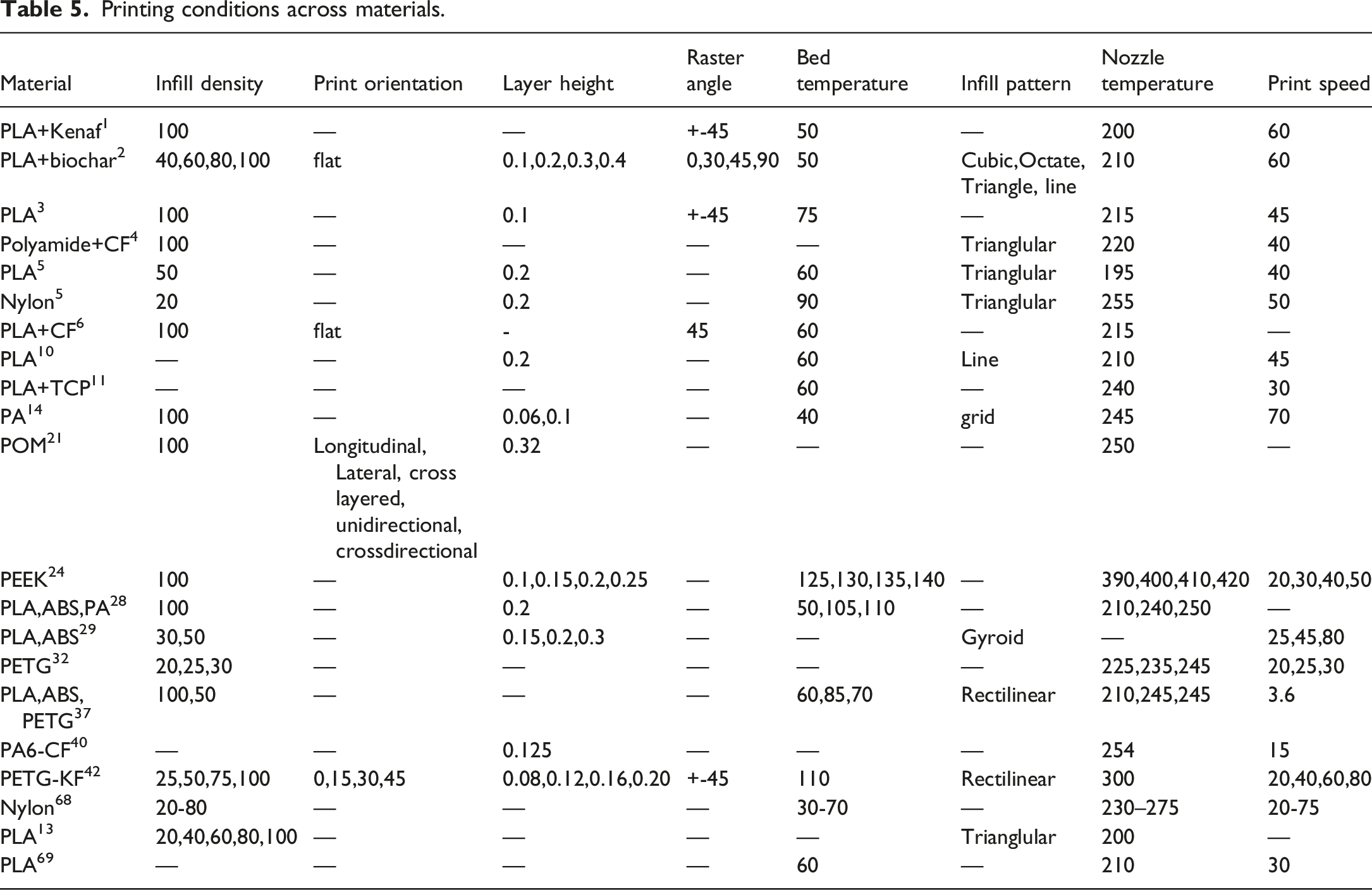
Infill density refers to how much material fills the inside of the printed object, greatly influencing its strength and weight. Higher infill density creates a denser structure, improving load transfer and overall strength during tensile testing. 2 Printing temperature controls the melted polymer’s flow and viscosity, which affects filament bonding and the strength of the final part. 3 For example, Robert Ciobanu et al. used printing temperatures of 210°C for PLA gears, 240°C for ABS gears, and 250°C for PA gears to reduce issues like stringing and oozing. 28 Orientation in 3D printing refers to how the object is positioned on the build platform relative to the printing direction. This alignment greatly affects the mechanical strength and overall quality of the print by reducing the weaknesses between layers and enhancing structural stability. Printing speed controls how fast the nozzle moves while depositing material. Although faster speeds reduce printing time, they can lower print quality by weakening layer adhesion and causing surface defects. Finding the optimal speed is essential to balance printing efficiency with part accuracy, as excessive speed can lead to poor bonding, surface flaws, and nozzle jams. 42
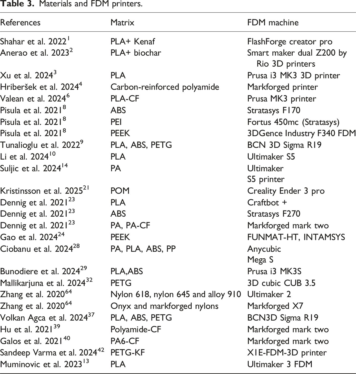
Precision temperature regulation in the print bed is critical for adequate layer adhesion in FDM printing. Fluctuations in the bed temperature can cause base layer warping, resulting in print inconsistencies and failures. 38 By optimizing process parameters according to the intended application, 3D printed parts can achieve improved strength-to-weight ratios and tailored properties. With advantages such as reduced waste and lower labor costs, 3D printing has emerged as a sustainable alternative to traditional manufacturing, as reflected in its growing global market presence and future growth projections. 63 Robert Ciobanu et al. produced 3D-printed gears using PA, PLA, ABS via FDM, and PP (photopolymer) via SLS to evaluate their wear performance. Among the tested materials photosensitive resin, PA, PLA, and ABS, the PLA gears printed through FDM demonstrated the best wear resistance. Jakub Bryla et al. created prototype spur and herringbone gears using PET-G filament through additive manufacturing. 17 Y. Zhang et al. fabricated nylon gears using various materials such as nylon 618, nylon 645, alloy 910, Onyx, and Markforged nylon, finding that nylon 618 performed better under low to medium torque conditions. For nylon 618 gears, some melting was observed on the tooth surface, but no material was lost during use. 64 The three FDM process parameters that most strongly influence polymer gear performance are layer orientation, infill density, and raster angle. Raster angle affects stress distribution and wear behavior at the gear tooth surface, infill density governs stiffness and load-carrying capacity, and layer orientation dictates interlayer bonding strength and fatigue resistance. For gear applications dominated by cyclic loading and wear, layer orientation has the most significant influence, followed by infill density and raster angle.65–67
Materials and FDM printers.
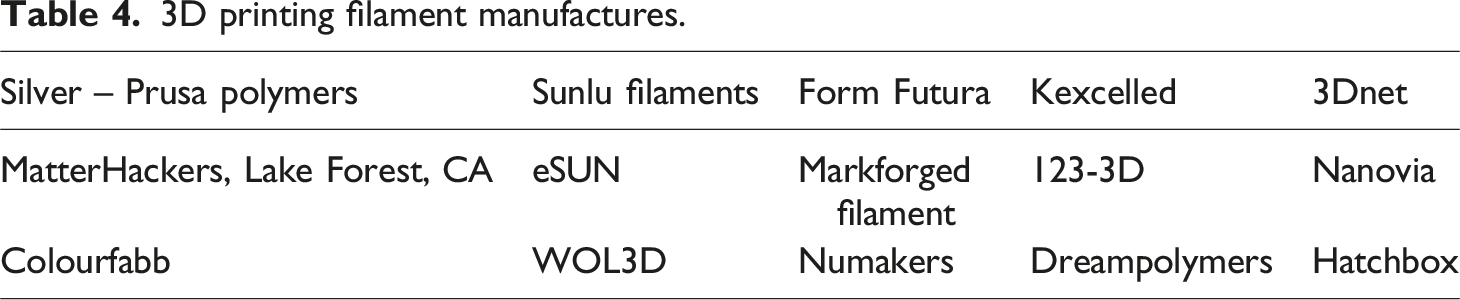
3D printing filament manufactures.
Printing conditions across materials.
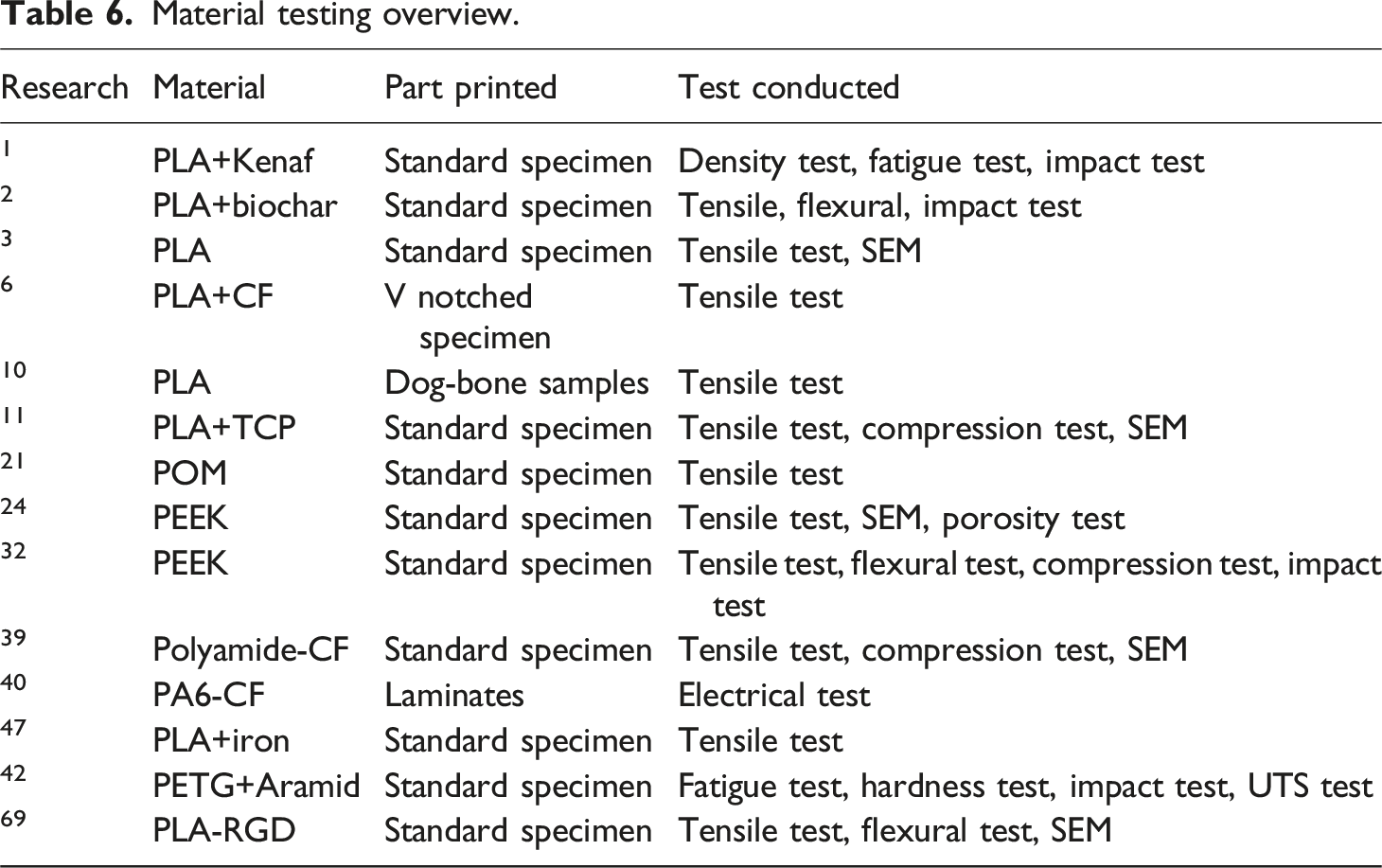
Material testing overview.
Machining
B. Mojskerc et al. machined E-glass fiber polymer composite gears from a 3.6 mm thick composite plate using a Sodick MC 430L precision milling CNC machine. The fiber orientation in the gear teeth varied according to the machining orientation of each tooth. The gear profiles were cut following the ISO 53 involute profile type A standard. 33 D. Zorko et al. produced test gears by gear hobbing from extruded bars and reported no differences in failure modes between injection-molded and machine-cut gears. They also noted that the wear rate was similar regardless of the manufacturing method, although fatigue behavior results were not provided. 70
Impact of manufacturing on gear accuracy and performance
Injection moulding method is widely used for mass production of plastic gears and provides high dimensional accuracy and surface finish. However, issues like shrinkage, internal stresses, and inconsistent material distribution can affect the mechanical properties. Gears made by injection moulding typically exhibit good repeatability and moderate fatigue resistance, but performance may degrade under high loads or temperatures unless reinforced materials are used. FDM offers flexibility and rapid prototyping but often results in lower precision and poorer surface finish compared to traditional methods. Layer-by-layer deposition can introduce anisotropy, voids, and layer adhesion issues, affecting strength, wear resistance, and noise during operation. Gear accuracy depends heavily on print parameters (e.g., infill, orientation, layer height), and post-processing or annealing may be needed to enhance performance. Despite limitations, FDM is cost-effective for low-volume production and design iterations.
Manufacturing accuracy and surface finish of FDM polymer gears.
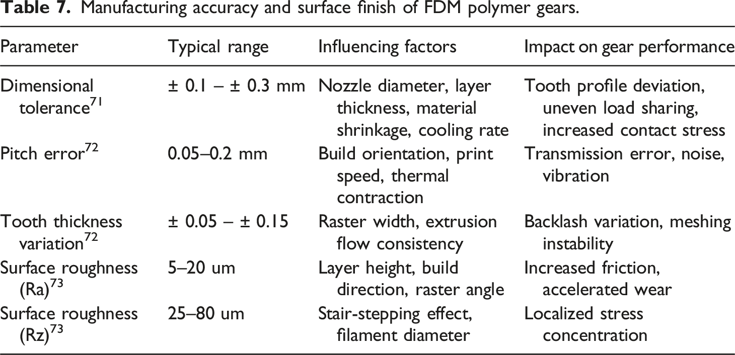
Reported dimensional tolerances and surface roughness values for FDM-manufactured gears vary considerably among studies due to differences in printer capability, material choice, and post-processing methods. This variation demonstrates that gear accuracy is influenced more by process control and finishing practices than by material properties alone.
Load capacity and stress analysis
Fatigue is recognized as the primary failure mechanism in gears due to the repetitive nature of their operation with modern systems demanding higher load capacities, longer lifespans, and improved reliability.74,75 Gears frequently function under severe or high-load conditions, leading to issues such as cracking, pitting, spalling, and surface wear. These faults can degrade power transmission efficiency, and cracks in particular can compromise the system’s performance and may lead to gear failure if left unaddressed. 76 Gear wear typically involves material loss from the working surfaces of the teeth, and damage beyond uniform wear can result in inconsistent tooth-to-tooth performance. 77 Recent studies have explored advanced techniques and strategies to improve fatigue life. 78 Traditionally, fatigue life estimations are based on stress-life (S-N) curves obtained from standardized testing, where specimens are subjected to cyclic loading to determine failure points, and the results are used to predict the fatigue life of similar gear materials. 79
Gears were tested on testing rig, presented in Figure 4. A detailed description of the test rig can be found in some of the previous works.4,70,80 The experimental setup consists of a motor equipped with a gear reducer to provide the required torque for the test. The motor is connected to a mechanical gear system comprising two parallel shafts. A steel gear and a polymer gear, manufactured using additive technology, are mounted on the respective shafts and engaged in meshing to transmit power. A pulley-type wheel is fixed on the drive shaft, around which a wire is wound. At the free end of the wire, calibrated weights are attached to apply the load. By varying the weights, precise control over the applied load is achieved. This arrangement enables the study of fatigue and wear behaviour of the polymer gear when subjected to repeated loading cycles against the steel gear. Testing rig.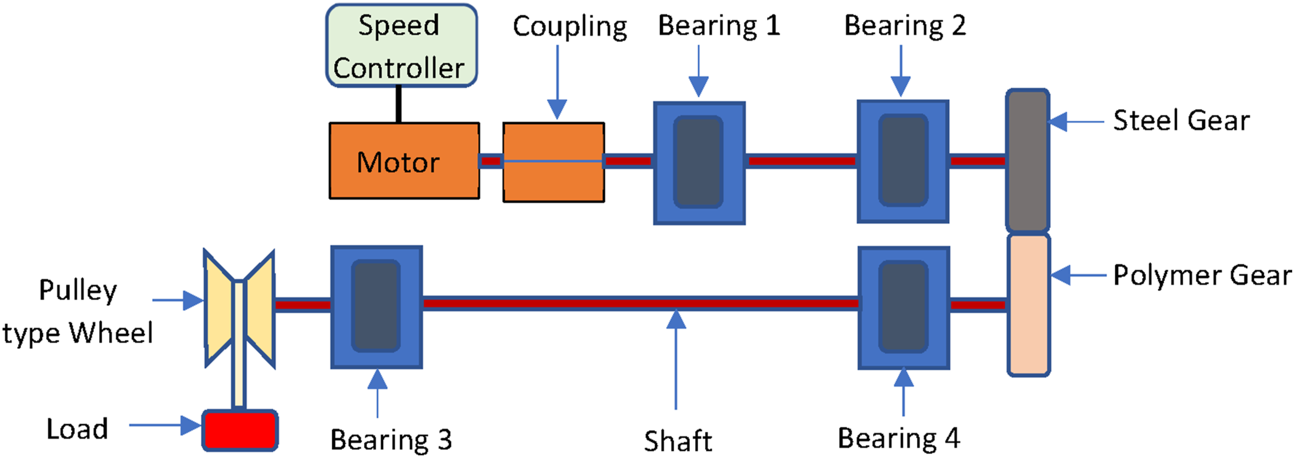
Contact fatigue life
During the service life of a gear, it is subjected to various forces, particularly contact stress, which can lead to failures such as abrasion, pitting, and spalling. Pitting and spalling are the most prevalent types of surface fatigue, with spalling often resulting in earlier and more severe secondary damage compared to pitting. 81 Thus, developing a predictive model for contact fatigue life that incorporates the effects of actual stress distribution, residual stresses, and failure mechanisms is vital for ensuring safe and reliable gear design. 82 When gears operate under high speeds and heavy loads, their tooth surfaces endure cyclic alternating loads. This often results in fatigue crack initiation slightly below the surface, typically ranging from a few to several tens of microns deep. These cracks propagate under maximum shear stress and eventually evolve into long cracks that cause fatigue-related pitting corrosion. 83 The lifespan of gears under contact fatigue conditions is primarily influenced by the contact environment and the material’s fatigue strength. The normal load (ωn) has a direct impact on contact stress and the multiaxial strain/stress conditions in the gear tooth contact zone, thereby playing a significant role in determining fatigue life. 84
To accurately evaluate the fatigue performance of polymer gears, durability tests must be carried out across various temperature conditions to gather essential fatigue data for enhancing design methodologies. However, this approach is highly time-consuming. Z. Lu et al. performed an accelerated fatigue life test on POM gears by gradually increasing the torque from 30 Nm to 70 Nm. In their study, gear failure was classified as contact fatigue failure when the pitting area covered either 10% of a single tooth’s surface or 50% of the total surface of an individual tooth. Their findings showed that all failures in the tested POM gears were due to contact fatigue. 85 Due to the complex nature of stress distribution during gear meshing, the tooth root is subjected to multiaxial stress. Under such conditions, fatigue damage is not isolated but rather results from a combination of high-cycle and low-cycle fatigue mechanisms. 56
Root fatigue life
Tooth root fatigue cracking is a frequent failure mode that significantly reduces the dynamic efficiency and operational lifespan of gear systems, ultimately compromising the mechanical stability of the equipment. T. Zhang et al. analyzed how loading conditions, gear design features, and crack parameters influence crack behavior. Their study revealed that increasing the thickness of the gear’s rim and web leads to a slower rate of crack growth. 56 L. Landi et al. investigated the bending strength of gear teeth by comparing two root profile designs circular arc and elliptical, both of which are suitable for injection molding and commonly adopted in plastic gear manufacturing. They introduced an analytical method aimed at optimizing root geometry to minimize bending stress in plastic gears. 86 R.M. da Silva et al. utilized vibration signal analysis to detect contact fatigue in gears. They introduced a failure-oriented method based on vibration monitoring, where material removal was used to simulate gear failure. Artificial damage was applied to the flank of helical gears to mimic real-world failure conditions. Failure detection was carried out using damping response assessment, impact analysis, kurtosis evaluation, and tracking of the gear meshing frequency. This approach supports condition-based maintenance strategies by allowing early fault detection, potentially extending maintenance planning windows and minimizing operational downtime. It is especially beneficial for monitoring gear systems in industrial environments to identify contact fatigue failure. 87
Stress concentration frequently develops around component notches, which can reduce fatigue resistance and eventually result in component failure. Y. Zhang et al. performed fatigue testing on notched automobile transmission gears and developed a probabilistic fatigue analysis model that incorporated the size effect. The experimental data closely aligned with the predicted P S N curves, confirming the model’s accuracy. 88 Surface pitting on the flanks of gear teeth is a frequent cause of gear failure. Enhancing the contact fatigue strength of gears is commonly achieved by developing new material combinations and applying specialized heat treatments. The contact on the driving gear or pinion tooth initiates near the root and progresses toward the tip, with slip moving away from the pinion pitch line. Conversely, contact on the driven gear or wheel tooth starts at the tip and concludes near the root. High-quality surface finishing is crucial because cracks often originate from surface defects and irregularities. 89 Tooth fracture is a common failure mode closely linked to the bending strength of gears. Among the various factors affecting gear bending fatigue life, the shape of the tooth root transition curve is particularly important, as it influences the gear’s ability to resist bending fatigue. C. Wang et al. studied how the morphology of the tooth root transition curve impacts bending stress. 90 Additionally, a method to measure cyclic crack growth during the final phase of tooth root fatigue failure has been developed. Haelie Egbert et al. used the SAE standard single tooth bending fatigue test with high-speed photography to capture moments before tooth failure and applied image processing to calculate crack length during each load cycle, allowing determination of the crack growth rate. 91
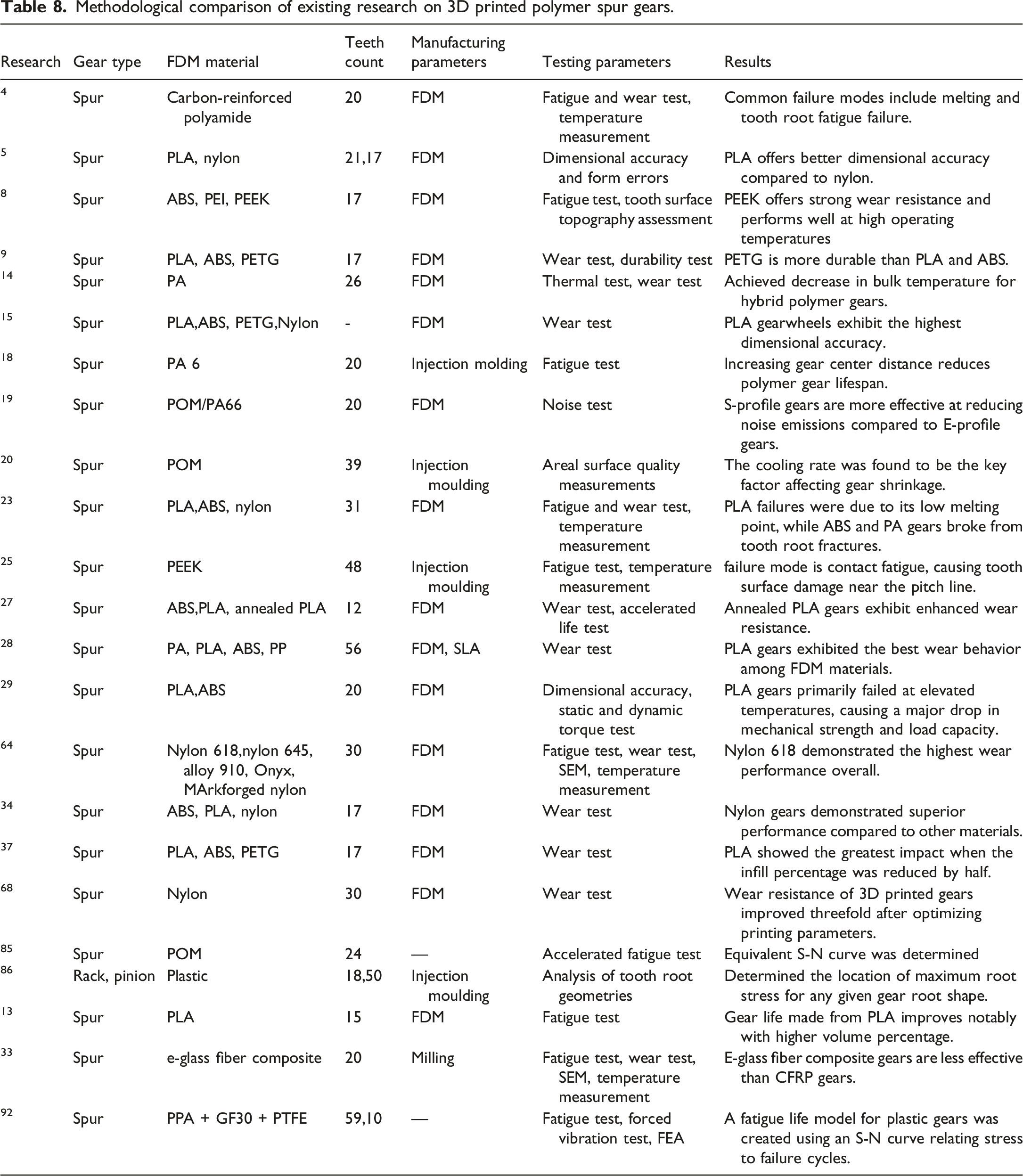
Methodological comparison of existing research on 3D printed polymer spur gears.
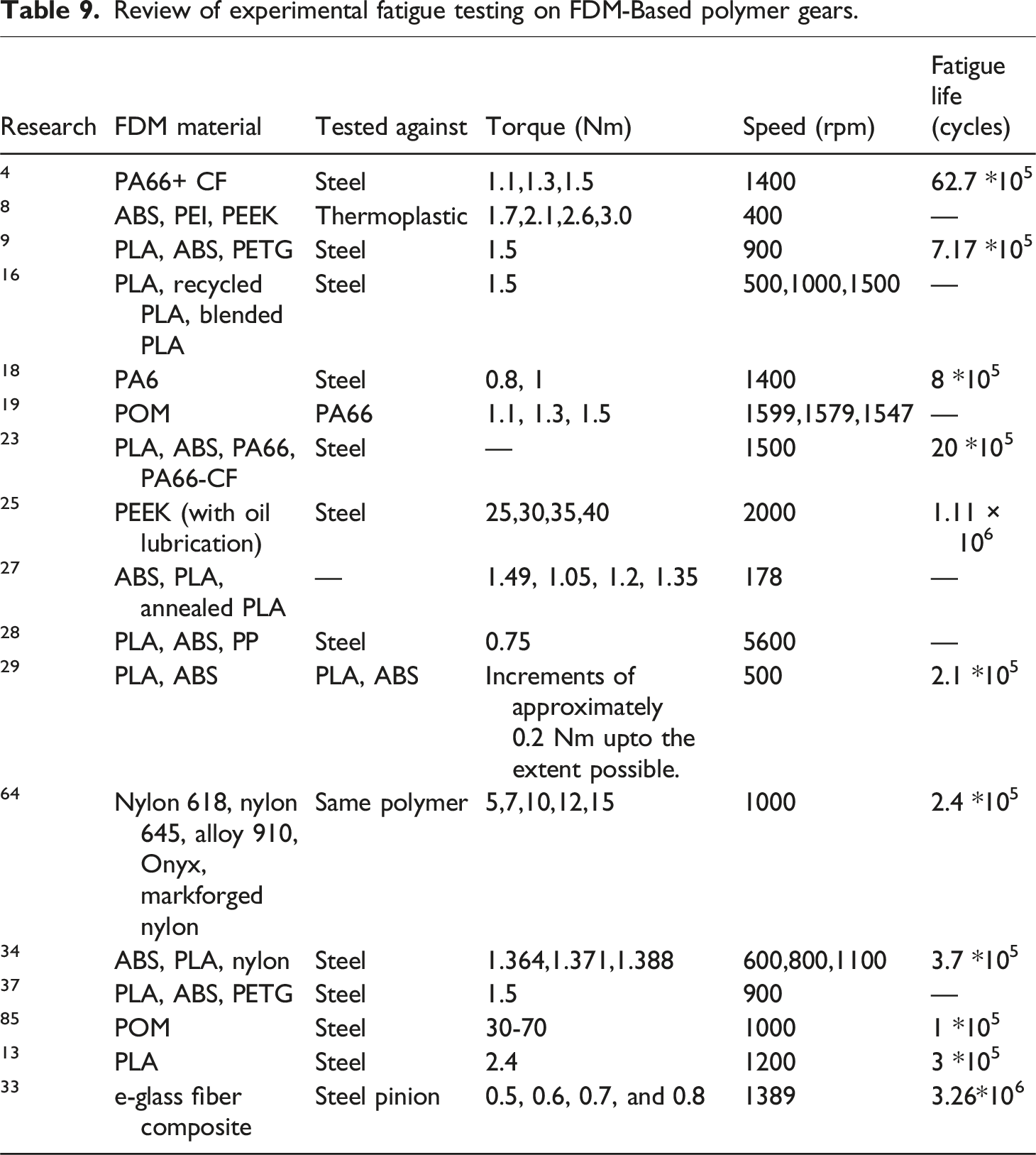
Review of experimental fatigue testing on FDM-Based polymer gears.
Wear analysis
Gear wear refers to the material loss from the tooth contact surfaces during operation. It typically progresses through three phases: an initial “running-in” phase, a steady linear wear phase, and a final rapid wear phase. At low torque, wear is minimal with limited debris formation. However, during the rapid wear stage, wear increases significantly, often accompanied by increased noise. In most 3D printed gears, failure occurred due to thermal bending after severe material loss up to 40% of the tooth thickness causing the teeth to disengage from mesh.
64
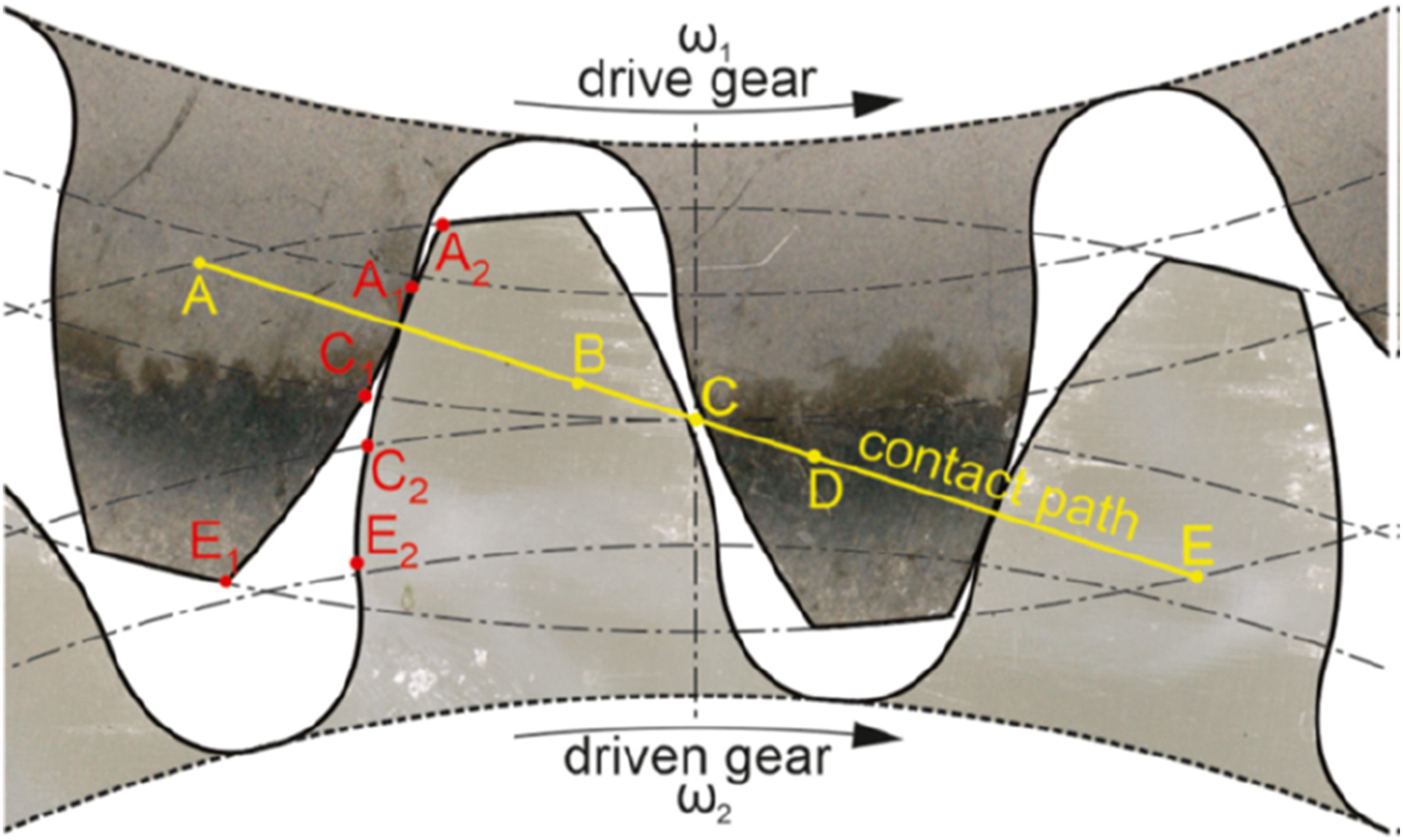
Although tribological behavior of materials can be assessed using pin-on-disc or disc-on-disc tests, these methods don’t fully replicate the complex motions seen in actual gear operation, such as combined rolling and sliding. Therefore, gear pair testing is preferred for accurately evaluating fatigue and wear, as it best simulates real application conditions. The theoretical contact path in involute gears is a straight line as shown in Figure 5 from point A to point E. Gear meshing begins at point A (A1 on the steel pinion and A2 on the E-glass fiber gear). Between A and B, two pairs of teeth share the load. From B to D, the load is carried by a single tooth pair. At point D, another pair comes into contact, redistributing the load until point E (E1 on the pinion, E2 on the gear). From A to C, the gear surfaces (A1C1 and A2C2) engage with a combined rolling and sliding motion, with the most sliding and thus the most wear occurring near the tooth root. At pitch point C, the sliding direction reverses. While ideally only rolling occurs at C, actual tooth deflection introduces some sliding as well, continuing through to point E.
33
Meshing geometry of the involute E-glass fiber polymer composite gear and steel pinion
33
.
L. Yan et al. introduced an online measurement technique utilizing line structured light to monitor rolling contact wear loss in real-time. This method allows for continuous tracking of wear on test specimens during operation, offering an effective way to evaluate the wear behavior of plastic gear materials under different working conditions. The system provides precise measurements of wear loss and enables detailed observation of surface morphology changes, making it a valuable tool for in-situ assessment of rolling contact fatigue in plastic gears. 94 Further investigation into wear resistance is essential due to its nonlinear behavior, which varies depending on the specific application. Although higher print resolution often leads to increased friction, it does not consistently result in greater wear under all circumstances. 28 Among gears made from ABS, PLA, and PETG materials, the most significant wear was observed at the root area, where the plastic gears begin to engage. In contrast, no wear occurred at the pitch point, as this region experiences only rolling contact. Wear progressively increases from the pitch circle to the point where the gears disengage. 9 A. Ignatijev et al. developed a computational model tested on a spur gear set, consisting of a POM (Polyoxymethylene) pinion paired with a case-hardened steel 16MnCr5 gear. The analysis revealed that the greatest wear on the gear flanks occurred at the tooth root and tip. 95
Thermal analysis
The thermal behavior of composite materials is largely influenced by the type of polymer incorporated into their structure. The polymer matrix plays a key role in determining essential thermal characteristics, including thermal conductivity, expansion, stability, and insulating ability. The inclusion of reinforcing elements like fibers or fillers can notably alter the thermal conductivity of the polymer, offering new possibilities for enhancing heat transfer efficiency within the composite material. 38 The operating temperature of polymer gears can be evaluated using either analytical or numerical approaches. Most of these methods describe the gear temperature increase as a combination of two main components: bulk temperature and flash temperature. The bulk temperature reflects the gradual, overall heating of the gear over time, while the flash temperature refers to a rapid, localized temperature spike near the heat generation site. Both types of temperature rise significantly impact the performance and durability of polymer gears. Elevated bulk temperatures can diminish the fatigue strength and may lead to material deformation, whereas high flash temperatures are often linked to surface scuffing on the gears. 96
Y. Zhang et al. conducted Differential Scanning Calorimetry (DSC) analyses at three distinct stages: prior to 3D printing, after printing the nylon filaments, and following a step load test on the nylon gear. The results indicated that the crystallinity of the material increased slightly after printing and was higher still in the gear tooth surface post-testing, compared to the raw filament. However, the glass transition and melting temperatures remained relatively consistent throughout all stages, demonstrating good thermal stability and repeatability during both the heating and cooling cycles after printing. 64 The bulk temperature of polymer gears plays a crucial role in determining their durability, as even a temperature increase of 10°C to 15°C can significantly impact the strength of polymer materials. To enhance performance, it’s essential to lower the ambient temperature and improve heat dissipation. This can be achieved by reducing the coefficient of friction (COF) or decreasing the transmitted power, either by lowering torque or operating speed. A larger gear size aids in heat dispersion, thereby helping to keep the gear temperature down—making the pinion especially important. In many cases, the combination of bulk and flash temperatures influences the mode of failure, highlighting the need for precise temperature modeling. 93 As temperature rises, the stiffness of the material decreases. This results in increased wear, particularly at the tooth root, and alters the wear distribution along the tooth flank. 95 Heat convection plays a vital role in cooling polymer spur gears operating under dry conditions, directly impacting their structural integrity. V. Roda-Casanova et al. developed a numerical model based on detailed Computational Fluid Dynamics (CFD) simulations to study heat convection on polymer spur gears. This model analyzes heat transfer through the gear’s external surfaces under real operating conditions. The results showed that as gear rotation speed increases, the relative velocity between the gear and the surrounding air also increases, thereby improving the gear’s cooling efficiency. 97
Service temperature and hygrothermal considerations for FDM polymer gears
Operating temperature strongly influences polymer gear material selection, as higher temperatures reduce stiffness, strength, and dimensional stability, while moisture exposure further degrades performance by lowering the effective glass transition temperature, particularly in hygroscopic polymers. 38
PLA and PETG, owing to their low glass transition temperatures, are generally limited to low-temperature gear applications because of early softening and wear. ABS and polycarbonate provide better thermal stability and maintain adequate strength at moderate temperatures, while nylon-based materials offer higher temperature capability but experience reduced stiffness under hot–wet conditions due to moisture absorption. 64
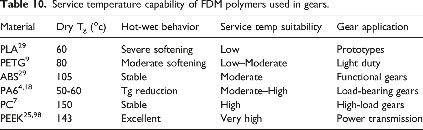
Service temperature capability of FDM polymers used in gears.
Lubrication
In lubricated gears, less heat tends to accumulate on the tooth flanks due to a lower coefficient of friction and the lubricant’s ability to dissipate and carry away heat from the contact area. As a result, polymer gears operating with lubrication typically experience lower temperatures, which can enhance the fatigue life of the tooth root compared to gears running dry. S. Markovic and M. Kalin investigated the fatigue life of polymer/steel gear pairs under both dry and oil-lubricated conditions, testing at three torque levels (0.8, 1.0, and 1.2 Nm) and two root temperatures (25°C and 80°C). Their findings showed that lubrication reduces maximum stress at the tooth root by up to 13%, which can have a nonlinear effect on durability extending fatigue life by 2 to 5.2 times compared to dry-running gears under equivalent conditions. 99
Finite Element Analysis (FEA)
The finite element method (FEM) is commonly used as a direct and effective approach for analyzing the mechanical behavior of structures. 100 An eight-node brick element (C3D8) was utilized, with mesh refinement applied at the gear tooth root to achieve accurate stress field distribution. 101 M.A. Ghaffari et al. conducted three-dimensional finite element analyses to examine both fatigue crack initiation and propagation in gear teeth. A linear elastic fracture mechanics approach was employed to model mixed-mode fatigue crack growth after crack initiation. They also evaluated the use of composite patches to extend the fatigue life of gear teeth and found that Boron/Epoxy patches significantly improved fatigue crack propagation resistance. 102 H. He et al. developed an advanced gear bending fatigue model that incorporates residual stress and hardness gradients, using continuum damage theory to predict the bending fatigue life of case-hardened wind turbine gears. Their study analyzed the progression of material damage, stress responses, and mechanical property changes, along with the influence of residual stress and surface hardness on fatigue life. The results showed that gear bending fatigue follows a nonlinear pattern of damage evolution and damage rate. Ultimately, fatigue failure was attributed to the accumulation of damage and the degradation of the material’s mechanical properties. 103 H. He et al. proposed a damage-coupled elastic-plastic numerical model to investigate contact fatigue crack initiation in heavy-duty wind turbine gears. The model simultaneously accounted for both elastic and plastic damage evolution. Their findings indicated that as the normal load increases, the contribution of plastic deformation to overall damage becomes more significant. 104
K. Vuckovic et al. developed a quasi-static finite element model (FEM) of a spur gear pair and compared the results with existing standards. Their study focused on evaluating the influence of adjacent teeth on the bending fatigue life of spur gears. It was found that the presence of adjacent teeth affects both the mean bending stress and the bending stress amplitude, which are critical factors in gear fatigue performance. 105 Z. Sun et al. introduced a detailed deterministic model designed to evaluate the meshing behavior of gears with rough surfaces, with the goal of improving their operational efficiency. The model integrated gear surface modeling, reconstruction, contact analysis, and meshing performance assessment. It was specifically tailored to account for variations in surface height distribution and material hardness, establishing a multi-scale analysis approach that links micro-topographical features to the overall performance of the gear system. 106 H. He et al. developed a damage-coupled gear bending fatigue model to assess the fatigue performance of gears while accounting for residual stress (RS) and hardness. They further derived unified gear bending stress-life (S-N) equations based on the Basquin equation to quantitatively analyze the impact of residual stress and hardness on gear bending fatigue life. 107
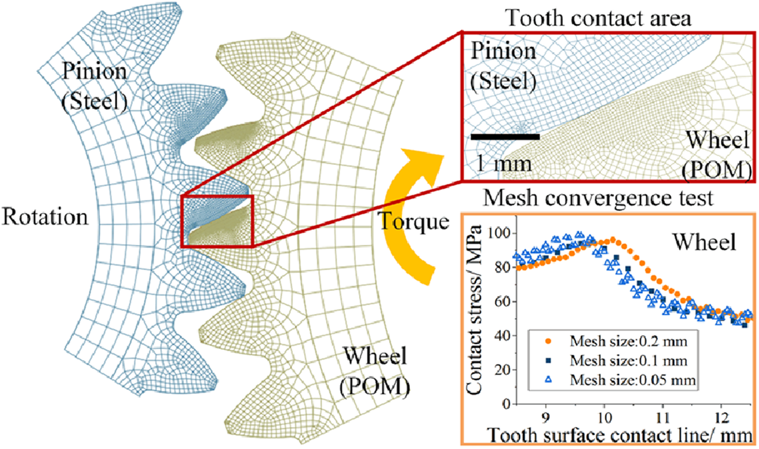
The Figure 6 presents a finite element based gear meshing analysis of a steel pinion and a POM wheel, highlighting tooth contact behavior and mesh convergence. The FEA model captures the localized tooth contact zone and the resulting contact stress distribution along the tooth surface under applied torque. The mesh convergence study demonstrates that finer element sizes lead to stable and mesh-independent contact stress predictions, confirming the reliability of the numerical model for evaluating contact mechanics in metal–polymer gear pairs.
51
The torque-carrying capacity of a polymer gear is primarily governed by the stress concentration at the tooth-root fillet, where bending stresses reach their maximum values. In FDM-manufactured gears, this limitation is further influenced by material anisotropy arising from filament deposition. Since mechanical strength is highest along the filament direction and weakest across interlayer interfaces, filament orientation plays a critical role in determining gear performance.
108
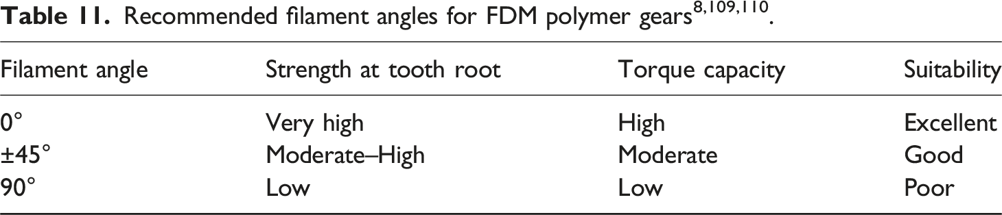
Optimal strength and fatigue resistance are achieved when filaments are oriented circumferentially or tangentially, aligning with the principal tensile stresses at the tooth root. Finite element analysis (FEA) can be employed to identify these stress trajectories and to evaluate different raster orientations using orthotropic material models, thereby enabling improved torque capacity and reduced risk of tooth-root cracking or delamination. The Table 11 illustrates how filament orientation influences the performance of FDM-printed gears. Filaments aligned at 0° deliver the highest strength and torque resistance, ±45° orientations provide balanced behavior under moderate loads, and 90° alignment leads to low load-carrying capability. The simulation model of gear mesh analysis
85
.
Methodologies for predicting gear failure
There is ongoing and intensive development of new algorithms, particularly those leveraging artificial neural networks and other machine learning techniques, as they allow for the incorporation of a greater number of input variables.
111
Since gear contact fatigue testing is both time-consuming and expensive, obtaining large volumes of accurate test data poses significant challenges. As a result, developing reliable models for predicting gear contact fatigue life using small sample sets is essential. A promising approach is to combine physics-based models with data-driven methods, harnessing the strengths of both to enhance prediction accuracy and efficiency.
84
W. Dong et al. employed a predictive model to estimate the contact fatigue life of sun and planetary gears within a drivetrain system. A simplified pitting prediction model was applied to evaluate the service life of these components. The analysis revealed that the sun gear is more susceptible to pitting compared to the planet gears. For both gear types, the most critical regions prone to pitting were identified in their respective recess areas.
112
X. Li et al. studied gear contact fatigue failure by developing a numerical model that incorporates surface integrity to predict gear fatigue life. This modeling approach enables the rapid identification of relationships between surface integrity characteristics and contact fatigue performance. It also offers valuable insights into the rolling contact fatigue process, making it a useful tool for designing surface integrity parameters and optimizing manufacturing techniques such as grinding and shot peening. Their findings indicated that interference between the tooth tip and root, along with improper residual stress distribution, were the main contributors to gear failure.
113
Y. Yan developed a fatigue reliability model for gear transmission systems based on a weighted average algorithm. In this approach, the random loading process was characterized using a set of representative load histories. The torque history was then converted into a corresponding maximum contact stress history on the gear tooth surface, which served as the input for subsequent cumulative fatigue damage calculations and reliability assessments.
114
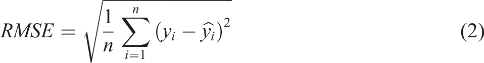
To evaluate the accuracy of the fatigue life prediction model, the mean absolute percentage error (MAPE) and root mean squared error (RMSE) metrics were employed, defined as in equations (1) and (2).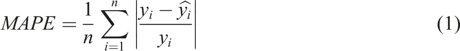
K. Feng et al. utilized the Relevance Vector Machine (RVM) model to predict the remaining useful life (RUL) of gear transmission systems, incorporating a proposed health monitoring indicator. Accurate RUL prediction plays a vital role in enhancing predictive maintenance strategies and the overall health management of gear transmission systems. 115 Y. Li et al. trained a neural network model using low-cost, widely available rolling contact fatigue data to predict fatigue life while accounting for surface integrity and contact stress. The knowledge of how surface integrity and contact stress influence fatigue life, learned from this data, was then transferred to gear applications. As a result, a gear contact fatigue life prediction model capable of covering a broad range of surface integrity conditions and contact stresses can be developed using only a limited number of gear fatigue samples. 116 Y. Zhang et al. introduced an innovative probabilistic fatigue analysis model to evaluate the effect of notch size on fatigue life, utilizing the Theory of Critical Distances (TCD). The model incorporates the Weibull distribution within the TCD framework for probabilistic assessment, while the influence of size effects on the critical distance is represented using the Highly Stressed Volume (HSV) method and the Stress Concentration Factor (SCF). 88 Additionally, advanced techniques such as Artificial Neural Networks (ANN) are employed to predict the remaining useful life of mechanical components, thereby facilitating more effective proactive maintenance planning. 117
Conclusion
This review consolidates the current state of research on polymer gears manufactured using Fused Deposition Modeling (FDM), with particular emphasis on materials, process parameters, and performance outcomes. Conventional thermoplastics such as PLA, ABS, PETG, Nylon, and POM provide varying balances of printability, dimensional accuracy, and strength, while high-performance polymers like PEEK extend the applicability of FDM gears to high-temperature and high-load conditions, although it has significant processing challenges. Reinforcements play a crucial role in enhancing gear performance: extensive work on carbon fiber and glass fiber composites has demonstrated marked improvements in wear resistance, fatigue life, and thermal stability. However, aramid fiber-reinforced composites remain comparatively underexplored, despite their promising mechanical and thermal properties, and should receive greater research attention in the future.
Comparisons with traditional methods such as injection molding and machining reveal that while these techniques deliver higher dimensional accuracy and load-bearing capacity, FDM stands out for its design flexibility, rapid prototyping, and ability to incorporate advanced reinforcements and hybrid material strategies. Post-processing treatments, polymer blending, and bio-based composites further extend the performance landscape, yet challenges such as moisture absorption, warpage, and print anisotropy continue to limit widespread industrial adoption. FDM offers a promising route for fabricating polymer gears with complex geometries, reduced weight, and cost-effective prototyping. Studies show that optimized FDM settings can enhance fatigue resistance, dimensional accuracy, and wear behavior, making FDM a viable method for producing gears for medium-load applications. This review highlights that material selection, printing parameters, and reinforcement strategies significantly influence the mechanical and thermal performance of 3D-printed gears. Many published works rely on material-level testing to infer gear performance; however, direct comparisons reveal that such results do not always translate to actual gear operation due to the influence of tooth geometry, meshing conditions, and anisotropic strength. This limitation underscores the need for integrated gear-level testing to enable meaningful comparison across studies.
In conclusion, FDM has emerged as a viable technology for producing functional polymer gears, especially for light-to medium-duty applications. To bridge the performance gap with metallic gears and injection-molded polymers, future research should focus on optimizing high-performance composites, advancing aramid fiber reinforcement, exploring sustainable bio-based materials, and establishing standardized testing protocols under real-world operating conditions. Addressing these challenges will enable the development of lightweight, durable, and cost-effective polymer gears tailored for next-generation power transmission systems. Importantly, such advancements hold significant industrial relevance, particularly for automotive, aerospace, robotics, and consumer electronics, where reducing weight, minimizing noise, and enhancing energy efficiency are critical to achieving sustainable and high-performance mechanical systems. Future investigations should aim to enhance the performance and operational reliability of additively manufactured polymer gears by advancing material development, process optimization, and gear design methodologies. The use of fiber-reinforced and hybrid polymer composites with improved interlayer adhesion offers significant potential for increasing fatigue life and wear resistance. Moreover, systematic studies examining the combined influence of build orientation, raster configuration, and infill architecture under realistic service conditions are necessary to better understand long-term durability. The integration of numerical simulations with experimental validation, particularly those incorporating viscoelastic and fatigue-based material models, would enable improved prediction of gear deformation and failure behavior. In addition, the application of post-processing techniques would enhance surface finish and dimensional accuracy represents a promising approach for extending the service life of FDM-fabricated polymer gears.
Footnotes
Declaration of conflicting interests
The authors declared no potential conflicts of interest with respect to the research, authorship, and/or publication of this article.
Funding
The authors received no financial support for the research, authorship, and/or publication of this article.